


WELL72
Table of contents
 Loading...
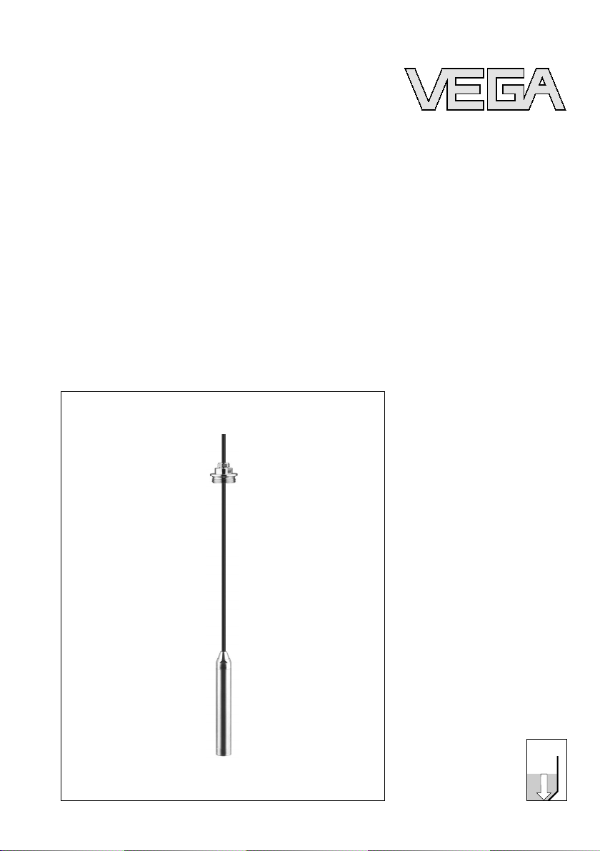
Operating Instruction
p
VEGAWELL 72
4 … 20 mA
s
Process pressure/
Hydrostat
ic

Content
Content
1 About this document
1.1 Function . . . . . . . . . . . . . . . . . . . . . . . . . . . . .
1.2 Target group . . . . . . . . . . . . . . . . . . . . . . . . . .
1.3 Symbolism used . . . . . . . . . . . . . . . . . . . . . . .
2 For your safety
2.1 Authorised personnel. . . . . . . . . . . . . . . . . . . .
2.2 Appropriate use. . . . . . . . . . . . . . . . . . . . . . . .
2.3 Warning about misuse . . . . . . . . . . . . . . . . . . .
2.4 General safety instructions . . . . . . . . . . . . . . . .
2.5 Safety approval markings and safety tips . . . . .
2.6 CE conformity . . . . . . . . . . . . . . . . . . . . . . . . .
2.7 Fulfilling of NAMUR recommendations . . . . . . .
2.8 Safety instructions for Ex areas . . . . . . . . . . . .
2.9 Environmental instructions . . . . . . . . . . . . . . . .
3 Product description
3.1 Configuration. . . . . . . . . . . . . . . . . . . . . . . . . .
3.2 Principle of operation . . . . . . . . . . . . . . . . . . . .
3.3 Operation . . . . . . . . . . . . . . . . . . . . . . . . . . . .
3.4 Packaging, transport and storage . . . . . . . . . . .
4 Mounting
4.1 General instructions. . . . . . . . . . . . . . . . . . . . .
4.2 Mounting steps with straining clamp . . . . . . . . .
4.3 Mounting steps with screwed connection . . . . .
4.4 Mounting steps with socket and plastic housing.
4
4
4
5
5
5
5
6
6
6
6
6
8
10
10
10
12
13
14
15
5 Connecting to power supply
5.1 Preparing the connection . . . . . . . . . . . . . . . . .
5.2 Connection procedure . . . . . . . . . . . . . . . . . . .
5.3 Wiring plan . . . . . . . . . . . . . . . . . . . . . . . . . . .
17
19
20
6 Set up
6.1 Setup procedure . . . . . . . . . . . . . . . . . . . . . . .
22
7 Maintenance and fault rectification
7.1 Maintenance . . . . . . . . . . . . . . . . . . . . . . . . . .
7.2 Remove interferences . . . . . . . . . . . . . . . . . . .
7.3 Shorten suspension cable . . . . . . . . . . . . . . . .
7.4 Instrument repair . . . . . . . . . . . . . . . . . . . . . . .
23
23
24
26
8 Dismounting
8.1 Dismounting steps. . . . . . . . . . . . . . . . . . . . . .
2 VEGAWELL 72 • 4 … 20 mA
28
27501-EN-080806
Content
8.2 Disposal . . .
. . . . . . . . . . . . . . . . . . . . . . . . . .
9 Supplement
9.1 Technical data. . . . . . . . . . . . . . . . . . . . . . . . .
9.2 Dimensions. . . . . . . . . . . . . . . . . . . . . . . . . . .
9.3 Industrial property rights. . . . . . . . . . . . . . . . . .
9.4 Trademark . . . . . . . . . . . . . . . . . . . . . . . . . . .
28
29
36
37
37
Supplementary documentation
Information:
Supplementary document
s appropriate to the ordered version
come with the delivery. You can find them listed in chapter
"Product description".
Instructions manuals for accessories and replacement
parts
Tip:
To ensure reliable
setup and operation of your VEGAWELL 72,
we offer accessories and replacement parts. The associated
documents are:
l 32798 - VEGABOX 02
27501-EN-080806
VEGAWELL 72 • 4 … 20 mA 3
1 About this document
1 About this document
1.1 Function
This operating instructions manual provides all the information
you need for mounting, connection and setup as well as
important instructions for maintenance and fault rectification.
Please read this information before putting the instrument into
operation and keep this manual accessible in the immediate
vicinity of the device.
1.2 Target group
This operating instructions manual is directed to trained
personnel. The contents of this manual should be made
available to these personnel and put into practice by them.
1.3 Symbolism used
Information, tip, note
This symbol
indicates helpful additional information.
Caution: If this warning
tions can result.
Warning: If this warning is ignored, injury to persons and/or
serious damage to the instrument can result.
Danger: If this warning is ignored, serious injury to persons
and/or destruction of the instrument can result.
Ex applications
This symbol
l List
The dot set in front indicates a list with no implied sequence.
indicates special instructions for Ex applications.
is ignored, faults or malfunc-
à Action
This arrow indicates a
1 Sequence
Numbers set in front indicate successive steps in a procedure.
4 VEGAWELL 72 • 4 … 20 mA
single action.
27501-EN-080806

2 For your safety
2 For your safety
2.1 Authorised
All operations descr
must be carried out only by trained specialist personnel
authorised by the plant operator.
During work on and with the device the required personal
protection equipment must always be worn.
personnel
ibed in this operating instructions manual
2.2 Appropriate use
VEGAWELL 72 is a suspension pressure transmitter for level
and gauge measurement.
You can find detailed information on the application range in
chapter "Product description".
Operational reliability is ensured only if the instrument is
properly used according to the specifications in the operating
instructions manual as well as possible supplementary
instructions.
For safety and warranty reasons, any invasive work on the
device beyond that described in the operating instructions
manual may be carried out only by personnel authorised by the
manufacturer. Arbitrary conversions or modifications are
explicitly forbidden.
2.3 Warning about misuse
Inappropriate or incorrect use of the instrument can give rise to
application-specific hazards, e.g. vessel overfill or damage to
system components through incorrect mounting or adjustment.
2.4 General safety instructions
This is a high-tech instrument requiring the strict observance of
standard regulations and guidelines. The user must take note
of the safety instructions in this operating instructions manual,
the country-specific installation standards as well as all
prevailing safety regulations and accident prevention rules.
The instrument must only be operated in a technically flawless
and reliable condition. The operator is responsible for troublefree operation of the instrument.
27501-EN-080806
VEGAWELL 72 • 4 … 20 mA 5

2 For your safety
During the entire duration of use, the user
must make sure that
the occupational safety measures taken always comply with
current valid policy as well as new regulations.
2.5 Safety approval markings and safety tips
The safety approval markings and safety tips on the device
must be observed.
2.6 CE conformity
The protection goals of the EMC Directive 2004/108/EC (EMC)
and the Low Voltage Directive 2006/95/EC (LVD) are fulfilled.
Conformity has been judged according to the following
standards:
EMC: EN 61326: 2004
(electrical instruments for control technology and laboratory
use - EMC requirements)
l Emission: Class A
l Susceptibil
ity: Industrial
areas
LVD: EN 61010-1: 2001
(safety
regulatio
ns for electrical measurement, control and
laboratory instruments - part 1: General requirements)
2.7 Fulfilling of NAMUR recommendations
With respect to interference resistance and emitted interference, the NAMUR recommendation NE 21 is fulfilled.
2.8 Safety instructions for Ex areas
Please note the Ex-specific safety information for installation
and operation in Ex areas. These safety instructions are part of
the operating instructions manual and come with the Exapproved instruments.
2.9 Environmental instructions
Protection of the environment is one of our most important
duties. That is why we have introduced an environment
management system with the goal of continuously improving
company environmental protection. The environment management system is certified according to DIN EN ISO 14001.
6 VEGAWELL 72 • 4 … 20 mA
27501-EN-080806

2 For your safety
Please help us fulfil this obligation
by observing the environ-
mental instructions in this manual:
l Chapter "Packaging, transport and storage"
l Chapter "Disposal"
27501-EN-080806
VEGAWELL 72 • 4 … 20 mA 7

3 Product description
3 Product description
3.1 Configuration
Scope of delivery
Components
The scope of delivery encompasses:
l VEGAWELL 72 pressure transmitter with
l optionally available with straining clamp, screwed con-
suspension cable
nection or plastic housing with cable locking
l or VEGAWELL 72 pressure transmitter with connection
tube
l Documentation
- this operating
instructions manual
- test certificate
- Ex-specific "Safety instructions" (with Ex-versions)
- if necessary, further certificates
VEGAWELL 72 with suspension cable consists of the following
components:
l Transmitter
l suspension cable (optionall
y available
with plastic housing)
VEGAWELL 72 with connection tube consists of the following
components:
l Transmitter
l Connection tube
l Housing or direct cable outlet, each with threaded
connection
The
components are available in different versions.
8 VEGAWELL 72 • 4 … 20 mA
27501-EN-080806
3
2
1
4
3 Product description
screwed connection
Type label
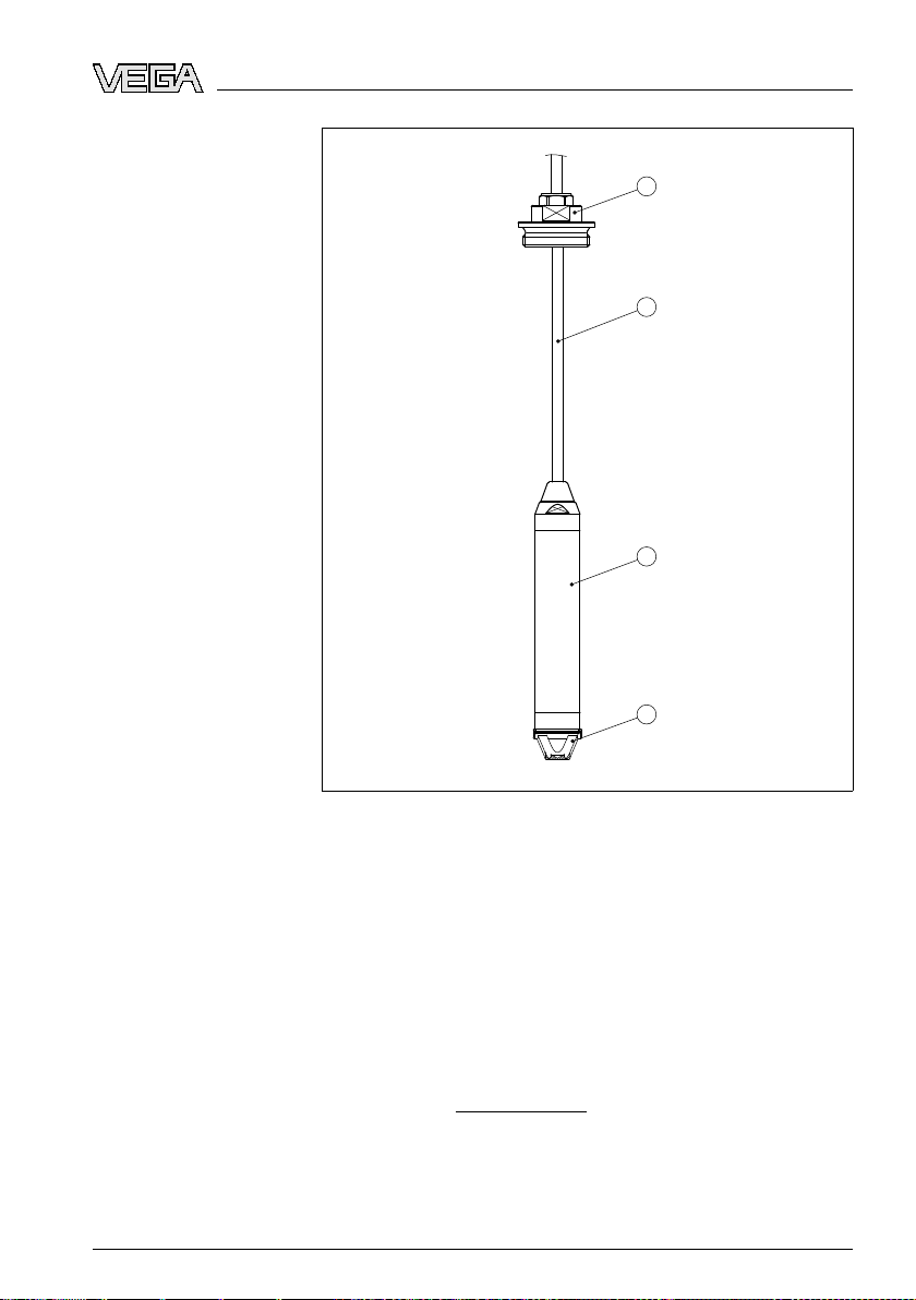
Fig. 1: Example of a VEGAWELL 72 with
1 Transmitter
2 Suspension cable
3 Threaded fitting
4 Protective cap
The type label contains the most important data for identi-
fication and use of the instrument:
l Article
l Serial number
l Technical data
l Article numbers documentation
With the serial
instrument via "
number
number
number, you can access the delivery data of the
www.vega.com", "VEGA Tools" and "serial
search". In addition to the type label outside, you can
also find the serial number on the inside of the instrument.
27501-EN-080806
VEGAWELL 72 • 4 … 20 mA 9

3 Product description
Application range
Functional principle
Voltage supply
3.2 Principle of
operation
VEGAWELL 72 is used for level and gauge measurement in
wells, basins and atmospherically open vessels particularly in
the water/waste water industry as well as in the shipbuilding
industry.
The
1)
actual sensor element is the CERTEC
®
measuring cell
with rugged ceramic diaphragm. The hydrostatic pressure
causes a capacitance change in the measuring cell via the
ceramic diaphragm. This change is converted into an
appropriate output signal.
Two-wire electronics 4 … 20 mA for power supply and
measured value transmission on the same cable.
The supply voltage range can differ depending on the
instrument version.
Data for power supply are specified in chapter "Technical
data".
3.3 Operation
VEGAWELL 72 with 4 … 20 mA electronics has no adjustment
option.
3.4 Packaging, transport and storage
Packaging
Your instrument was protected by packaging during transport.
Its capacity to handle normal loads during transport is assured
by a test according to DIN EN 24180.
The packaging of standard instruments consists of environ-
ment-friendly, recyclable cardboard. For special versions, PE
foam or PE foil is also used. Dispose of the packaging material
via specialised recycling companies.
Transport
Transport must be carried out under consideration of the notes
on the transport packaging. Nonobservance of these instructions can cause damage to the device.
Transport inspection
The delivery must be checked for completeness and possible
transit damage immediately at receipt. Ascertained transit
damage or concealed defects must be appropriately dealt
with.
1)
For use in closed vessels under vacuum, VEGAWELL 72 is available with
absolute pressure measuring ranges.
10 VEGAWELL 72 • 4 … 20 mA
27501-EN-080806

3 Product description
Storage
Storage
temperature
and transport
Up to the time of installation, the packages must be left closed
and stored according to the orientation and storage markings
on the outside.
Unless otherwise indicated, the packages must be stored only
under the following conditions:
l Not
l Dry and dust free
l Not exposed to corrosive media
l Protected against solar
l Avoiding mechanical shock and vibration
l Storage and transport temperature see "Supplement -
l Relative humidity 20 … 85 %
in the open
radiation
Technical data - Ambient condi
tions"
27501-EN-080806
VEGAWELL 72 • 4 … 20 mA 11
4 Mounting
4 Mounting
Mounting position
Pressure compensation
4.1 General ins
Note the following
tructions
points when selecting the installation
location.
l Sidewa
ys movements of the transmitter can cause
measurement errors
à Therefore, mount VEGAWELL 72 in
a calm area or in a
suitable protective tube
Information:
We recommend
the measuring instrument holder from the
VEGA line of accessories (article no. BARMONT.B) for
fastening VEGAWELL 72.
l The protective cover prevents mechanical damage to the
measuring cell. It
should only be removed when the sensor
is deployed in extremely polluted water.
l The
connection cable has a capillary for atmospheric
pressure compensation
à Therefore lead
the cable end into a dry space or directly
into a suitable terminal housing.
Information:
this
For
contains
purpose, VEGA recommends VEGABOX 02. It
terminals and a filter element for pressure compensation. A suitable protective cover is available for outdoor
mounting.
Mounting example
12 VEGAWELL 72 • 4 … 20 mA
27501-EN-080806
Loading...