


XT302C Deluxe Programmable
Heat-Cool Thermostat
18-HD25D7-5
INSTALLER'S GUIDE
APPLICATION
The XT302C Deluxe Programmable Heat-Cool Thermostat provides electrnic control of 24 Vac single-zone multistage systems. Refer to Table 1 for a general description of the thermostat. This thermostat requires a common wire to supply power.
Table 1. Description of XT302C.
Model |
System |
Changeover |
System Selection |
Fan Selection |
Comments |
|
|
|
|
|
|
|
|
XT302C |
Multistage |
Automatic |
Heat-Off-Cool-Auto |
On-Auto |
System and fan selections are done by |
|
|
|
|
|
|
keyboard. |
|
|
|
|
|
|
|
|
RECYCLING NOTICE
If this thermostat is replacing a thermostat that contains mercury in a sealed tube, do not place your old thermostat in the trash.
Contact your local waste management authority for instructions regarding recycling and the proper disposal of the old thermostat.
Wallplate Installation
Position wallplate horizontally on the wall or on a 2 in. x 4 in. wiring box.
1.Position and level the wallplate for appearance only (the thermostat will function properly even when
not level).
INSTALLATION
When Installing this Thermostat...
1.Read these instructions carefully. Failure to follow the instructions can damage the product or cause a hazardous condition.
2.Check the ratings given in the instructions and on the product to make sure the product is suitable for your application.
3.Installer must be a trained, experienced service technician.
4.After completing installation, use these instructions to check out the product operation.
Location
Install the thermostat about 5 ft (1.5m) above the floor in an area with good air circulation at average temperature. See Fig. 1. Avoid installing the thermostat where it can be affected by the following:
•Drafts, or dead spots behind doors and in corners.
•Hot or cold air from ducts.
•Radiant heat from sun or appliances.
•Concealed pipes and chimneys.
•Unheated (uncooled) areas such as an outside wall behind the thermostat.
YES
NO
NO
5 FEET
[1.5 METERS]
M17106
Fig. 1. Typical location of thermostat.
® U.S. Registered Trademark |
|
Copyright © American Standard Inc. 1999 |
69-1213-1 |

XT302C DELUXE PROGRAMMABLE HEAT-COOL THERMOSTAT
WALL
WIRES
THROUGH WALL
WALL ANCHORS
(2)
MOUNTING
HOLES
 MOUNTING
SCREWS
M15044
Fig. 2. Mounting the wallplate.
2.Use a pencil to mark the mounting holes. See Fig. 2.
3.Remove the wallplate from the wall and drill two 3/16 inch holes in the wall (if drywall) as marked. For firmer material such as plaster, drill two 7/32 inch holes. Gently tap anchors (provided) into the drilled holes until flush with the wall.
4.Position the wallplate over the holes, pulling wires through the wiring opening.
5.Loosely insert the mounting screws into the holes.
6.Tighten mounting screws.
THERMOSTAT
B |
Y1 |
Y2 |
W1 W2 G |
R |
H |
H |
OT |
OT |
BLUE |
YELLOW |
BROWN |
|
WHITE |
BLACK |
|
GREEN |
RED |
|
|
|
COMPRESSOR |
|
HEAT |
|
|
|
||
|
|
CONTACTOR 2 |
|
STAGE 2 |
|
|
|||
COMPRESSOR |
HEAT |
FAN |
|
CONTACTOR 1 |
STAGE 1 |
||
|
|
|
|
|
|
|
|
|
|
|
|
HUMIDISTAT |
|
OUTDOOR |
|
|||||
|
|
TEMPERATURE |
|||||||
|
OPENS ON RISE |
|
|||||||
|
|
SENSOR |
|
||||||
|
TAYSTAT253A |
|
|
||||||
|
|
TAYSENS100A |
|||||||
|
|
|
|
|
|
|
|
L1 |
|
|
|
|
|
|
|
|
|
|
|
|
|
|
|
|
|
|
|
|
|
|
|
|
|
|
|
|
|
(HOT) |
1 |
|
|
|
|
|
|
|
|
L2 |
|
|
|
|
|
|
|
|
|
|
|
|
|
|
|
|
|
|
|
|
|
1 POWER SUPPLY. PROVIDE DISCONNECT MEANS |
TRANSFORMER |
|
|
AND OVERLOAD PROTECTION AS REQUIRED. |
M17116 |
Fig. 3. Typical hookup of XT302C in a heat cool system.
|
FOR STRAIGHT |
|
FOR WRAPAROUND |
INSERTION STRIP |
|
5/16 IN. (8 MM). |
||
INSERTION STRIP |
||
|
||
7/16 IN. (11 MM). |
M4826 |
|
|
Fig. 4. Proper wiring technique.
Mounting Thermostat
1.Engage tabs at the top of the thermostat and wallplate. See Fig. 5.
2.Press lower edge of case to close and latch.
NOTE: To remove thermostat from wall, first pull out at bottom of thermostat; remove top last.
WIRING
All wiring must comply with local electrical codes and ordinances. Refer to Fig. 3 for typical hookup diagram. A letter code is located near each terminal for identification.
 WARNING
Electronic Shock or Equipment Damage Hazard. Can shock individuals or cause equipment damage.
Disconnect power before wiring to prevent electrical shock or equipment damage.
1.Loosen the terminal screws on the wallplate and connect the system wires. See Fig. 4.
NOTE: Use 18 gauge, color-coded thermostat cable for proper wiring.
2.Securely tighten each terminal screw.
3.Push excess wire back into the hole.
4.Plug the hole with nonflammable insulation to prevent drafts from affecting the thermostat.
Pub. No. 18-HD25D7-5
A. ENGAGE TABS
AT TOP OF
THERMOSTAT
AND WALLPLATE.
B.PRESS LOWER EDGE OF CASE
TO LATCH. |
M17151 |
Fig. 5. Mounting thermostat on wallplate.
69-1213—1 (T8624) |
2 |
XT302C DELUXE PROGRAMMABLE HEAT-COOL THERMOSTAT
SET WAKE TIMES
AND SETPOINTS
INCREASE TIME
SETTING OR SCROLL
FORWARD THROUGH
INSTALLER SETUP
AND SYSTEM TEST
SET CURRENT
DAY AND TIME
RETURN TO NORMAL
OPERATIONS
SET CURRENT OR
PROGRAM DAY
ENTER INDEFINITE
OR TIMED HOLD MODE 
DECREASE TIME SETTING OR SCROLL BACKWARD THROUGH INSTALLER SETUP AND SYSTEM TEST
CHANGE BETWEEN
DAYLIGHT SAVINGS
AND STANDARD TIME
Run |
Set Current |
Program |
Day/Time |
Hold Temp |
Day |
|
Daylight |
|
Time |
COPY ONE PROGRAMMED DAY TO ANOTHER DAY
INCREASE TEMPERATURE SETTING OR SCROLL |
DECREASE |
|||||
FORWARD THROUGH INSTALLER SETUP OPTIONS |
TEMPERATURE |
|||||
|
|
|
|
|
SETTING OR |
|
|
|
|
|
|
SCROLL BACKWARD |
|
|
|
|
|
|
THROUGH INSTALLER |
|
|
|
|
|
|
SETUP OPTIONS |
|
|
|
|
|
|
DISPLAY |
|
|
|
|
|
|
INFORMATION |
|
|
|
|
|
|
SUCH AS PRESENT |
|
|
|
|
|
|
SETTINGS |
|
|
|
|
|
|
AND OUTDOOR |
|
|
|
|
|
|
TEMPERATURE |
|
|
|
|
|
|
SET RETURN TIMES |
|
Wake |
Leave |
|
|
|
AND SETPOINTS |
|
Return |
Sleep |
|||||
SET SLEEP TIMES |
||||||
Time |
Set Program |
|
|
AND SETPOINTS |
||
|
|
|
||||
Heat/Cool |
Filter |
System |
Fan |
SET LEAVE TIMES |
||
Settings |
||||||
|
|
|
|
|
AND SETPOINTS |
|
Copy |
|
|
|
|
SELECT FAN |
|
|
|
|
|
|
||
|
|
|
|
|
OPERATION |
|
CHANGE BETWEEN |
SELECT FILTER |
SELECT SYSTEM |
||||
HEATING AND |
EXPIRATION IN |
OPERATION (HEAT, |
||||
COOLING SETPOINTS |
NUMBER OF DAYS |
COOL, OFF, AUTO) |
||||
M17118
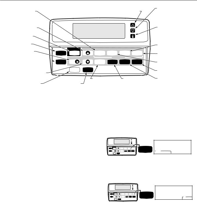
Fig. 6. XT302C key locations and descriptions.
Using Thermostat Keys
The thermostat keys are used to:
•Set current day and time,
•Program times and setpoints for heating and cooling,
•Temporarily override program temperatures,
•Display present setting,
•Configure Installer Setup,
•Check Self-Test,
•Display outdoor temperature (optional accessory),
•Set the system operation, and
•Set the fan operation.
See Fig. 6 for keypad explanation.
SETTINGS
System and Fan Settings
The system default setting is Heat and the fan default setting is Auto. Use the System and Fan keys to change the settings. See Figs. 7 and 8. The fan settings can be set for each program period individually. The system selection is for all the program periods.
System settings control the thermostat operation as follows:
Heat: The thermostat controls the heating. Off: Both the heating and cooling are off. Cool: The thermostat controls the cooling.
Auto: The thermostat automatically changes between heating and cooling operation, depending on the indoor temperature.
Run |
Set Current |
|
Wake |
Leave |
Return |
Sleep |
System |
Program |
Day/Time |
|
|||||
|
|
Time |
|
Set Program |
|
||
Hold Temp |
Day |
|
Settings |
Filter |
System |
Fan |
System |
|
|
|
Heat/Cool |
|
|
|
|
|
Daylight |
Copy |
|
|
|
|
Heat Off Cool Auto |
|
Time |
|
|
|
|
|
|
M12956
Fig.7. System key location and display.
Fan settings control the system fan as follows:
On: Fan operates continuously.
Auto: Fan operates with equipment.
Run |
Set Current |
|
Wake |
Leave |
Return |
Sleep |
Fan |
Program |
Day/Time |
|
|||||
|
|
Time |
|
Set Program |
|
||
Hold Temp |
Day |
|
Heat/Cool |
Filter |
System |
Fan |
Fan |
|
|
|
Settings |
|
|
|
|
|
Daylight |
Copy |
|
|
|
|
OnAuto |
|
Time |
|
|
|
|
|
|
M12957
Fig. 8. Fan key location and display.
NOTE: Always press the keys with your fingertip or similar blunt tool. Sharp instruments like a pen or pencil point can damage the keyboard.
Pub. No. 18-HD25D7-5
3 |
69-1213—1 (T8624) |
XT302C DELUXE PROGRAMMABLE HEAT-COOL THERMOSTAT
Temperature Settings
Refer to Table 2 for the default program. For 7-Day and 24-Hour Operation, the settings are the same for each day of the week. Refer to the Owners Guide, Pub. No. 22-5127-04, for instructions on changing the default settings.
Table 2. Default Program Settings.
|
|
Heat |
Cool |
Fan |
Period |
Time |
Setpoint |
Setpoint |
Setting |
Wake |
6:00 AM |
70°F |
78°F |
Auto |
|
|
(21°C) |
(25.5°C) |
|
Leave |
8:00 AM |
62°F |
85°F |
Auto |
|
|
(16.5°C) |
(29.5°C) |
|
Return |
5:00 PM |
70°F |
78°F |
Auto |
|
|
(21°C) |
(25.5°C) |
|
Sleep |
10:00 PM |
62°F |
82°F |
Auto |
|
|
(16.5°C) |
(28°C) |
|
The Leave, Return and Sleep periods may be cleared. For example, the daytime energy-savings period (from Leave to Return) may not be used by the homeowner. To clear any period, follow the instructions in the Owners Guide in the
Clearing Schedule Period section.
Comfort-R™ |
|
OFF |
CONTROL |
|
|
Adaptive |
|
ON |
|
||
Intelligent |
|
|
Recovery™ |
|
|
CONTROL |
|
|
(A HONEYWELL |
|
|
TRADEMARK) |
|
|
COOLING |
|
ON |
|
||
DROOP |
|
|
TEMPERATURE |
|
FARENHEIT (°F) |
|
||
DISPLAY |
|
|
CLOCK |
|
24-HOUR |
|
||
FORMAT |
|
CLOCK FORMAT |
SYSTEM |
|
AUTO/MANUAL |
|
||
SETTING |
|
(SYSTEM |
(HEATING |
|
AUTOMATICALLY |
AND |
|
SELECTS |
COOLING |
|
HEAT OR COOL; |
SETTING) |
|
YOU CAN |
|
|
SELECT HEAT, |
|
|
COOL OR OFF.) |

 ON
ON

 OFF (CONVENTIONAL RECOVERY)

 OFF
OFF
CENTIGRADE (°C)
24-HOUR CLOCK FORMAT

 MANUAL ONLY (YOU SELECT HEAT, COOL OR OFF.)

 AUTO ONLY (SYSTEM AUTOMATICALLY SELECTS HEAT OR COOL)
OUTDOOR |
|
NO OUTDOOR |
|
NO OUTDOOR |
|
|
TEMPERATURE |
|
TEMPERATURE |
|
TEMPERATURE |
|
|
DISPLAY |
|
IS DISPLAYED |
|
IS DISPLAYED |
|
|
PROGRAMMING |
|
7-DAY |
|
24-HOUR |
|
CONSTANT |
|
|
|
||||
|
|
PROGRAMMING |
|
PROGRAMMING |
|
TEMPERATURE |
|
|
|
|
|
|
SETPOINT |
M17110 |
|
|
|
|
|
PROGRAMMING |
Figure 9. Customizing Your Thermostat chart, from Owners Guide, Pub. No. 22-5127-04.
Pub. No. 18-HD25D7-5
INSTALLER SETUP
The Installer Setup is used to customize the thermostat for specific systems. Some of the options include Comfort-R™ control activation, Fahrenheit vs. Centigrade temperature display, outdoor temperature display (requires outdoor sensor installation), and system changeover. Installer Setup numbers are listed in Table 3. The table includes all the configuration options and the factory-settings for the XT302C Deluxe Programmable Multistage Thermostat .
NOTE: For most applications, the thermostat factorysettings apply. Review the factory settings in Table 2 and if no changes are necessary, go to the Installer Self-Test section.
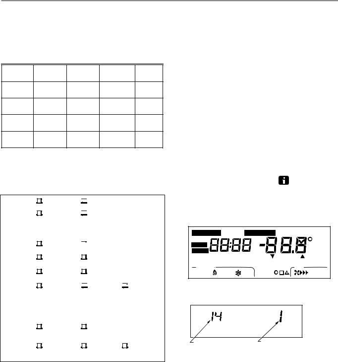
IMPORTANT
The chart Customizing Your Thermostat found in the beginning of the Owners Guide (see Fig. 9) must be completed. The homeowner identifies the options you install by referring to this chart.
Installer Setup Procedure
1. Press and hold the Information , Increase ▲, and Decrease ▼ keys at the same time until all display segments and the first setup number displays
(all display segments appear for approximately three seconds before the setup number displays). See Figs. 11 and 12.
Set Program Start Time Set Day/Time Temporary Setting Enrg
Hold for |
AM |
|
Sav |
|
Em Ht |
|
Room |
||
PM |
|
|||
Aux Ht |
|
|
||
|
|
|
Outdoor |
|
MonTueWedThuFriSatSun |
Heat Cool |
|||
WakeLeaveReturnSleep |
|
In Recovery |
Auto |
Repl Batt |
System |
|
DST |
Fan |
|
Em Heat OffCool Auto |
Wait |
|
OnAuto |
|
M17111
Fig. 10. Display of all the segments of the LCD.
INSTALLER SETUP |
FACTORY SETTING OR OTHER |
|
NUMBER DISPLAY |
CHOICE DISPLAY (COLUMN 3 |
|
(COLUMN 2 OF TABLE 3) |
OR 5 OF TABLE 3) |
M10349 |
Fig. 11. Display of Installer Setup number and option.
69-1213—1 (T8624) |
4 |
 Loading...