


 Loading...
cable
SATELLITE |
telecom |
terrestrial |
TWG850 - Residential Voice Gateway
User manual

Important Information
CAUTION
Disconnect power before servicing.
This device is intended for indoor operation only. Telephone jacks Line 1 and Line 2 must not be connected to outside wiring.
CAUTION
To ensure reliable operation and to prevent overheating, provide adequate ventilation for this modem and keep it away from heat sources. Do not locate near heat registers or other heat-producing equipment. Provide for free air flow around the Residential Voice Gateway and its power supply.
This symbol means that your inoperative electronic appliance must be collected separately and not mixed with the household waste. The European Union has implemented a specific collection and recycling system for which producers' are responsible.
This appliance has been designed and manufactured with high quality materials and components that can be recycled and reused. Electrical and electronic appliances are liable to contain parts that are necessary in order for the system to work properly but which can become a health and environmental hazard if they are not handled or disposed of in the proper way. Consequently, please do not throw out your inoperative appliance with the household waste.
If you are the owner of the appliance, you must deposit it at the appropriate local collection point or leave it with the vendor when buying a new appliance.
-If you are a professional user, please follow your supplier's instructions.
-If the appliance is rented to you or left in your care, please contact your service provider. Help us protect the environment in which we live !
NORTH AMERICAN CABLE INSTALLER:
This reminder is provided to call your attention to Article 820-40 of the National Electrical Code (Section 54 of the Canadian Electrical Code, Part 1) which provides guidelines for proper grounding and, in particular, specifies that the cable ground shall be connected to the grounding system of the building as close to the point of cable entry as practical.
Euro-PacketCable, Euro-DOCSIS, and DOCSIS compliant
This product was designed according to Euro-PacketCable Specification, Euro-DOCSIS Specifications and Data over Cable Service Interface Specifications.
ii
Operating Information
Operating Temperature: |
0˚ - 40˚ C |
(32˚ - 104˚ F) |
Storage Temperature: |
-20˚ to 70˚ C |
(-4°F to 158°F) |
If you purchased this product at a retail outlet, please read the following:
Product Information
Keep your sales receipt to obtain warranty parts and service and for proof of purchase. Attach it here and record the serial and model numbers in case you need them. The numbers are located on the back of the product.
Model No. ____________________________Serial No ________________________________
Purchase Date: ________________________Dealer/Address/Phone: _________________________
Illustrations contained in this document are for representation only. |
iii |
Table of Contents |
|
Chapter 1: Connections and Setup........................................................................................... |
1 |
Introduction ............................................................................................................................ |
1 |
Residential Voice Gateway Features ................................................................................... |
1 |
What’s on the CD-ROM ...................................................................................................... |
1 |
Computer Requirements.................................................................................................... |
3 |
Wall Mounting ................................................................................................................... |
4 |
Residential Voice Gateway TWG850 Overview........................................................................... |
5 |
Front Panel........................................................................................................................ |
5 |
Rear Panel ......................................................................................................................... |
6 |
Relationship among the Devices .............................................................................................. |
7 |
What the Modem Does ...................................................................................................... |
7 |
What the Modem Needs to Do Its Job................................................................................. |
7 |
Contact Your Local Cable Company ................................................................................... |
8 |
Connecting the Residential Voice Gateway to a Single Computer............................................ |
10 |
Attaching the Cable TV Wire to the Residential Voice Gateway ......................................... |
10 |
Important Connection Information .................................................................................. |
11 |
USB Connection to One Computer ................................................................................... |
11 |
USB Connection............................................................................................................... |
13 |
Using Windows 2000 for USB Connection ........................................................................ |
13 |
Using Windows Me for USB Connection............................................................................ |
17 |
Using Windows XP for USB Connection ............................................................................ |
18 |
Ethernet Connection to One Computer ............................................................................ |
20 |
Connecting More Than Two Computers to the Residential Voice Gateway ........................ |
21 |
Telephone or Fax Connection.......................................................................................... |
22 |
Activating the Residential Voice Gateway ............................................................................... |
23 |
iv |
|
Chapter 2: Web Configuration................................................................................................ |
24 |
Accessing the Web Configuration........................................................................................... |
24 |
Outline of Web Manager .................................................................................................. |
25 |
Gateway – Status Web Page Group ......................................................................................... |
26 |
Software.......................................................................................................................... |
26 |
Connection...................................................................................................................... |
27 |
Password......................................................................................................................... |
27 |
Diagnostics ..................................................................................................................... |
28 |
Event Log ........................................................................................................................ |
29 |
Initial Scan ...................................................................................................................... |
29 |
Gateway – Network Web Page Group ...................................................................................... |
30 |
LAN................................................................................................................................. |
30 |
WAN................................................................................................................................ |
31 |
Computers ...................................................................................................................... |
31 |
Gateway – Advanced Web Page Group .................................................................................... |
32 |
Options ........................................................................................................................... |
32 |
IP Filtering....................................................................................................................... |
33 |
MAC Filtering .................................................................................................................. |
33 |
Port Filtering ................................................................................................................... |
34 |
Forwarding...................................................................................................................... |
35 |
Port Triggers ................................................................................................................... |
36 |
RIP (Routing Information Protocol) Setup ......................................................................... |
37 |
Gateway – Firewall Web Page Group ....................................................................................... |
38 |
Web Content Filtering...................................................................................................... |
38 |
TOD Filtering................................................................................................................... |
39 |
Local Log and Remote Log............................................................................................... |
40 |
Illustrations contained in this document are for representation only. |
v |
Gateway – Parental Control Web Page Group .......................................................................... |
41 |
Basic ............................................................................................................................... |
41 |
Gateway – Wireless Web Page Group ...................................................................................... |
42 |
802.11b/g Basic.............................................................................................................. |
43 |
802.11b/g Security ......................................................................................................... |
45 |
Access Control ................................................................................................................ |
48 |
802.11b/g Advanced....................................................................................................... |
49 |
Bridging .......................................................................................................................... |
51 |
Guest Network ................................................................................................................ |
52 |
VoIP – Basic Web Page Group ................................................................................................. |
53 |
Basic LAN ........................................................................................................................ |
53 |
Hardware Info ................................................................................................................. |
53 |
Event Log ........................................................................................................................ |
54 |
CM State ......................................................................................................................... |
54 |
Chapter 3: Additional Information ......................................................................................... |
55 |
Frequently Asked Questions .................................................................................................. |
55 |
General Troubleshooting ....................................................................................................... |
57 |
FCC Declaration of Conformity and Industry Canada Information........................................... |
59 |
Service Information................................................................................................................ |
60 |
Glossary ................................................................................................................................ |
61 |
vi

Chapter 1: Connections and Setup
Chapter 1: Connections and Setup
Introduction
Residential Voice Gateway Features
zSupport Multiple Provisioning Mode
zStandard RJ-45 connector for 10/100BaseT Ethernet with auto-negotiation and MDIS functions
zUSB Connector for USB interface
zTwo RJ-11 Foreign Exchange Station (FXS) ports for IP telephony
zSupport simultaneous voice and data communications
zTwo simultaneous voice conversations in the different FXS ports with different CODEC: PCM A-law, PCM-law, G.723.1, G.729, G.729a, G.729e, G.728, G.726, BV16 and BV32
zEcho Cancellation
zVoice Active Detection (VAD)
zDTMF detection and generation
zComfort Noise Generation (CNG)
zSupport V.90 fax and modem services
zTransparent bridging for IP traffic
zRSA and 56 bit DES data encryption security
zSNMP network management support
zRemote operating firmware downloading
zSupport Web pages and private DHCP server for status monitoring
zClear LED display
zPlug and Play
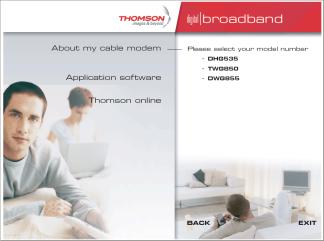
What’s on the CD-ROM
Insert the Residential Voice Gateway CD-ROM into your CD-ROM drive to view troubleshooting tips, the internal diagnostics, and other valuable information.
Note: You might need to use the CD-ROM to install the USB driver if you are connecting via the USB port.
Illustrations contained in this document are for representation only. |
1 |
Chapter 1: Connections and Setup
CD-ROM Contents:
zElectronic copy of this user’s guide in additional languages (PDF format)
zAdobe Acrobat Reader — application you can load to read PDF format, if you don’t have it loaded already
zUSB drivers — required if connecting by USB
zLinks to Thomson and RCA web sites
DOCSIS and PacketCable are trademarks of Cable Television Laboratories, Inc.
2

Chapter 1: Connections and Setup
Computer Requirements
For the best possible performance from your Residential Voice Gateway, your personal computer must meet the following minimum system requirements (note that the minimum requirements may vary by cable companies):
|
IBM PC COMPATIBLE |
MACINTOSH** |
|
|
|
CPU |
Pentium preferred |
PowerPC or higher |
|
|
|
System RAM |
16MB (32MB preferred) |
24MB (32MB preferred) |
|
|
|
Operating System |
Windows* NT/2000/Me/XP, |
Mac OS** 7.6.1 or higher |
|
Linux |
|
|
|
|
Available Disk Space |
125MB |
50MB |
|
|
|
Sound Card |
Required for audio on CD-ROM |
N/A |
|
|
|
Video |
VGA or better (SVGA preferred) |
VGA or better (SVGA built-in preferred) |
|
|
|
CD-ROM Drive |
Required |
Required |
|
|
|
Ethernet |
10BaseT or 100BaseT |
10BaseT or 100BaseT |
|
An Ethernet card makes it possible for your computer to pass data to |
|
|
and from the internet. You must have an Ethernet card and software |
|
|
drivers installed in your computer. You will also need a standard |
|
|
Ethernet cable to connect the Ethernet card to your Residential Voice |
|
|
Gateway. |
|
|
|
|
USB Port |
USB (Windows 2000/ME/XP only) |
|
|
The Universal Serial Bus is a high speed bus that enables your |
|
|
computer to communicate simultaneously with a variety of |
|
|
peripherals. However, if you have other peripherals that send and |
|
|
receive a lot of information, such as speakers, printers or scanners, we |
|
|
recommend using an Ethernet card to support this modem. |
|
|
• A TCP/IP network protocol for each machine |
|
Software |
||
|
• Microsoft Internet Explorer 4.0 or later or Netscape Navigator 4.0 or |
|
later. (5.0 and 4.7 or later, respectively, are strongly recommended.)
*Windows is a trademark of Microsoft Corporation.
**Macintosh and the Mac OS are trademarks of Apple Computer, Inc.
Illustrations contained in this document are for representation only. |
3 |
Chapter 1: Connections and Setup
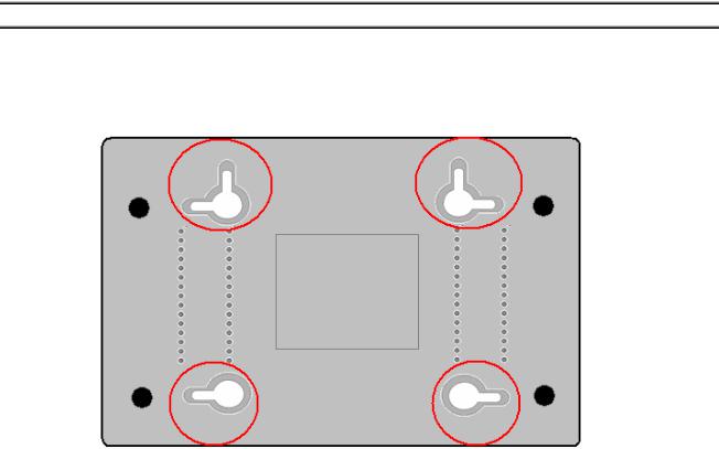
Wall Mounting
The number of the screw: 2 pcs
Direction for wall mounting: LED panel upward.
Dimension for the screw: TBD
There are 4 slots on the underside of the EMTA that can be used for wall mounting.
Note: When wall mounting the unit, ensure that it is within reach of the power outlet.
You will need 2 suitable screws which screw diameter would be 4.4 mm to wall mount the Cable Modem or the Battery Pack. Two different wall mount directions could be chosen for the Battery Pack.
To do this:
1.Ensure that the wall you use is smooth, flat, dry and sturdy and use the 4 screw holes which are 101.6 mm apart from each other.
2.Fix the screws into wall, leaving their heads 3 mm (0.12 inch) clear of the wall surface.
3.Remove any connections to the unit and locate it over the screw heads. When in line, gently push the unit on to the wall and move it downwards to secure.
4
Chapter 1: Connections and Setup
Residential Voice Gateway TWG850 Overview
Front Panel
The following illustration shows the front panel of the TWG850 machine:
The LEDs on the front panel are described in the table below (from left to right):
|
Tel 2 |
Tel 1 |
WirelessMessage |
Cable |
Cable |
PC |
Internet |
Description |
||
|
|
|
|
|
|
Activity |
Link |
Link |
|
|
|
X |
X |
X |
|
OFF |
OFF |
OFF |
OFF |
FLASH |
Tuning |
|
|
|
|
|
|
|
|
|
|
(Searching downstream signal) |
|
|
|
|
|
|
|
|
|
|
Ranging - Awaiting Response |
|
X |
X |
X |
|
OFF |
OFF |
OFF |
FLASH |
FLASH |
|
|
|
(DS carrier acquire, ranging in process but RNG-RSP has |
||||||||
|
|
|
|
|
|
|
|
|
|
not been detected) |
|
X |
X |
X |
|
OFF |
OFF |
OFF |
FLASH |
FLASH |
Any RNG-RSP detected |
Start-up |
|
|
|
|
|
|
|
|
|
(Normalizing power level and timing offset) |
|
|
|
|
|
|
|
|
|
Connecting |
|
Operation |
X |
X |
X |
|
OFF |
OFF |
FLASH |
FLASH |
FLASH |
|
|
|
|
|
|
|
|
|
|
|
(Ranging complete, DHCP in progress) |
|
X |
X |
X |
|
OFF |
FLASH |
FLASH |
FLASH |
FLASH |
Configuring (DHCP complete, configuration file download |
|
|
|
|
|
|
|
|
|
|
in process) |
|
X |
X |
X |
|
FLASH |
FLASH |
FLASH |
FLASH |
FLASH |
Registering and Baseline Privacy Initializing |
|
|
(configuration file download complete, initialize BPI if BPI is |
||||||||
|
|
|
|
|
|
|
|
|
|
ON, registration in process) |
|
X |
X |
|
|
Enter Normal Operation Mode |
|
Registration complete |
|||
|
X |
X |
X |
|
X |
X |
X |
X |
FLASH |
NO Cable Link |
|
|
ON |
CM is registered |
|||||||
|
|
|
|
|
|
|
|
|
||
|
X |
X |
X |
|
X |
X |
X |
OFF |
X |
NO Ethernet/USB carrier present |
|
|
FLASH |
Ethernet/USB TX/RX traffic |
|||||||
|
|
|
|
|
|
|
|
ON |
|
Ethernet/USB carrier present, no traffic |
|
X |
X |
X |
|
X |
X |
OFF |
X |
X |
NO Cable Link |
|
|
FLASH |
Cable BSS/OSS has set the CM into de-activated state |
|||||||
Normal |
|
|
|
|
|
|
ON |
|
|
CM is registered |
|
|
|
|
|
OFF |
|
|
|
Internet ON-OFF switch off/No RF DS/US network traffic |
|
Operation |
X |
X |
X |
|
X |
X |
X |
X |
||
|
FLASH |
RF DS/US network traffic |
||||||||
|
|
|
|
|
|
|
|
|
||
|
|
|
|
|
OFF |
|
|
|
|
No message is delivered by the MSO |
|
X |
X |
X |
|
FLASH |
X |
X |
X |
X |
Email/Voice Mail is available for the user on the server |
|
|
|
(Implementation of the message waiting LED will be via |
|||||||
|
|
|
|
|
|
|
|
|
|
|
|
|
|
|
|
|
|
|
|
|
Proprietary MIB) |
|
X |
X |
OFF |
|
X |
X |
X |
X |
X |
Wireless initiate fail or disable |
|
ON |
|
Wireless initiate success or enable |
|||||||
|
|
|
FLASH |
|
|
|
|
|
|
TX/RX Wireless Traffic |
No service |
X |
X |
X |
|
X |
X |
Wink |
X |
X |
NACO =OFF |
Operation |
X |
X |
X |
|
3 seconds ON followed by a flash OFF |
BPI unauthorized (when BPI is ON) |
||||
MTA |
OFF |
FLASH |
|
|
|
|
|
|
|
MTA DHCP |
FLASH |
OFF |
|
|
|
|
|
|
|
MTA SNMP/TFTP |
|
initialization |
|
|
|
|
|
|
|
|||
FLASH |
FLASH |
|
|
<CM Normal Operation> |
|
RSIP |
||||
|
|
|
|
|||||||
MTA |
ON |
ON |
|
|
|
Both Lines On-Hook |
||||
ON |
FLASH |
|
|
|
|
|
|
|
Tel1 Off-hook, Tel2 On-hook |
|
Operation |
FLASH |
ON |
|
|
|
|
|
|
|
Tel1 On-hook, Tel2 Off-hook |
|
FLASH |
FLASH |
|
|
|
|
|
|
|
Both Lines Off-Hook |
SW |
X |
X |
X |
|
FLASH |
FLASH |
FLASH |
FLASH |
FLASH |
A software download and while updating the FLASH |
Download |
X |
X |
X |
|
|
From Right to Left |
|
memory |
||
Operation |
|
|
|
|
||||||
|
|
|
|
|
|
|
|
|
|
|
Illustrations contained in this document are for representation only. |
5 |
Chapter 1: Connections and Setup
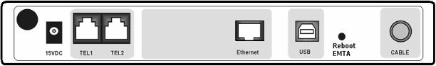
Rear Panel
15VDC: |
15V DC-IN Power connector |
TEL1 & TEL2 |
Telephony RJ-11 connector |
ETHERNET: |
Ethernet 10/100BaseT RJ-45 connector |
USB: |
USB Connector |
REBOOT EMTA: |
Reboot this Residential Voice Gateway |
CABLE: |
F-Connector |
6
Chapter 1: Connections and Setup
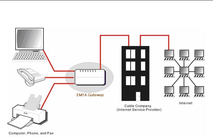
Relationship among the Devices
This illustration shows a cable company that offers DOCSISand PacketCable-compliant voice/data services.
What the Modem Does
The Residential Voice Gateway provides high-speed Internet access as well as cost-effective, toll-quality telephone voice and fax/modem services over residential, commercial, and education subscribers on public and private networks via an existing CATV infrastructure. It can inter-operate with the PacketCable compliant headend equipment and provide the IP-based voice communications. The IP traffic can transfer between the Residential Voice Gateway and DOCSIS compliant headend equipment. The data security secures upstream and downstream communications.
What the Modem Needs to Do Its Job
The Right Cable Company: Make sure your local cable company provides data services that use cable TV industry-standard Euro-DOCSIS or DOCSIS-compliant and Euro-PacketCable or PacketCable-compliant technology.
The Internet/Telephony Service Provider (ISP/TSP): Your cable company provides you access to an Internet Service Provider (ISP) and Telephony Service Provider (TSP). The ISP is your gateway to the Internet and provides you with a pipeline to access Internet content on the World Wide Web (WWW). The TSP provides you with telephony access to other modems or other telephony services over the Public Switched Telephone Network (PSTN).
Illustrations contained in this document are for representation only. |
7 |
Chapter 1: Connections and Setup
Check with your cable company to make sure you have everything you need to begin; they’ll know if you need to install special software or re-configure your computer to make your cable internet service work for you.
Contact Your Local Cable Company
You will need to contact your cable company to establish an Internet account before you can use your gateway. You should have the following information ready (which you will find on the sticker on the gateway):
•The serial number
•The model number
•The Cable Modem (CM) Media Access Control (MAC) address
•The Terminal Adapter (EMTA) MAC address
8
Chapter 1: Connections and Setup
Please verify the following with the cable company
The cable service to your home supports Euro-DOCSIS or DOCSIS compliant two-way modem access.
Your internet account has been set up. (The Media Terminal Adapter will provide data service if the cable account is set up but no telephony service is available.)
You have a cable outlet near your PC and it is ready for Cable Modem service.
Note: It is important to supply power to the modem at all times. Keeping your modem plugged in will keep it connected to the Internet. This means that it will always be ready whenever you need.
Important Information
Your cable company should always be consulted before installing a new cable outlet. Do not attempt any rewiring without contacting your cable company first.
Illustrations contained in this document are for representation only. |
9 |
Chapter 1: Connections and Setup
Connecting the Residential Voice Gateway to a Single Computer
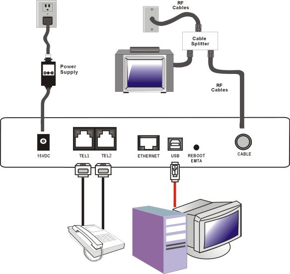
This section of the manual explains how to connect your Residential Voice Gateway to the USB or Ethernet port on your computer and install the necessary software. Please refer to Figure 1 to help you connect your Digital Cable Modem for the best possible connection.
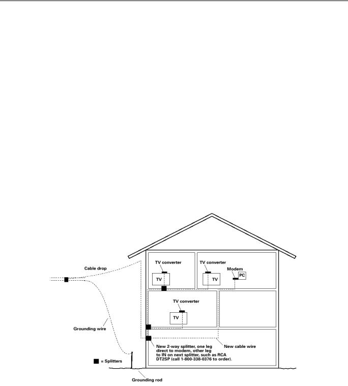
Attaching the Cable TV Wire to the Residential Voice Gateway
1.Locate the Cable TV wire. You may find it one of three ways:
a.Connected directly to a TV, a Cable TV converter box, or VCR. The line will be connected to the jack which should be labeled either IN, CABLE IN, CATV, CATV IN, etc.
b.Connected to a wall-mounted cable outlet.
c.Coming out from under a baseboard heater or other location. See Figure 1 for the wiring example.
Notes: For optimum performance, be sure to connect your Residential Voice Gateway to the first point the cable enters your home. The splitter must be rated for at least 1GHz.
Fig. 1: Basic Home Wiring
10
Chapter 1: Connections and Setup
Important Connection Information
The Residential Voice Gateway supports Ethernet and USB connections simultaneously.
Below are important points to remember before you connect the Residential Voice Gateway.
For USB connections, follow the instructions on this page.
For Ethernet connections, go to page 20.
For telephone and fax connections, go to page 22.
USB Connection to One Computer
Note: Only use the power supply provided with this unit. Using other power supplies may damage the unit.
Fig. 2: USB Connection
Illustrations contained in this document are for representation only. |
11 |
Chapter 1: Connections and Setup
If you received an Installation/Quick Start kit with the purchase of your modem, you should use the software provided in that kit. If not, the Residential Voice Gateway CD included with your modem contains the drivers and other information you need to install your Residential Voice Gateway.
12
Chapter 1: Connections and Setup
USB Connection
If you do not want to use the CD-ROM, follow instructions 1 through 5 to connect the Residential Voice Gateway to the USB port on your computer. Instructions must be followed in the order they appear.
1.Connect one end of the coaxial cable to the cable connection on the wall, and the other end to the CABLE jack on the Residential Voice Gateway.
2.Connect the plug from the AC power supply into the POWER AC ADAPTER jack on the Residential Voice Gateway and plug the power supply into an AC outlet.
3.Insert the supplied Residential Voice Gateway CD-ROM. Wait momentarily for the CD window display.
4. Close all open applications and dialog boxes, including the CD window.
Note: Some applications may interfere with your Residential Voice Gateway installation.
5.Connect one end of the USB cable to the USB port located on the back of your computer. Connect the other end of the USB cable to the USB port on the Residential Voice Gateway.
Note: Use only the power supply that accompanied this unit. Using other power supplies may damage the unit.
Next, you need to install the USB driver for your operating system.
Using Windows 2000 for USB Connection
Follow steps 6 through 14 if you have a Windows 2000 operating system:
Illustrations contained in this document are for representation only. |
13 |
Chapter 1: Connections and Setup
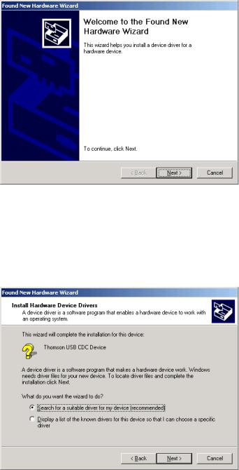
6.When the “Found New Hardware Wizard” appears, click “Next” to initiate the search for drivers for your USB device.
Note: If Windows 2000 does not recognize the presence of the Residential Voice Gateway, your BIOS settings may not permit USB and/or Plug-and-Play devices. Please contact the customer service department of the computer company.
7.Choose the “Search for a suitable driver for my device (recommended)” option, and click “Next”.
14
Chapter 1: Connections and Setup
8. Choose ONLY the “CD-ROM drives” option and click “Next”.
9.The search should find the driver for the “Thomson USB CDC Devices”. Confirm that this is the case, and click “Next” to continue and proceed to step 11; otherwise, see step 10.
Important: Do NOT continue if the search finds “USB Composite Device” driver. Proceed to step 10.
10.Follow these instructions ONLY if the driver found was NOT the “Thomson USB CDC Devices.”
A.Click “Back” to return to the previous window.
B.Ensure that you have selected the “CD-ROM” option.
C.In addition to the CD-ROM option, choose “Specify a location.” Click on “Next” to continue.
D.In the location box, key in your CD-ROM drive. For example, if your CD-ROM is located on the E: drive, type “E:\.” Click “Ok” to continue.
E.Click “Next” to continue.
F.The search should find either “RCA or Thomson USB Cable Modem”.
Illustrations contained in this document are for representation only. |
15 |
Loading...