


DTH-231-E
Table of contents
 Loading...
SERVICE MANUAL
DOCUMENTATION TECHNIQUE
TECHNISCHE DOKUMENTATION
DOCUMENTAZIONE TECNICA
DOCUMENTACION TECNICA
No copying, translation, modification on other use authorized. All rights reserved worldwide. • Tous droits de reproduction, de traduction, d'adaptation et d'exécution réservés pour tous les pays. • Sämtliche Urheberrechte an diesen Texten und Zeichnungen stehen uns zu. Nachdrucke,
Vervielfältigungen - auch auszugsweise - nur mit unserer vorherigen Zustimmung zulässig. Alle Rechte vorbehalten. • I diritti di riproduzione, di traduzione, e esecuzione sono riservati per tutti i paesi. • Derechos de reproduccion, de traduccion, de adaptacion y de ejecucion reservados para todos los paises.
WARNING : Before servicing this chassis please read the safety recommendations.
ATTENTION : Avant toute intervention sur ce châssis, lire les recommandations de sécurité.
ACHTUNG : Vor jedem Eingriff auf diesem Chassis, die Sicherheitsvorschriften lesen.
ATTENZIONE : Prima di intervenire sullo chassis, leggere le norme di sicurezza.
IMPORTANTE : Antes de cualquier intervención, leer las recomendaciones de seguridad.
Code : 357 115 40 - 0403 / 3,7M - DTH231 Print.
VIDEO
DTH231
DTH231E
DTH231U
Do not disconnect modules when they are energized!
Repairs on power supply section are to be carried out only with isolating transformer.
Ne pas retirer les modules lorsqu' ils sont sous tension. N'effectuer les travaux de maintenance sur la partie reliée
au secteur (Switch Mode) qu'au travers d'un transformateur d'isolement.
Module nicht bei eingeschaltetem Gerät entfernen!
Servicearbeiten am Netzteil nur unter Verwendung eines Regeltrenntrafos durchführen.
Non scollegare le piastre quando sono alimentate!
Per le riparazioni sulla sezione alimentatore, utilizzare un trasformatore isolatore.
No desconectar los módulos cuando están activados. Las reparaciones en la sección de alimentación de energía
deben ser ejecutadas solamente con un transformador de separación.
Indicates critical safety components, and identical components should be used for replacement. Only then can the
operational safety be garanteed.
Le remplacement des éléments de sécurité (repérés avec le symbole ) par des composants non homologués selon la
Norme CEI 65 entraine la non-conformité de l'appareil. Dans ce cas, la responsabilité du fabricant n'est plus engagée.
Wenn Sicherheitsteile (mit dem Symbol gekennzeichnet) nicht durch Original - Ersatzteile ersetzt werden, erlischt die
Haftung des Herstellers.
La sostituzione dei componenti di sicurezza (evidenziati con il segno ) con componenti non omologati secondo la
norma CEI 65 comporta la non conformitá dell'apparecchio. In tal caso è "esclusa la responsabilità " del costruttore.
La sustitución de elementos de seguridad (marcados con el simbolo ) por componentes no homologados segun la
norma CEI 65, provoca la no conformidad del aparato. En ese caso, el fabricante cesa de ser responsable.
MEASUREMENT CONDITIONS - CONDITIONS DE MESURES - MESSBEDINGUNGEN
CONDIZIONI DI MISURA - CONDICIONES DE MEDIDAS
RICEVITORE :
In UHF, livello d'entrata 1 mV, monoscopio barre :
- PAL, norma G. bianco 100%.
Via SCART, livello d'entrata 1 Vpp, monoscopio barre :
Colore, Contrasto, Luminositá media, Suono minimo.
Programma selezionato PR 01.
Tensioni continue rilevate rispetto alla massa con un voltmetro digitale.
RECEIVER :
On UHF,input level : 1 mV, bar test pattern :
- PAL, I standard, 100% white.
Via the scart socket, input level : 1 Vpp, bar test pattern :
Colour, contrast and brightness at mid-position, sound at minimum.
Programme selected : PR 01.
DC voltages measured between the point and earth using a digital
voltmeter.
EMPFÄNGER :
Bei UHF Eingangspegel 1 mV, Farbbalken :
- PAL, Norm G, Weiss 100%.
Über die Scartbuchse : Eingangspegel 1 Vss, Farbbalken :
Farbe, Kontrast, Helligkeit in der Mitte des Bereichs, Ton auf Minimum.
Zugeordnetes Programm PR 01.
Gleichspannungen mit einem digitalen Voltmeter zur Masse gemessen.
RECEPTEUR :
En UHF, niveau d'entrée 1 mV mire de barres
- SECAM, Norm L, Blanc 100%.
Par la prise Péritélévision, niveau d'entrée 1 Vcc, mire de barres .
Couleur, contraste, lumière à mi-course, son minimum.
Programme affecté PR 01.
Tensions continues relevées par rapport à la masse avec un
voltmètre numérique.
RECEPTOR :
En UHF, nivel de entrada 1 mV, mira de barras :
- PAL, norma G, blanco 100%.
Por la toma Peritelevision, nivel de entrada 1 Vpp mira de barra.
Color, Contraste, luz a mitad de carrera, Sonido minimo.
Programa afectado PR 01.
Tensiones continuas marcadas en relacion a la masa con un voltimetro digital.
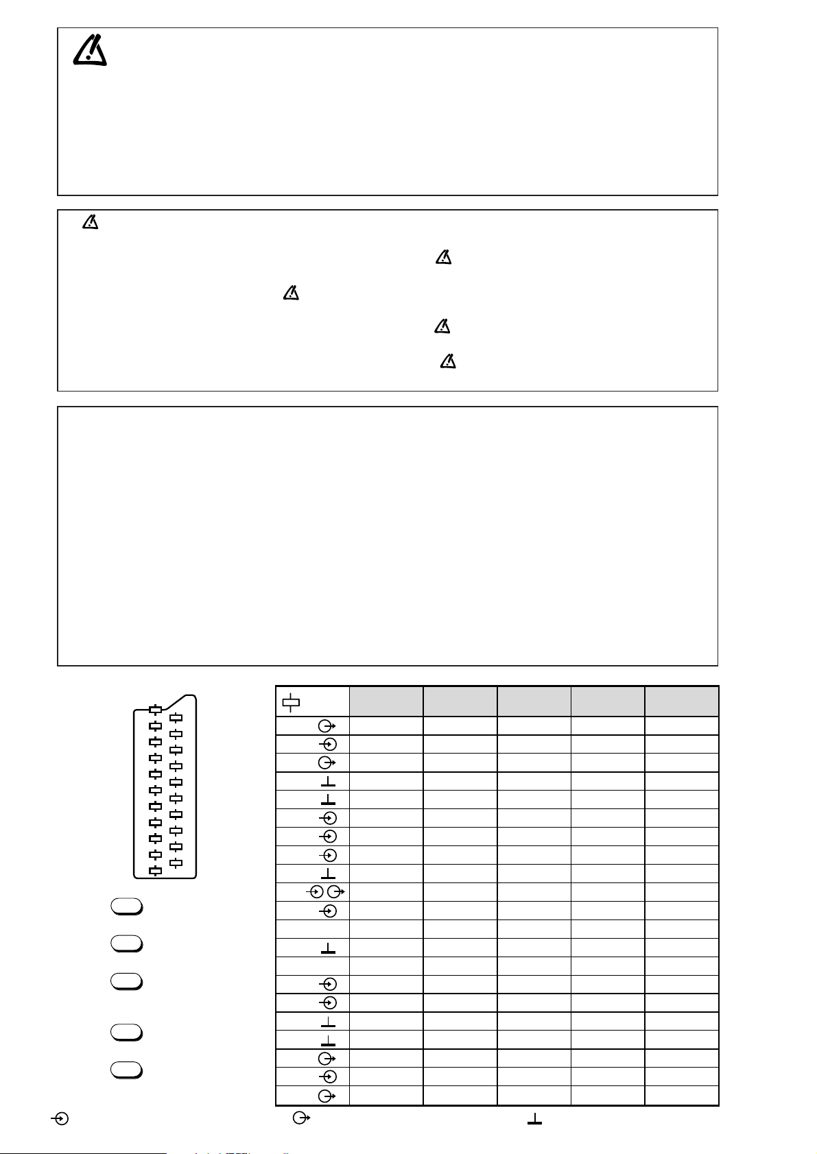
MAIN
FRANÇAIS ESPAÑOLDEUTSCHENGLISH ITALIANO
1
2
3
4
5
6
7
8
9
10
11
12
13
14
15
16
17
18
19
20
21
NC
21
17
19
15
13
20
18
16
14
12
11
9
10
8
7
5
3
1
6
4
2
NC
AUDIO "R"
AUDIO "R"
AUDIO "L"
NOTE :
... etc. identifies each
pcb module.
AUDIO "D"
AUDIO "D"
AUDIO "G"
AUDIO
"BLEU"
AUDIO "G" MONO
"BLEU"
COMMUT. LENTE
"VERT"
"VERT"
"ROUGE"
COMMUT. RAPIDE
COMMUT. RAPIDE
VIDEO
VIDEO SYNCHRO
BLINDAGE PRISE
AUDIO "R"
AUDIO "R"
AUDIO "L"
AUDIO
"BLAU"
AUDIO "L" MONO
"BLAU"
AV
UMSCHALTUNG
"GRÜN"
"GRÜN"
"ROT"
AUSTASTUNG
AUSTASTUNG
VIDEO
VIDEO ODER
SYNCHRO
ABSCHIRMUNG
DES STECKERS
AUDIO "D"
AUDIO "D"
AUDIO "I"
AUDIO
"AZUL"
AUDIO "I" MONO
AZUL
"CONMUTACION
LENTA"
"VERDE"
"VERDE"
"ROJA"
"CONMUTACION
RAPIDA"
"CONMUTACION
RAPIDA"
VIDEO
VIDEO O SINCRO
BLINDAJE
DEL ENCHUFE
AUDIO "D"
AUDIO "D"
AUDIO "S"
AUDIO
"BLU"
AUDIO "S" MONO
BLU
"COMMUTAZIONE
LENTA"
"VERDE"
"VERDE"
"ROSSO"
"COMMUTAZIONE
RAPIDA"
"COMMUTAZIONE
RAPIDA"
VIDEO
VIDEO O SINCRO
INVOLUCRO METAL-
LICO DELLA PRESA
AUDIO "L" MONO
"BLUE"
"GREEN"
AV LINK AV LINK AV LINK AV LINK AV LINK
"GREEN"
"RED"
"ROUGE" "ROT" "ROJA""ROSSO""RED"
SLOW SWITCH
FAST SWITCH
VIDEO
VIDEO VIDEO VIDEOVIDEOVIDEO
PLUG SCREEN
BOX
VIDEO OR "SYNC"
FAST SWITCH
AUDIO
"BLUE"
: OUTPUT - SORTIE - AUSGANG - USCITA - SALIDA •
: EARTH - MASSE - MASSE - MASSA - MASA
MAIN
NOTE :
... etc. repères des
platines constituant l'appareil.
MAIN
NOTA :
... etc. marcas de las
placas que constituyen el
aparato.
MAIN
NOTA :
... ecc. sigla delle
piastre dell' apparecchio.
MAIN
HINWEIS :
... usw. Kennzeichnung
der Platinen, aus denen das
Gerät zusammengesetzt ist.
: INPUT - ENTRÉE - EINGANG - ENTRATA - ENTRADA •

DTH231
First issue 04 / 03 3
CARACTERISTIQUES TECHNIQUES . . . . . . . . . . . . . . . . . . 4
MANIPULATION DU BLOQUE OPTIQUE . . . . . . . . . . . . . . . . 7
MAINTENANCE DE LA MÉCANIQUE . . . . . . . . . . . . . . . . . . 9
RÉGLAGES . . . . . . . . . . . . . . . . . . . . . . . . . . . . . . . . . . . . . . 13
SCHEMA D'INTERCONNEXION . . . . . . . . . . . . . . . . . . . . . . 15
SYNOPTIQUES
Alimentation . . . . . . . . . . . . . . . . . . . . . . . . . . . . . . . . . . 17
Asservissements . . . . . . . . . . . . . . . . . . . . . . . . . . . . . . 19
Lecteur DVD . . . . . . . . . . . . . . . . . . . . . . . . . . . . . . . . . . 21
Video et Audio . . . . . . . . . . . . . . . . . . . . . . . . . . . . . 23 - 24
Hifi . . . . . . . . . . . . . . . . . . . . . . . . . . . . . . . . . . . . . . . . . . 26
SCHEMAS
Hifi et commutations . . . . . . . . . . . . . . . . . . . . . . . . . . . . 27
Alimentation . . . . . . . . . . . . . . . . . . . . . . . . . . . . . . . . . . 29
Asservissements et Commandes / Afficheur . . . . . . . . . 31
Video . . . . . . . . . . . . . . . . . . . . . . . . . . . . . . . . . . . . . . . 33
Entrées / Sorties . . . . . . . . . . . . . . . . . . . . . . . . . . . . . . . 35
Audio numérique . . . . . . . . . . . . . . . . . . . . . . . . . . . . . . 37
MPEG . . . . . . . . . . . . . . . . . . . . . . . . . . . . . . . . . . . . . . . 39
MESURES
Alimentation et audio numérique . . . . . . . . . . . . . . . . . . 43
Audio / Vidéo (oscillogrammes) . . . . . . . . . . . . . . . . . . . 44
MPEG . . . . . . . . . . . . . . . . . . . . . . . . . . . . . . . . . . . . . . . 45
IF . . . . . . . . . . . . . . . . . . . . . . . . . . . . . . . . . . . . . . . . . . 48
Hifi et commutations . . . . . . . . . . . . . . . . . . . . . . . . . . . . 49
Audio / Vidéo (tensions) . . . . . . . . . . . . . . . . . . . . . . . . . 50
Asservissements . . . . . . . . . . . . . . . . . . . . . . . . . . . . . . 51
CIRCUITS IMPRIMES
Platine principale . . . . . . . . . . . . . . . . . . . . . . . . . . . . . . 53
MPEG . . . . . . . . . . . . . . . . . . . . . . . . . . . . . . . . . . . . . . . 55
Commandes / Afficheur et Alimentation . . . . . . . . . . . . . 57
Localisation des éléments . . . . . . . . . . . . . . . . . . . . . . . 59
ABREVIATIONS . . . . . . . . . . . . . . . . . . . . . . . . . . . . . . . . . . . 63
DATI TECNICI . . . . . . . . . . . . . . . . . . . . . . . . . . . . . . . . . . . . . 4
MANEGGIAMENTO OTTICA PICKUP . . . . . . . . . . . . . . . . . . . 7
MANUTENZIONE DELLA MECCANICA . . . . . . . . . . . . . . . . . 9
REGOLAZIONI . . . . . . . . . . . . . . . . . . . . . . . . . . . . . . . . . . . 13
DIAGRAMMA DELLE INTERCONNESSIONI . . . . . . . . . . . . 15
SCHEMA A BLOCCHI
Alimentazione . . . . . . . . . . . . . . . . . . . . . . . . . . . . . . . . . 17
Servo . . . . . . . . . . . . . . . . . . . . . . . . . . . . . . . . . . . . . . . 19
Lettore DVD . . . . . . . . . . . . . . . . . . . . . . . . . . . . . . . . . . 21
Video e Audio . . . . . . . . . . . . . . . . . . . . . . . . . . . . . . 23 - 24
Hifi . . . . . . . . . . . . . . . . . . . . . . . . . . . . . . . . . . . . . . . . . 26
SCHEMA
Hifi e commutazione . . . . . . . . . . . . . . . . . . . . . . . . . . . . 27
Alimentazione . . . . . . . . . . . . . . . . . . . . . . . . . . . . . . . . 29
Servo e Comandi / Indicatore . . . . . . . . . . . . . . . . . . . . . 31
Video . . . . . . . . . . . . . . . . . . . . . . . . . . . . . . . . . . . . . . . 33
Ingressi / Uscite . . . . . . . . . . . . . . . . . . . . . . . . . . . . . . . 35
Audio digitale . . . . . . . . . . . . . . . . . . . . . . . . . . . . . . . . . . 37
MPEG . . . . . . . . . . . . . . . . . . . . . . . . . . . . . . . . . . . . . . . 39
MISURE
Alimentazione e audio digitale . . . . . . . . . . . . . . . . . . . . 43
Audio / Video (oscillogramme) . . . . . . . . . . . . . . . . . . . . 44
MPEG . . . . . . . . . . . . . . . . . . . . . . . . . . . . . . . . . . . . . . . 45
IF . . . . . . . . . . . . . . . . . . . . . . . . . . . . . . . . . . . . . . . . . . 48
Hifi e commutazione . . . . . . . . . . . . . . . . . . . . . . . . . . . . 49
Audio / Video (tensioni) . . . . . . . . . . . . . . . . . . . . . . . . . . 50
Servo . . . . . . . . . . . . . . . . . . . . . . . . . . . . . . . . . . . . . . . 51
CIRCUITI STAMPATI
Piastra principale . . . . . . . . . . . . . . . . . . . . . . . . . . . . . . 53
MPEG . . . . . . . . . . . . . . . . . . . . . . . . . . . . . . . . . . . . . . . 55
Comandi / Indicatore e Alimentazione . . . . . . . . . . . . . . 57
Localizzazione degli elementi . . . . . . . . . . . . . . . . . . . . 59
ABBREVIAZIONI . . . . . . . . . . . . . . . . . . . . . . . . . . . . . . . . . . 63
DATOS TECNICOS . . . . . . . . . . . . . . . . . . . . . . . . . . . . . . . . . 4
MANEJO DEL CONJUNTO OPTICO . . . . . . . . . . . . . . . . . . . 7
MANTENIMIENTO DEL MECANISMO . . . . . . . . . . . . . . . . . . 9
AJUSTES . . . . . . . . . . . . . . . . . . . . . . . . . . . . . . . . . . . . . . . 13
ESQUEMA DE INTERCONEXIONES . . . . . . . . . . . . . . . . . . 15
ESQUEMA DE BLOQUES
Alimentación . . . . . . . . . . . . . . . . . . . . . . . . . . . . . . . . . . 17
Servo . . . . . . . . . . . . . . . . . . . . . . . . . . . . . . . . . . . . . . . 19
DVD . . . . . . . . . . . . . . . . . . . . . . . . . . . . . . . . . . . . . . . . 21
Vídeo y Audio . . . . . . . . . . . . . . . . . . . . . . . . . . . . . 23 - 24
Hifi . . . . . . . . . . . . . . . . . . . . . . . . . . . . . . . . . . . . . . . . . 26
ESQUEMA
Hifi y conmutación . . . . . . . . . . . . . . . . . . . . . . . . . . . . . . 27
Alimentación . . . . . . . . . . . . . . . . . . . . . . . . . . . . . . . . . 29
Servo y Mandos / Indicador . . . . . . . . . . . . . . . . . . . . . . 31
Vídeo . . . . . . . . . . . . . . . . . . . . . . . . . . . . . . . . . . . . . . . 33
Entradas / Salidas . . . . . . . . . . . . . . . . . . . . . . . . . . . . . 35
Audio digital . . . . . . . . . . . . . . . . . . . . . . . . . . . . . . . . . . . 37
MPEG . . . . . . . . . . . . . . . . . . . . . . . . . . . . . . . . . . . . . . . 39
MEDICIONES
Alimentación y audio digital . . . . . . . . . . . . . . . . . . . . . . 43
Audio / Vídeo (oscillogrammas) . . . . . . . . . . . . . . . . . . . 44
MPEG . . . . . . . . . . . . . . . . . . . . . . . . . . . . . . . . . . . . . . . 45
IF . . . . . . . . . . . . . . . . . . . . . . . . . . . . . . . . . . . . . . . . . . 48
Hifi y conmutación . . . . . . . . . . . . . . . . . . . . . . . . . . . . . 49
Audio / Vídeo (tensiones) . . . . . . . . . . . . . . . . . . . . . . . . 50
Servo . . . . . . . . . . . . . . . . . . . . . . . . . . . . . . . . . . . . . . . 51
CIRCUITOS IMPRESOS
Platina principal . . . . . . . . . . . . . . . . . . . . . . . . . . . . . . . 53
MPEG . . . . . . . . . . . . . . . . . . . . . . . . . . . . . . . . . . . . . . . 55
Mandos / Indicador y Alimentación . . . . . . . . . . . . . . . . 57
Ubicación de los componentes . . . . . . . . . . . . . . . . . . . 59
ABREVIACIONES . . . . . . . . . . . . . . . . . . . . . . . . . . . . . . . . . 63
TECHNISCHE DATEN . . . . . . . . . . . . . . . . . . . . . . . . . . . . . . . 4
HANDHABUNG DER OPTISCHEN EINHEIT . . . . . . . . . . . . . 7
WARTUNG DES LAUFWERKS . . . . . . . . . . . . . . . . . . . . . . . 9
EINSTELLUNGEN . . . . . . . . . . . . . . . . . . . . . . . . . . . . . . . . . 13
VERDRAHTUNGSPLAN . . . . . . . . . . . . . . . . . . . . . . . . . . . . 15
BLOCKSCHALTBILD
Netzteil . . . . . . . . . . . . . . . . . . . . . . . . . . . . . . . . . . . . . . 17
Servo . . . . . . . . . . . . . . . . . . . . . . . . . . . . . . . . . . . . . . . 19
DVD . . . . . . . . . . . . . . . . . . . . . . . . . . . . . . . . . . . . . . . . 21
Video Signalverarbeitung und Audio . . . . . . . . . . . . 23 - 24
Hifi . . . . . . . . . . . . . . . . . . . . . . . . . . . . . . . . . . . . . . . . . 26
SCHALTBILD
Hifi und umschaltung . . . . . . . . . . . . . . . . . . . . . . . . . . . . 27
Netzteil . . . . . . . . . . . . . . . . . . . . . . . . . . . . . . . . . . . . . . 29
Servo und Bedientel / Anzeige . . . . . . . . . . . . . . . . . . . . 31
Video Signalverarbeitung . . . . . . . . . . . . . . . . . . . . . . . . 33
Eingänge / Ausgänge . . . . . . . . . . . . . . . . . . . . . . . . . . . 35
Digital-Ton . . . . . . . . . . . . . . . . . . . . . . . . . . . . . . . . . . . . 37
MPEG . . . . . . . . . . . . . . . . . . . . . . . . . . . . . . . . . . . . . . . 39
MESSUNGEN
Netzteil und Digital-Ton . . . . . . . . . . . . . . . . . . . . . . . . . 43
Audio / Video Signalverarbeitung (oszillogramm) . . . . . . 44
MPEG . . . . . . . . . . . . . . . . . . . . . . . . . . . . . . . . . . . . . . . 45
ZF . . . . . . . . . . . . . . . . . . . . . . . . . . . . . . . . . . . . . . . . . . 48
Hifi und umschaltung . . . . . . . . . . . . . . . . . . . . . . . . . . . . 49
Audio / Video Signalverarbeitung (Spannung) . . . . . . . . 50
Servo . . . . . . . . . . . . . . . . . . . . . . . . . . . . . . . . . . . . . . . 51
LEITERPLATTE
Hauptplatine . . . . . . . . . . . . . . . . . . . . . . . . . . . . . . . . . . 53
MPEG . . . . . . . . . . . . . . . . . . . . . . . . . . . . . . . . . . . . . . . 55
Bedientel / Anzeige und Netzteil . . . . . . . . . . . . . . . . . . . 57
Lage der Bauteile . . . . . . . . . . . . . . . . . . . . . . . . . . . . . . 59
ABKÜRZUNGEN . . . . . . . . . . . . . . . . . . . . . . . . . . . . . . . . . . 63
TECHNICAL DATA . . . . . . . . . . . . . . . . . . . . . . . . . . . . . . . . . . 4
HANDLING THE OPTICAL PICKUP . . . . . . . . . . . . . . . . . . . . 7
MECANISM MAINTENANCE . . . . . . . . . . . . . . . . . . . . . . . . . 9
ADJUSTMENTS . . . . . . . . . . . . . . . . . . . . . . . . . . . . . . . . . . 13
WIRING DIAGRAM . . . . . . . . . . . . . . . . . . . . . . . . . . . . . . . . 15
BLOCK DIAGRAMS
Power supply . . . . . . . . . . . . . . . . . . . . . . . . . . . . . . . . . 17
Servocontrol . . . . . . . . . . . . . . . . . . . . . . . . . . . . . . . . . . 19
DVD Player . . . . . . . . . . . . . . . . . . . . . . . . . . . . . . . . . . . 21
Video and Audio . . . . . . . . . . . . . . . . . . . . . . . . . . . 23 - 24
Hifi . . . . . . . . . . . . . . . . . . . . . . . . . . . . . . . . . . . . . . . . . . 26
SCHEMATIC DIAGRAMS
Hifi and switching . . . . . . . . . . . . . . . . . . . . . . . . . . . . . . 27
Power supply . . . . . . . . . . . . . . . . . . . . . . . . . . . . . . . . . 29
Servocontrol and Control / Display . . . . . . . . . . . . . . . . . 31
Video . . . . . . . . . . . . . . . . . . . . . . . . . . . . . . . . . . . . . . . 33
Inputs / outpouts . . . . . . . . . . . . . . . . . . . . . . . . . . . . . . . 35
Digital Audio . . . . . . . . . . . . . . . . . . . . . . . . . . . . . . . . . . 37
MPEG . . . . . . . . . . . . . . . . . . . . . . . . . . . . . . . . . . . . . . . 39
MEASUREMENTS
Power supply and Digital Audio . . . . . . . . . . . . . . . . . . . 43
Audio / Video (oscillogrammes) . . . . . . . . . . . . . . . . . . . 44
MPEG . . . . . . . . . . . . . . . . . . . . . . . . . . . . . . . . . . . . . . . 45
IF . . . . . . . . . . . . . . . . . . . . . . . . . . . . . . . . . . . . . . . . . . 48
Hifi and switching . . . . . . . . . . . . . . . . . . . . . . . . . . . . . . 49
Audio / Video (voltages) . . . . . . . . . . . . . . . . . . . . . . . . . 50
Servocontrol . . . . . . . . . . . . . . . . . . . . . . . . . . . . . . . . . . 51
PRINTED CIRCUIT BOARD
Main board . . . . . . . . . . . . . . . . . . . . . . . . . . . . . . . . . . . 53
MPEG . . . . . . . . . . . . . . . . . . . . . . . . . . . . . . . . . . . . . . . 55
Control / Display and Power supply . . . . . . . . . . . . . . . . 57
Component location . . . . . . . . . . . . . . . . . . . . . . . . . . . . 59
ABBREVIATIONS . . . . . . . . . . . . . . . . . . . . . . . . . . . . . . . . . . 63
CONTENTS - SOMMAIRE - INHALT - SOMMARIO - SUMARIO
EN
FR
DE
IT
ES
DTH231
First issue 04 / 03 5
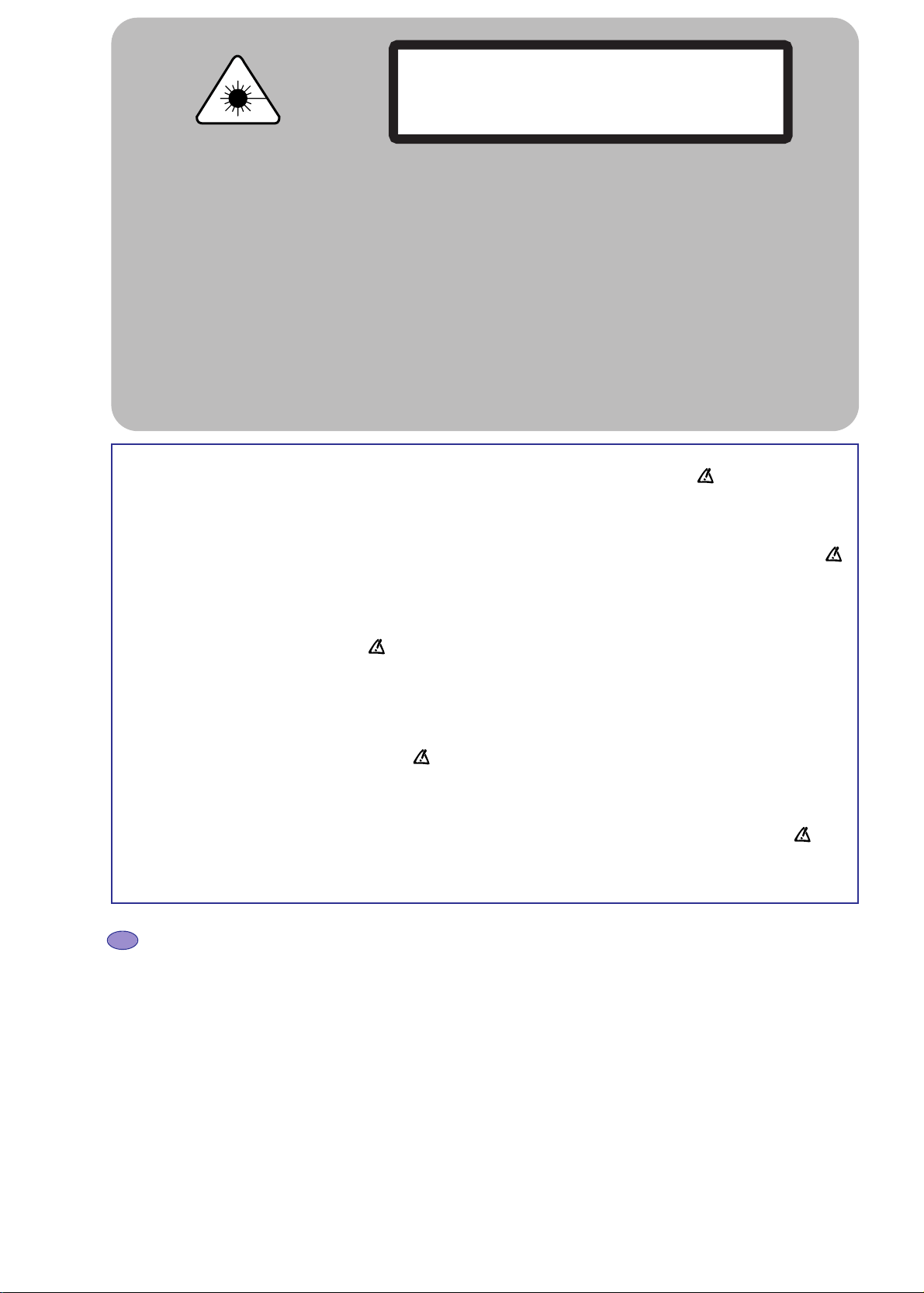
Invisible laser radiation when open and interlock
failed or defeated. Avoid direct exposure to beam.
Le rayon laser est invisible. Eviter l'exposition directe
lors de la maintenance.
Bei geöffneter Schublade und Defekt der Sicherheitsvorrichtungen besteht die Gefahr unsichtbaren
Laserlichts. Niemals direkt in den Laserstrahl sehen.
Il raggio laser è invisible. Evitare l'esposizione diretta
durante la manutenzione.
El rayo laser es invisible. Evitar la exposición directa
en el momento del mantenimiento.
DANGER :
ATTENTION :
VORSICHT BEI
REPARATUREN :
ATTENZIONE :
IMPORTANTE :
CLASS 1 LASER PRODUCT
APPAREIL A LASER DE CLASSE 1
LASER KLASSE 1
APPARECCHIO CON LASER DI CLASSE 1
APARATO CON LASER DE CLASE 1
IMPORTANT SAFETY NOTICE
There are special components used in this equipment which are imporant for safety. These part are marked by symbol on the schematic
circuit diagrams and replacement part list. It is essential that these safety critical components are replaced with the manufacture’s specified
parts to prevent electric shock, fire, or other hazards. do not attempt to modify the original design without permission of the manufacturer.
REMARQUES DE SECURITE IMPORTANTE
Il y a des composants spéciaux utilise dans cet appareil qui sont important pour la sécurité. Ces pièces sont repérées par un symbole
sur les schémas de principes et la liste de pièces détachées. Il est essentiel que ces composants de sécurité soient remplacés par les
pièces spécifiques du constructeur pour éviter les chocs électriques, feux ou autres risques. Ne tentez pas de modifier la conception
originale sans autorisation du constructeur.
WICHTIGER SICHERHEITSHINWEIS
In diesem Gerät wurden sicherheitsrelevante Komponenten verwendet. Diese Teile sind im Schaltbild und in der Ersatzteilliste mit
einem Symbol markiert. Es ist wichtig, dass diese kritischen Komponenten ausschließlich durch solche ersetzt werden, die den
Spezifikationen des Herstellers entsprechen. Die Produkthaftung des Herstellers erlischt bei Einsatz von nicht den Spezifikationen
entsprechenden Sicherheitsbauteilen und bei eigenmächtigen Schaltungsänderungen.
IMPORTANTE INFORMAZIONE DI SICUREZZA
Ci sono speciali componenti usati in questa apparecchiatura che sono importanti per la sicurezza. queste parti sono facilmente identificabili,
sullo schema e sulla lista parti, da un apposito simbolo . E’ indispensabile che questi componenti di sicurezza, nel caso di alterazioni o
guasti, vengano sostituiti con specifici ricambi originali per evitare shock elettrici, fuoco o altri rischi. Non modificare mai il circuito senza
autorizzazione della casa costruttrice.
AVISO IMPORTANTE SOBRE SEGURIDAD
En este equipo se utilizan componentes especiales que son muy importantes para la seguridad. están marcados con el símbolo en los
esquemas eléctricos y en las listas de repuestos. Es fundamental que estos componentes críticos de seguridad, sean reemplazados por las
piezas originales indicadas por el fabricante para evitar los peligros de electrocución, de fuego, etc. y no modificar el diseño original sin
autorización del fabricante.
EN Prevention of electro static discharge (esd) to Electrostatically Sensitive Devices (ESD)
Some semiconductor devices can be damaged easily by static electricity (integrated circuits, some field-effect transistors and
semiconductor chip components. The following techniques should be used to help reduce the incidence of component damage caused
by static electricity.
1. Immediately before handling any semiconductor component or semiconductor-equipped assembly, drain off any electrostatic charge
on your body by touching a known earth ground or wear a discharging wrist strap device, which should be removed for potential
shock reasons prior to applying power to the unit under test.
2. After removing an electrical assembly equipped with ESD devices, place the assembly on a conductive surface such as aluminum
foil.
3. Use only a grounded-tip soldering iron to solder or unsolder ESD devices.
4. Use only an anti-static solder removal devices.
5. Do not use freon-propelled chemicals.
6. Do not remove a replacement ESD device from its protective package until immediately before your are ready to install it.
7. Immediately before removing the protective materials from the leads of a replacement ESD device, touch the protective material to
the chassis or circuit assembly into which the device will be installed.
CAUTION : Be sure no power is applied to the chassis or circuit, and observe all other safety precautions.
8. Minimize bodily motions when handling unpackaged replacement ESD devices

DTH231
6 First issue 04 / 03
FR Prévention des composants et sous-ensembles contre les ESD ( Décharge d'Electricité Statique )
Certains semi-conducteurs peuvent être facilement endommagés par l’électricité statique (les circuits intégrés et certains transistors à
effet de champs, les composants semi-conducteurs de type chip ainsi que les diodes à émission laser équipant les lecteurs optiques ).
Les précautions suivantes doivent être utilisées pour réduire l’incidence des dommages causés par l’électricité statique.
1. Immédiatement avant de manipuler tout composant semi-conducteur ou ensemble équipé de semi-conducteurs, éliminez toute charge
électrostatique de votre corps en touchant une terre connue. Ou bien, mettez un bracelet antistatique, qui doit être retiré, pour des
raisons de choc électrique, avant de mettre l’appareil sous tension.
2. Après démontage d’un ensemble électrique équipé d’éléments sensibles aux ESD, Placez l’ensemble sur une surface conductrice telle
qu’une feuille d’aluminium.
3. N’utilisez qu’un fer à souder relier à la masse pour souder ou dessouder ces composants.
4. Pour dessouder, n’utilisez que du matériel antistatique
5. N’utilisez pas de produits chimiques à propulsion de fréon.
6. Ne retirez pas ces composants de leur emballage de protection jusqu’à ce que vous soyez prêt à l’installer.
7. Juste avant de retirer la protection des broches de ces composants, touchez la protection sur le châssis ou le circuit dans lequel le
composant va être installé.
ATTENTION : Assurez-vous que le châssis ou le circuit n’est pas sous tension, et observez toutes les autres précautions de sécurité.
8. Minimisez les déplacements corporels lorsque vous manipulez un de ces composants de remplacement déballé.
DE Vermeidung von Elektrostatischer Entladung (ESD)
Manche elektronische Komponenten wie Transistoren, Integrierte Schaltkreise oder Chipelemente können leicht durch ESD beschädigt
oder zerstört werden. Die folgenden Richtlinien helfen Schäden durch ESD zu vermeiden.
1. Unmittelbar vor dem Hantieren Halbleitern oder Baugruppen mit Halbleitern leiten Sie die statische Aufladung Ihres Körpers durch
Berühren einen geerdeten Gegenstandes ab. Beschaffen Sie sich ein leitendes Hansgelenkband. Dieses müssen Sie allerdings vor dem
Einschalten des zu prüfenden Gerätes ablegen.
2. Nach dem Ausbau einer empfindlichen elektronischen Baugruppe legen Sie diese auf einen leitende Unterlage wie Aluminium-Folie um
eine elektrostatische Entladung zu vermeiden.
3. Benutzen Sie für Lotarbeiten an empfindlichen Komponenten einen geerdeten Lötkolben.
4. Benutzen Sie antistatisches Entlötwergzeug.
5. Verwenden Sie keine Sprays, die Freon als Treibmittel enthalten. Diese können ausreichend elektrostatische Ladung erzeugen, um
empfindliche Komponenten zu schädigen.
6.
Entfernen Sie die Antistatik-Schutzverpackung (Alu-Folie, Leitgummi, Leitfolie, ..) von Komponenten und Baugruppen erst wenn Sie diese benötigen.
7. Unmittelbar vor dem Entfernen der Schutzverpackung führen Sie ein Potentialausgleich durch Berühren des Gerätes mit der
Komponente/Baugruppe durch. ACHTUNG: Stellen Sie Sicher, Dass das Gerät nicht unter Spannung steht und beachten Sie alle
einschlägigen Sicherheitsvorschriften.
8. Bewegen Sie sich beim Hantieren mit empfindlichen Komponenten/Bausteinen möglichst wenig, da die Reibung Ihrer Kleidung oder
der Füße auf dem Bodenbelag elektrostatische Ladung erzeugen kann.
IT Azioni preventive contro le scariche elettrostatiche (esd) sui Dispositivi Sensibili Elettrostaticamente (ESD)
Alcuni semiconduttoripossono essere facilmente danneggiati da elettricità statica (circuiti integrati, alcuni transistor ad effetto di campo e
componenti chip semiconduttori). Al fine di ridurre l’incidenza dei componenti danneggiati a causa di elettricità statica si dovrebbero
osservare le seguenti precauzioni.
1.
Immediatamente prima di maneggiare qualsiasi tipo di componente semiconduttore o di apparecchio che impiega semiconduttori, scaricare le
possibili cariche elettrostatiche del proprio corpo toccando un punto sicuramente collegato a terra. In alternativa, indossare un apposito braccialetto
antistatico che dovrebbe però essere tolto, per possibili potenziali shock, immediatamente prima di alimentare l’apparecchiatura sotto test.
2. Dopo il disimballo porre l’apparecchiatura equipaggiata con dispositivi ESD su una superficie conduttiva tipo foglio di alluminio.
3. Usare saldatori con punta a massa per saldare o dissaldare dispositivi ESD.
4. Usare solo saldatorI antistatici.
5. Non usare prodotti chimici tipo freon.
6. Rimuovere il dispositivo ESD dal suo imballo protettivo solo immediatamente prima del suo utilizzo.
7. Immediatamente prima della rimozione del materiale protettivo dai piedini del dispositivo ESD di ricambio, toccare con il materiale
protettivo il telaio o la massa del circuito stampato dove il dispositivo deve essere inserito.
ATTENZIONE : Assicurarsi che il circuito o il telaio non sia alimentato, e osservare tutte le altre precauzioni di sicurezza.
8. Limitare gli spostamenti quando si maneggia un dispositivo ESD disimballato.
ES Prevención contra descargas electro-státicas (esd) para los DISPOSITIVOS SENSIBLES electrostáticamente (ESD)
Algunos dispositivos semiconductores, pueden ser dañados fácilmente por la electricidad estática (los circuitos integrados, algunos
transistores de Efecto de Campo y los semiconductores "chip"). Las siguientes técnicas pueden ser utilizadas para ayudar a reducir la
destrucción de los componentes causada por la electricidad estática.
1. Inmediatamente antes de manejar cualquier componente semiconductor o conjunto equipado con semiconductores, elimine la carga
electrostática de su cuerpo tocando alguna toma de tierra conocida o utilizar una correa conductora conectada a una toma de tierra que
se pone en la muñeca la cual debe ser quitada (por razones de seguridad) antes de conectar la alimentación al equipo bajo prueba.
2. Después de quitar un conjunto equipado con componentes ESD, coloque el conjunto sobre una superficie conductora, como papel aluminio.
3. Utilizar únicamente soldadores con la punta conectada a la toma de tierra para soldar o desoldar componentes ESD.
4. Utilizar solamente soldadores antiestáticos para quitar componentes.
5. No utilizar productos químicos con gas freón como propelente.
6. No sacar de su embalaje protector el nuevo componente ESD hasta inmediatamente antes de estar todo preparado para montarlo.
7. Inmediatamente antes de quitar los materiales de protección de las patillas del componente, tocar el material protector al chasis del
conjunto donde se vaya a montar el componente.
CUIDADO : Asegúrese de que la alimentación no esté aplicada al chasis o circuito, y cumpla todas las precauciones de seguridad.
8. Maneje sin movimientos bruscos el componente ESD una vez desempaquetado.
DTH231
First issue 04 / 03 7
8
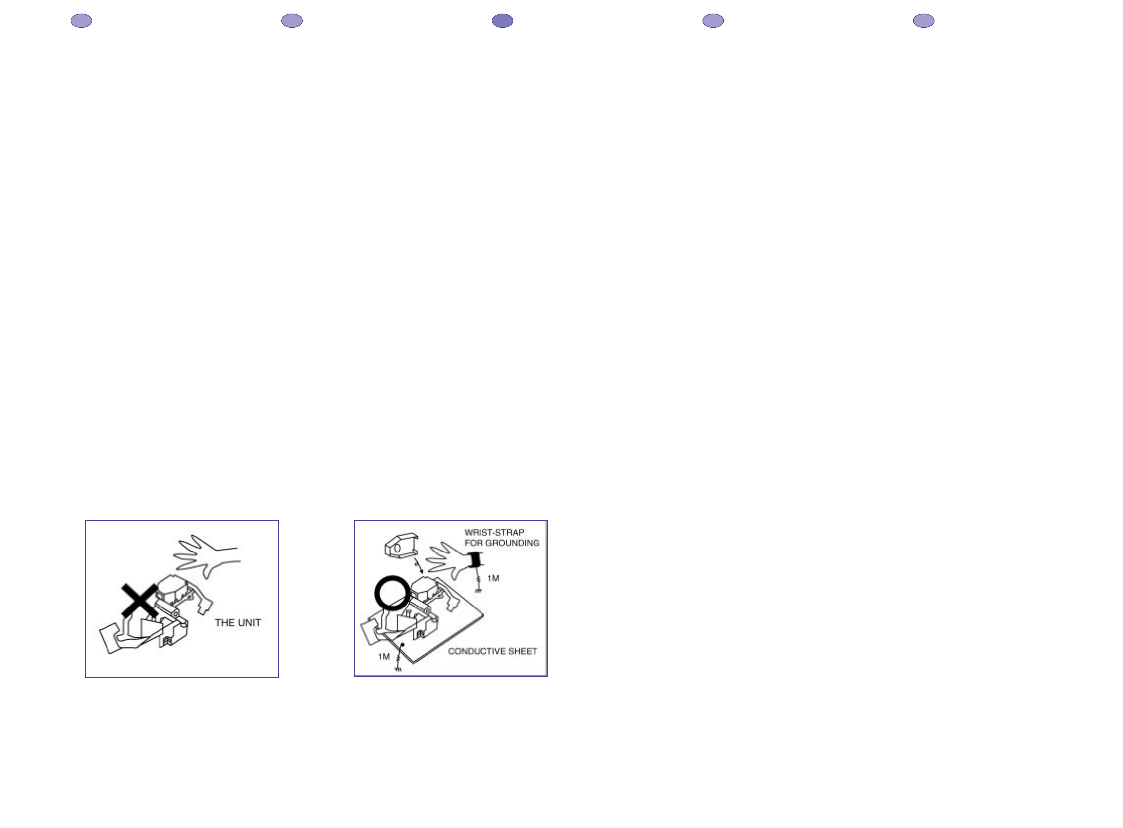
HANDLING THE OPTICAL PICKUP
The laser diode used in the optical pickup may
break down due to potential differences caused by
electricity produced by clothing or the human body,
care should therefore be taken to prevent
electrostatic discharge whilst repairing the optical
pickup.
The following method is recommended.
1) Place a conductive sheet on the work bench
(The black sheet used for wrapping repair
parts.)
2) Place the set on the conductive sheet so that
the chassis is grounded to the sheet.
3) Place your hands on the conductive sheet
(doing this gives them the same ground as the
sheet.
4) Remove the optical pickup block
5) Perform work on top of the conductive sheet. Be
careful not to let your clothes or any other static
sources to touch the unit.
* Grounding the Human Body, use an antistatic
wrist strap to discharge static electricity from
your body.
* Grounding the work place, use either an
antistatic matt or a sheet of steel on the area
where the optical pickup is to be placed and
ground the matt/sheet.
6) Short the short terminal on the PCB, which is
inside the Pickup Assembly, before
deconnecting the flexible cable for replacing the
Pickup. (The short terminal is shorted when the
Pickup Assembly is being lifted or moved.)
7) After replacing the Pickup, open the short
terminal on the PCB.
MANIPULATION DU BLOC OPTIQUE
La diode laser utilisée dans le bloc optique peut se
détériorer à cause d’une différence de potentiel
causé par l’électricité produite par les vêtements ou
le corps humain, par conséquent des précautions
doivent être prise pour éviter les décharges
électrostatiques pendant la réparation du bloc
optique.
Il est recommandé de suivre la méthode suivante.
1) Placez une feuille conductrice sur le banc de
travail (la feuille noire utilisée pour envelopper
les pièces détachées).
2) Placez l’ensemble sur la feuille conductrice pour
que le châssis soit mis à la masse par la feuille.
3) Mettez vos mains sur la feuille conductrice (en
faisant ceci, vous leur donnez la même masse
que la feuille)
4) Retirez le bloc optique
5) Travaillez en haut de la feuille conductrice.
Prenez soin de ne pas laisser vos vêtements ou
autre source statique toucher le bloc optique.
* Mise à la terre du corps humain : utilisez un
bracelet antistatique pour décharger l’électricité
statique de votre corps.
* Mise à la terre du poste de travail : placez soit
un tapis antistatique, soit
une feuille d’acier sur le banc de travail où vous
poserez le bloc optique après avoir relier le
tapis ou la feuille à la masse.
6) Pour remplacer le bloc optique, soudez le courtcircuit sur le circuit imprimé qui se trouve sur
l’ensemble optique, avant de déconnecter le
câble flexible (le court-circuit est soudé lorsque
l’ensemble optique est levé ou déplacé).
7) Après le remplacement du bloc optique,
dessoudez le court-circuit sur le circuit imprimé.
HANDHABUNG DER OPTISCHEN EINHEIT
Die verwendete Laser-Diode kann unter
Umständen zerstört werden, wenn sie mit statischer
Spannung aufgeladene Teile in Berührung kommt .
Deshalb ist unbedingt zu beachten, daß vor der
Reparatur alle Teile potentialfrei sind.
Empfehlenswert ist folgende Methode.
1) Eine leitende Unterlage auf den Werktisch
legen (über 1MOhm Widerstand geerdete
Leitgummi-Matte, Metallplatte oder ggf. die
schwarze Folie der Ersatzteilverpackung).
2) Das Gerät auf diese Fläche stellen, damit ein
Potenzialausgleich stattfinden kann.
3) Bringen Sie Ihren Körper auf das gleiche
Potenzial wie die Unterlage (z.B. mit
Handgelenkband über 1 MOhm geerdet).
4) Jetzt kann das DVD-Laufwerk bzw. die optische
Einheit ausgebaut werden .
5) Führen sie alle Arbeiten auf der LeitgummiMatte aus.
6) Zum Schutz des Lasers verbinden vor dem
Ausbau der optischen Einheit (Lösen der
Flachbandleitung) die beiden Lötpunkte auf der
Leiterplatte der optischen Einheit miteinander.
Die Leiterplatte befindet sich in der optischen
Einheit.
7) Nach dem Einbau der (neuen) optischen Einheit
den Kurzschluß wieder beseitigen !
MANEGGIAMENTO OTTICA PICKUP
Il diodo laser usato nelle ottiche pickup si può
danneggiare a causa di differenze di potenziale
causate da elettricità prodotta da vestiti o dal corpo
umano, particolari attenzioni devono essere prese,
durante la riparazione di apparecchiature con
pickup ottici, per prevenire scariche elettrostatiche.
Si raccomanda di seguire le seguenti indicazioni.
1) Mettere un foglio conduttivo sul banco di lavoro
(tipo foglio nero utilizzato per avvolgere le parti
di ricambio).
2) Posizionare l’apparecchiatura sul foglio
conduttivo per collegare la massa del telaio al
foglio conduttivo.
3) Toccare con le mani il foglio conduttivo per
avere lo stesso potenziale di massa del foglio
conduttivo.
4) Rimuovere l’assieme ottica pickup.
5) Lavorare sopra il foglio conduttivo. Evitare di far
toccare i propri vestiti o qualsiasi altra sorgente
statica all’apparecchiatura.
* Per scaricare a massa l’elettricità statica del
proprio corpo utilizzare l’apposito braccialetto
antistatico.
* Per mettere a terra il proprio posto di lavoro
utilizzare un tappetino antistatico o un foglio di
acciaio collegati a massa, sull’area dove deve
essere sostituita l’ottica.
6) In caso di sostituzione del pick up,
cortocircuitare prima gli appositi punti della
piastrina dell’assieme pickup, poi scollegare il
cavo di collegamento flessibile.
7) Aprire il cortocircuito dei terminali solo dopo la
sostituzione del Pickup.
MANEJO DEL CONJUNTO OPTICO
El diodo láser utilizado en el lector óptico puede
resultar averiado a causa de las diferencias de
potencial eléctrico producidas por el roce con la
ropa o con el cuerpo humano, también hay que
tener cuidado de que no se produzcan descargas
electrostáticas mientras se repara el lector óptico.
Se recomienda el siguiente método.
1) Colocar una hoja conductora en el banco de
trabajo (Vale la hoja negra que se utiliza para
envolver los repuestos).
2) Colocar el aparato en la hoja conductora de
forma que el chasis haga contacto con la hoja.
3) Poner las manos sobre la hoja conductora
(haciendo esto se da la misma toma de tierra
que a la hoja).
4) Retirar el conjunto óptico.
5) Realice el trabajo encima de la hoja conductora.
Tenga cuidado para no permitir que su ropa o
cualquier otra fuente de electricidad estática
pueda tocar a la unidad.
* Conecte a tierra el cuerpo humano, utilizando
una muñequera antiestática para descargar la
electricidad estática del cuerpo.
* Conectar a tierra el lugar de trabajo, utilizando
una alfombrilla antiestática o una hoja de papel
de aluminio en el área donde
se coloque el lector óptico y conectándola a la
toma de tierra.
6) Poner en cortocircuito los terminales de los
diodos (soldaduras en la cinta del conjunto
óptico) antes de desconectar el cable flexible
para remplazar el lector óptico.
7) Después de cambiar el lector óptico, quitar los
cortocircuitos anteriores.
EN FR DE IT ES
Fig. 1
Fig. 2
9
DTH231
10 First issue 04 / 03
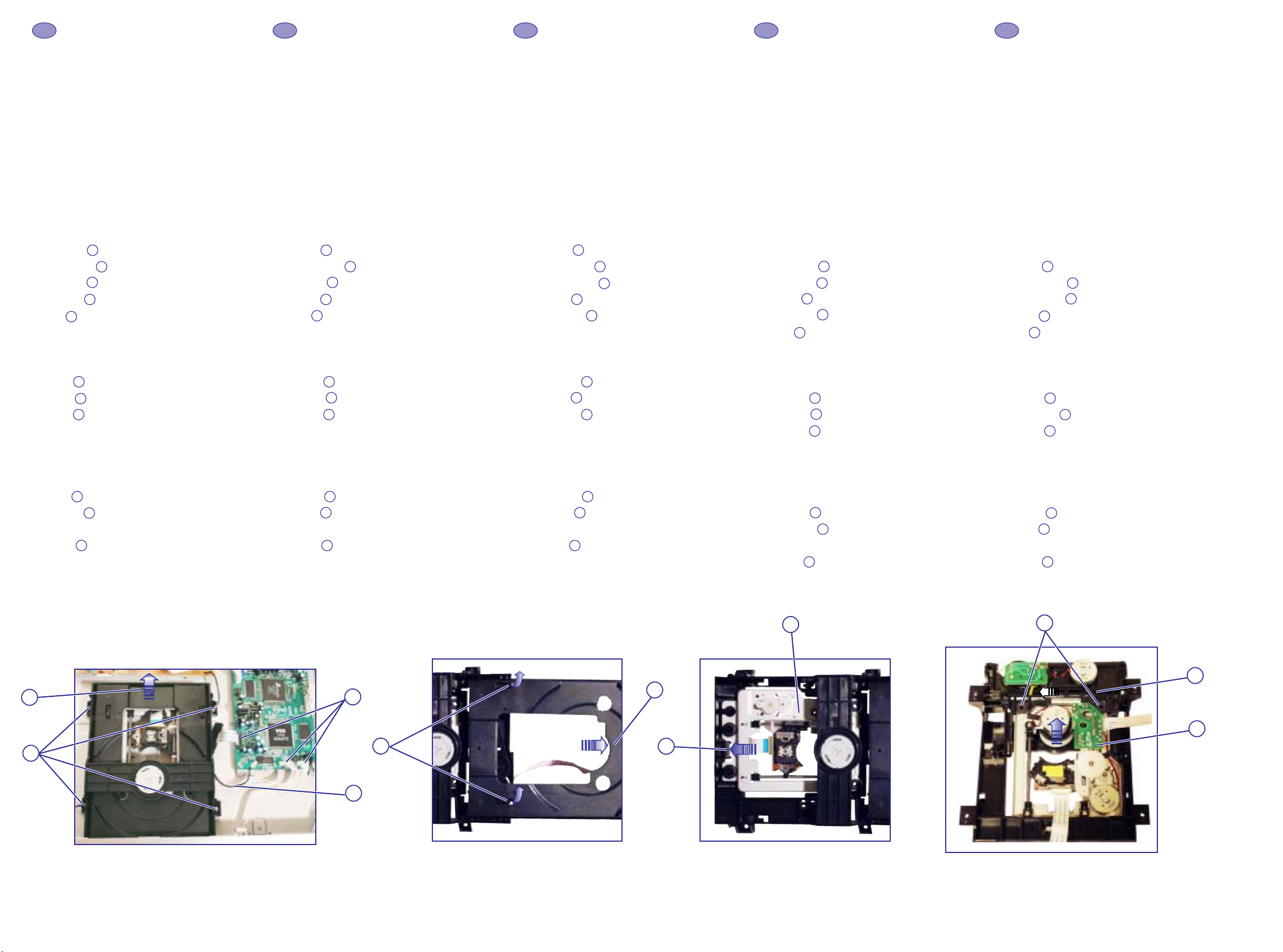
MECHANISM MAINTENANCE
In the following chapters, the reference marks of
spare parts indicate the dissassembling order. Unless
otherwise stated, reassemble in the reverse order.
REMOVAL / REFITTING
1- ACCESS TO DVD ASSEMBLY
Remove the 7 screws and the top cabinet.
2 - REMOVING THE DVD PLAYER
(fig. 1 and fig. 4)
Remove:
Disconnect:
Unscrew:
Remove:
Pull:
3 - REPLACING THE TRAY
(fig. 2 and fig. 4)
Push:
Lift up:
Push:
4 - REPLACING THE OPTICAL PICK-UP
(fig. 3 and fig. 4)
Removal:
Push:
Remove:
Refitting:
Insert:
Proceed in reverse order.
MAINTENANCE DE LA MÉCANIQUE
Dans les chapitres suivants, le repérage des pièces
indique l'ordre de démontage. Sans indication
contraire, le remontage se fait dans l'ordre inverse.
DEMONTAGE / REMONTAGE
1 - ACCES À L'ENSEMBLE DVD
Retirer les 7 vis et le coffret supérieur.
2 - DÉPOSE DE L'ENSEMBLE DVD
(fig. 1 et fig. 4)
Retirer:
Déconnecter:
Dévisser:
Retirer:
Tirer:
3 - REMPLACEMENT DU TIROIR
(fig. 2 et fig. 4)
Pousser:
Soulever:
Pousser:
4 - REMPLACEMENT DU BLOC OPTIQUE
(fig. 3 et fig. 4)
Démontage:
Pousser:
Retirer:
Remontage:
Insérer:
Procéder dans l'ordre inverse.
WARTUNG DES LAUFWERKS
In den folgenden Absätzen kennzeichnet die
Numerierung der Teile die Reihenfolge der
Demontage. Wenn nicht anders vermerkt, erfolgt
der Zusammenbau in umgekehrter Reihenfolge.
AUSBAU / EINBAU
1 - ZUGANG ZUM DVD-LAUFWERK
Entfernen Sie 7 Schrauben und den Gehäusedeckel
2 - AUSBAU DES DVD-LAUFWERKES
(Abb.1 und Abb.4)
Ausbauen:
Verbinder lösen:
Schrauben lösen:
Ausbauen:
Herausziehen:
3 - AUSTAUSCH DER SCHUBLADE
(Abb. 2 und Abb. 4)
Wegdrücken:
Heben sie:
Wegdrücken:
4 - AUSTAUSCH DER OPTISCHEN EINHEIT
(Abb. 3 und Abb. 4)
Ausbau:
Wegdrücken:
Ausbauen:
Einbau:
Einfügen:
Der Zusammenbau erfolgt in umgekehrter
Reihenfolge.
MANUTENZIONE DELLA MECCANICA
I riferimenti delle parti di ricambio, indicati nei
seguenti capitoli, si riferiscono all’ordine di
smontaggio. Dove non specificato riassemblare in
ordine inverso.
SMONTAGGIO / RIMONTAGGIO
1 - ACCESSO ALL'ASSIEME DVD
Rimuovere le 7 viti e il coperchio.
2 - RIMOVUERE IL LETTORE DVD
(fig.1 e fig.4)
Rimuovere :
Scollegare:
Svitare:
Rimuovere:
Tirare:
3 - SOSTITUZIONE DEL CASSETTO
(fig.2 e fig. 4)
Spingere:
Sollevare:
Spingere:
4 - SOSTITUZIONE DEL PICKUP
(fig. 3 e fig. 4)
Smontaggio:
Spingere:
Rimuovere:
Rimontaggio:
Inserire:
Procedere seguendo l'ordine inverso.
MANTENIMIENTO DEL MECANISMO
En los siguientes epígrafes, las marcas de
referencia de repuestos indican el orden de
desensamblaje. A no ser que se diga otra cosa, el
reensamblaje es en el orden inverso.
DESMONTAJE / MONTAJE
1 - ACCESO AL CONJUNTO DVD
Retirar los 7 tornillos y la tapa superior.
2 - RETIRAR EL DVD
(fig.1 y fig. 4)
Retirar :
Desconnectar:
Desatornillar:
Retirar:
Tirar:
3 - SUSTITUCION DE LA BANDEJA
(fig. 2 y fig. 4)
Empujar:
Hacia arriba:
Empujar:
4 - SUSTITUCION DEL CONJUNTO OPTICO
(fig. 3 y fig. 4)
Desmontaje:
Empujar:
Retirar:
Montaje:
Insertar:
Proceder en orden inverso.
11
10
09
0807060504
03
02
01
111009
080706
05
04
03
02
01
11
10
09
080706
05
04
03
02
01
11
10
09
080706
05
040302
01
11
10
09
080706
05
04
03
02
01
EN FR DE IT ES
02
11
03
06
04
Fig.1
Fig.2 Fig.3
10
Fig.4
07
05
09
01
06
DTH231
First issue 04 / 03 11
12
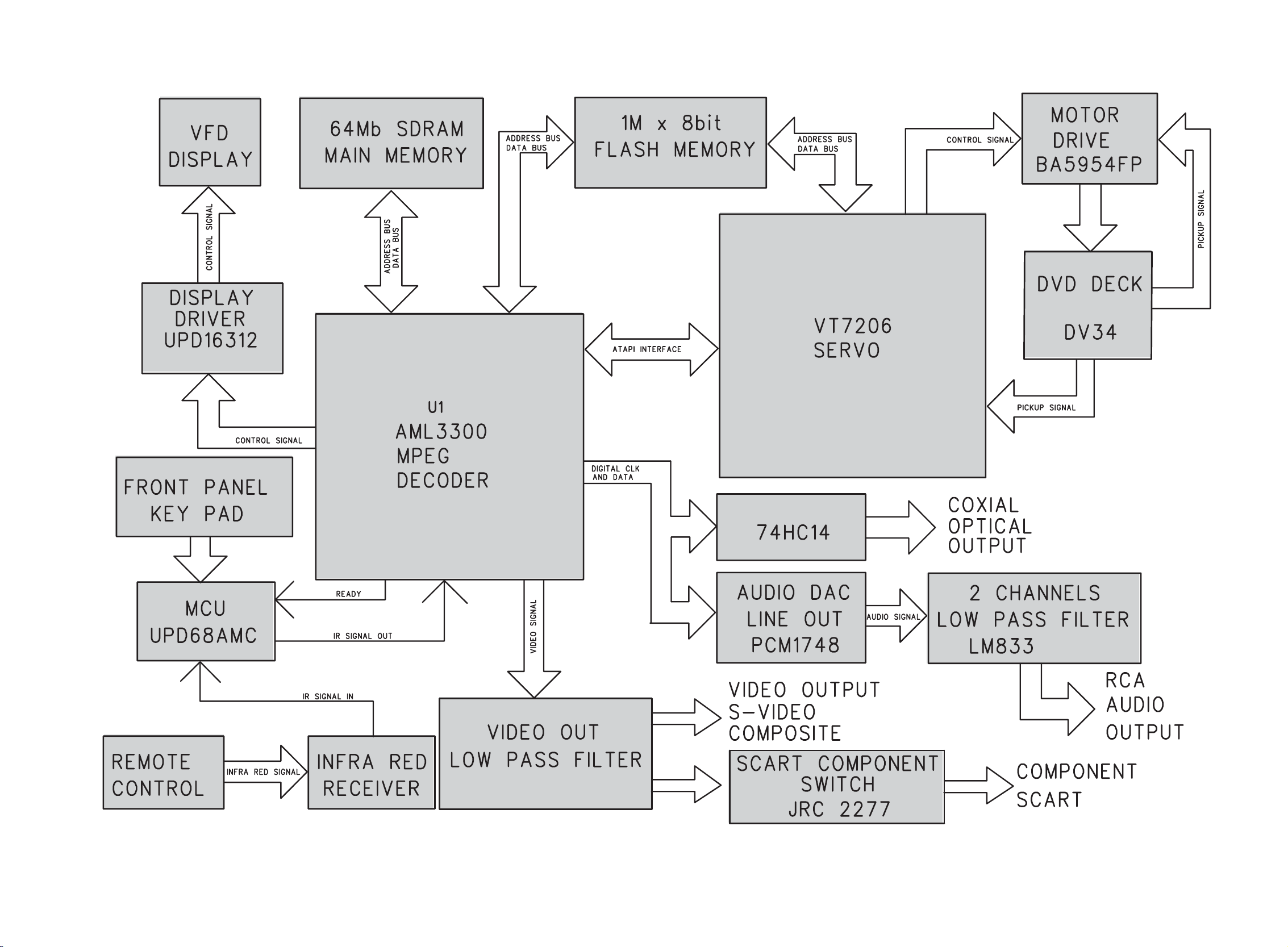
BLOCK DIAGRAM - SYNOPTIQUE - BLOCKSCHALTBILD - SCHEMA A BLOCCHI - ESQUEMA DE BLOQUES
Loading...