


MEC 2
MICROPROCESSOR
ENGINE/GENERATOR CONTROLLER
(WITH EAP 110 REMOTE ANNUNCIATOR OPTIONS)
INSTALLATION, OPERATING &
SERVICE MANUAL
Software Version 1.4
PM056 Rev 6 05/10/15
9087A – 198th Street, Langley, BC Canada V1M 3B1 Telephone (604) 888-0110 Telefax (604) 888-3381 E-Mail: info@thomsontechnology.com www.thomsontechnology.com

MEC 2 MICROPROCESSOR ENGINE/GENERATOR CONTROLLER
CONTENTS
1. |
INTRODUCTION |
1 |
|
|
1.1. |
PRODUCT REVISION HISTORY |
1 |
|
1.2. |
GENERAL DESCRIPTION |
3 |
2. |
INSTALLATION |
4 |
|
|
2.1. |
GENERAL INFORMATION |
4 |
|
2.2. |
BATTERY SUPPLY INPUT |
4 |
|
2.3. |
SPEED SENSING INPUT |
5 |
|
2.4. |
DC VOLTAGE INPUTS |
6 |
|
2.5. |
AC VOLTAGE INPUT |
6 |
|
2.6. |
AC CURRENT INPUT |
8 |
|
2.7. |
OUTPUTS |
8 |
|
2.8. |
EXTERNAL PANEL CONTROL WIRING |
8 |
|
2.9. |
REMOTE START CONTACT FIELD WIRING |
9 |
|
2.10. |
MEC MOUNTING LOCATION/INSTALLATION |
9 |
|
2.11. |
FACEPLATE MOUNTING DIMENSIONS |
10 |
|
2.12. |
MEC 2 ASSEMBLY - SIDE VIEW |
11 |
|
2.13. |
DIELECTRIC TESTING |
12 |
3. |
DESCRIPTION |
13 |
|
|
3.1. |
LEXAN FACEPLATE |
13 |
|
3.2. |
PRINTED CIRCUIT BOARD |
15 |
PM056 Rev 6 05/10/15 |
3 |
Thomson Technology |

MEC 2 MICROPROCESSOR ENGINE/GENERATOR CONTROLLER
4. |
FAULT CIRCUIT DESCRIPTIONS |
17 |
4.1. MEC 2 FUNCTIONAL BLOCK DIAGRAM |
18 |
|
4.2. |
INTERNAL FAULT CIRCUITS |
19 |
4.3. DIGITAL FAULT INPUT CIRCUITS |
20 |
|
4.4. ANALOG FAULT INPUT CIRCUITS |
21 |
|
5. |
CONTROL OUTPUT CONTACT DESCRIPTIONS |
26 |
|
|
5.1. RUN, CRANK OUTPUT CONTACTS |
26 |
|
|
5.2. |
PROGRAMMABLE OUTPUT CONTACT |
27 |
6. |
EXPANSION OUTPUT MODULE OPTION |
30 |
|
7. |
EAP 110 REMOTE ANNUNCIATOR OPTION |
34 |
|
8. |
|
OPERATING INSTRUCTIONS |
35 |
|
8.1. MEC 2 POWER-UP OPERATION SEQUENCE |
35 |
|
|
8.2. MEC 2 DISPLAY MENUS |
35 |
|
|
8.3. |
SEQUENCE OF OPERATION |
43 |
|
8.4. |
CONTROL PUSHBUTTONS |
49 |
9. |
|
PROGRAMMING INSTRUCTIONS |
50 |
|
9.1. |
SECURITY PASSWORDS |
50 |
|
9.2. |
BASIC PROGRAMMING OPERATION |
52 |
|
9.3. |
MAIN PROGRAMMING MENU |
53 |
|
9.4. ANALOG FAULT PROGRAMMING MENU |
59 |
|
|
9.5. DIGITAL FAULT PROGRAMMING MENU |
60 |
|
PM056 Rev 6 05/10/15 |
4 |
Thomson Technology |

MEC 2 MICROPROCESSOR ENGINE/GENERATOR CONTROLLER
9.6. CALIBRATION MENU |
62 |
10. |
PROGRAMMING SHEETS |
73 |
10.1. SUMMARY CONFIGURATION DATA SHEET |
73 |
|
11. |
MAIN CONFIGURATION |
74 |
11.1. ANALOG FAULT PROGRAMMING MENU |
76 |
|
11.2. DIGITAL FAULT PROGRAMMING MENU |
77 |
|
11.3. CALIBRATION MENU |
77 |
|
12. |
SPECIFICATIONS |
80 |
13. |
CONNECTION DIAGRAM |
81 |
14. |
TROUBLE SHOOTING |
82 |
15. |
NOTES |
85 |
PM056 Rev 6 05/10/15 |
5 |
Thomson Technology |

MEC 2 MICROPROCESSOR ENGINE/GENERATOR CONTROLLER
1.INTRODUCTION
1.1.PRODUCT REVISION HISTORY
The following information provides an historical summary of changes made to this product since the original release.
Software Version
1.4 05/10/15 |
Added AC protection faults Under/Over Voltage, Under/Over |
|
Frequency and Over Current |
|
Revised Idle circuit operation with digital faults #1 & 2 |
1.31 03/03/04 |
Changed Oil Pressure Sender Manufacturer requiring revised |
|
pressure/resistance calibration data |
|
New Oil Pressure Sender Thomson p/n-003654, Manufacturer- |
|
Datcon, p/n 102227. |
|
Discontinued Oil Pressure Sender Thomson p/n-000772, |
|
ManufacturerIsspro, p/n R9279C |
|
Note: The oil pressure senders are not interchangeable with the |
|
software versions. |
1.3 02/09/09 |
Added Programmable Output Feature “EPS Supplying Load” |
|
Added Digital Input Feature “No-Load Test” |
|
Added New Digital Fault Names |
|
Basin Rupture |
|
ATS in Bypass |
|
Fuel Leak |
|
Vent Damper Fail |
|
High Fuel Level |
|
Low Fuel Press |
|
Bat Charger Fail |
|
Fail to Sync |
|
HighIntkManfTemp |
|
Added Independent Programming features for AMF Outputs |
|
Added references for EAP 110 Remote Annunciator |
|
Misc. Display & Menu changes |
PM056 Rev 6 05/10/15 |
1 |
Thomson Technology |

MEC 2 MICROPROCESSOR ENGINE/GENERATOR CONTROLLER
1.2 02/01/31 |
Key changes implemented as follows: |
|
Auto Mains Failure (AMF) logic with new timers, control outputs |
|
and display features |
|
Line to Neutral AC Voltage Display on 3 Phase 4 Wire Systems |
|
(neutral connection required) |
|
Analog Shutdown Capability from Oil Pressure and |
|
Temperature Senders |
|
Expanded oil pressure operation up to 150 PSI (was 100 PSI) |
|
Single Point Calibration for Oil Pressure/engine temperature |
|
sender inputs (simplified calibration, field calibration is now |
|
mandatory) |
|
3 Additional Programmable Outputs #2, #3, #4 Enabled |
|
Programmable Output features now expanded to map to every |
|
available fault circuit |
|
Add new Programmable Output features Engine Ready & |
|
Engine Run (Fuel) |
|
Expansion Port Enabled for optional relay expansion board |
|
There were also minor changes that are reflected in the manual. |
1.1 01/07/24 |
Add “Ready to Load”; changes in temperature and pressure |
|
calibrations; extended temperature |
|
|
1.0 01/01/31 |
Original version |
|
|
Operating & Service Manual Version
Rev 6 05/10/15 |
Added AC protection faults Over/Under Voltage, Over/Under |
|
Frequency and Over Current for software version 1.4 |
|
|
Rev 5 03/03/04 |
Changed Oil pressure/resistance calibration data and new software |
|
version 1.31. |
|
|
Rev 4 02/09/09 |
Added descriptive information for new software version 1.3 |
|
|
Rev 3 02/01/31 |
Added descriptive information for new software version 1.2 |
|
|
Rev 2 01/07/25 |
Addition of “Static Precaution”; deletion of calibration jumpers to |
|
requiring external calibration resistors/potentiometers; Ready status |
|
changes to “Ready to Load”; changes in temperature and pressure |
|
calibrations; extended temperature ratings. |
|
|
Rev 1 01/02/15 |
Minor corrections. |
|
|
Rev 0 01/01/31 |
Original release. |
|
|
PM056 Rev 6 05/10/15 |
2 |
Thomson Technology |

MEC 2 MICROPROCESSOR ENGINE/GENERATOR CONTROLLER
Contact Thomson Technology, to obtain applicable instruction manuals. Soft copy of most current version is available at www.thomsontechnology.com.
1.2.GENERAL DESCRIPTION
The Thomson Technology MEC 2 Microprocessor-based Engine/Generator Controller utilizes the latest advancements in microprocessor design technology for the control and monitoring of engine-generator sets. The MEC 2 provides a comprehensive array of operational, protection and display features for automatically controlling an engine/generator set. All standard and optional features of the MEC 2 are configurable from the front panel LCD display and are security password protected. The LCD display screen prompts are in plain English, providing a user-friendly operator interface with many display options available. The microprocessor design provides high accuracy for all voltage monitoring, current monitoring and timing functions as well as providing many standard features which were previously only available as expensive add-on optional features.
The MEC 2 provides the following advanced features:
•Up to 15 alarm/shutdown fault circuits utilizing analog and digital inputs.
•Standard model meets or exceeds CSA C282, NFPA 110 Level 1 generator set control requirements.
•Backlit LCD display screen with alpha-numeric readout for display and programming.
•Digital 3-phase voltage, 3-phase current, KVA and frequency metering for generator output.
•Non-volatile memory retains logic and setpoints if control power is lost.
•Direct 3-phase voltage sensing inputs on generator supply from 120VAC up to 600VAC (nominal).
•Security password-protected programming levels.
•Self diagnostic features continuously verify processing, I/O and memory circuits.
•Superior EMI/RFI noise immunity and surge performance features as per IEEE C62.41 requirements.
•Dual microprocessor design provides independent speed sensing circuitry for higher performance.
PM056 Rev 6 05/10/15 |
3 |
Thomson Technology |

MEC 2 MICROPROCESSOR ENGINE/GENERATOR CONTROLLER
This equipment contains static-sensitive parts. Please observe the following anti-static precautions at all times when handling this equipment. Failure to observe these precautions may cause equipment failure and/or damage.
•Discharge body static charge before handling the equipment (contact a grounded surface and maintain contact while handling the equipment, a grounded wrist strap can/should also be utilized).
•Do not touch any components on the printed circuit board with your hands or any other conductive equipment.
•Do not place the equipment on or near materials such as Styrofoam, plastic and vinyl. Place the equipment on grounded surfaces and only use an anti-static bag for transporting the equipment.
2.INSTALLATION
2.1.GENERAL INFORMATION
NOTE:
Installations should be done according to all applicable electrical regulation codes as required.
The following installation guidelines are provided for general information only pertaining to typical site installations. For specific site installation information, consult Thomson Technology as required. Note: Factory installations of THOMSON TECHNOLOGY supplied control panels that have been tested and proven may deviate from these recommendations.
CAUTION!!!
All installation and/or service work performed must be done by qualified personnel only. Failure to do so may cause personal injury or death.
2.2.BATTERY SUPPLY INPUT
The MEC 2 can operate on any battery supply from 10 to 30 volts DC. The battery DC negative or common conductor must be grounded to the main generator-set frame
PM056 Rev 6 05/10/15 |
4 |
Thomson Technology |

MEC 2 MICROPROCESSOR ENGINE/GENERATOR CONTROLLER
ground. The MEC 2 is internally protected by a solid state type fuse that protects it from internal short circuits. The solid state fuse will automatically reset when the over current condition is removed. Wiring from the engine cranking battery to the control panel should conform to the following guidelines to avoid possible controller malfunction and/or damage.
2.2.1. Avoid wiring from the engine starter terminals - wiring should go directly from the battery terminals to the engine control panel (to avoid voltage drop in the starter cables and starter motor commutator noise). Note: Unit mounted control panels with short wiring runs may utilize connections from the starter terminals provided that the specific application is tested satisfactorily.
CAUTION!!!
The battery charger must be turned off before battery cables are removed from the battery (i.e. for servicing). Failure to do so may subject the control panel to an over voltage condition in which damage may result.
2.2.2.Wiring from battery to engine control panel should be two - #14 AWG (2.5mm2) wires (i.e. do not use the engine block as one of the common conductors).
2.2.3.Under noisy environments (i.e. gas engines with high voltage ignitions, etc.), wiring from battery should be a twisted pair of #14 AWG (2.5mm2) wires.
2.3.SPEED SENSING INPUT
Field wiring of the speed sensing signal wires should conform to the following guidelines to avoid possible controller malfunction and/or damage:
2.3.1.Wiring from magnetic pickup must utilize a 2 conductor shielded/twisted cable. The drain (shield) wire must be connected at the control panel end only.
2.3.2.Magnetic pickup voltage at cranking speed must be greater than 3.0VAC. At nominal speed, magnetic pickup voltage should be between 3 and 5VAC.
2.3.3.A single dedicated magnetic pickup is recommended for connection to the speed sensing input terminals. Note: One common magnetic pickup may be utilized for the system provided specific test measurements are done with the equipment installed (i.e. mag pickup voltage levels meet the required levels).
PM056 Rev 6 05/10/15 |
5 |
Thomson Technology |
MEC 2 MICROPROCESSOR ENGINE/GENERATOR CONTROLLER
2.4.DC VOLTAGE INPUTS
All DC voltage inputs to the MEC 2 are optically isolated and filtered for protection from noise spikes and transients. Input wiring must be routed so that it is not near electrically "noisy" wiring such as ignition, starter wires or main AC power conductors. All contacts must be “dry” (i.e. non-powered) and one side must be connected to the common DC negative conductor.
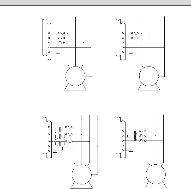
2.5.AC VOLTAGE INPUT
The MEC 2 can accept direct AC voltage input from 120-600VAC (nominal). Note: Direct input voltage sensing can only be used when the generator utilizes a single phase 3 wire or 3 phase, 4 wire distribution system with a solidly grounded neutral conductor. For 3 phase 3 wire systems (i.e. no neutral) or high voltage systems, potential transformers must be used. Refer to FIGURES #1 - 4 for voltage sensing connections. To display generator line to neutral voltage in a 3 phase 4 wire system, the neutral must be connected as shown.
PM056 Rev 6 05/10/15 |
6 |
Thomson Technology |
MEC 2 MICROPROCESSOR ENGINE/GENERATOR CONTROLLER
MEC 2 |
A B C N |
VA
VB
VC
VN
GRD
GRD
VOLTAGE INPUTS
600VAC L-L, 347VAC L-N 380VAC L-L, 220VAC L-N 480VAC L-L, 277VAC L-N 208VAC L-L, 120VAC L-N
FIGURE #1
A B C
N
GEN. GRD
3Ø, 4W 208/380/480/600VAC DIRECT SENSING SOLIDLY GROUNDED NEUTRAL SYSTEM
MEC 2 |
|
A |
B |
C |
N |
VA |
|
|
|
|
|
|
120 |
|
|
|
|
VB |
|
|
|
|
|
|
120 |
|
|
|
|
VC |
|
|
|
|
|
VN |
120 |
|
|
|
|
|
|
|
|
|
|
GRD |
GRD |
|
|
|
|
|
|
|
|
|
|
|
GRD |
|
|
|
|
SECONDARY PT VOLTAGE |
|
B |
|
|
|
208VAC L-L, 120VAC L-N |
A |
C |
|
||
|
|
||||
120VAC L-L, 69VAC L-N |
|
|
|
|
|
|
|
|
GEN. |
N |
|
|
|
|
|
|
|
FIGURE #3
3Ø, 4W WYE PT's
MEC 2 |
L1 L2 |
N |
VA
VB
VC
No Connection
VN
GRD
GRD
VOLTAGE INPUTS |
L1 L2 |
|
|
240VAC L-L, 120VAC L-N |
|
||
Note: L1 and L2 phase |
|
|
|
voltages must be 120Vac |
|
N |
|
when referenced to common |
GEN. |
||
GRD |
|||
neutral. (Delta connected |
|
|
|
generators required PTs as per |
|
|
|
figure#3 & no phase C PT) |
|
|
FIGURE #2
1Ø, 3W 120/240VAC DIRECT SENSING SOLIDLY GROUNDED NEUTRAL SYSTEM
MEC 2 |
A B C |
VA |
|
VB |
120 |
VC |
GRD 120 |
VN
No Connection
GRD
GRD
SECONDARY PT VOLTAGE |
|
B |
|
|
120VAC L-L |
A |
C |
||
|
||||
(NO NEUTRAL) |
|
|
|
N
GEN.
FIGURE #4
3Ø, 3W DELTA PT's
G:\ENGINEER\PRODUCTS\MEC2\MEC2_08.VSD REV. 1 02/01/23
PM056 Rev 6 05/10/15 |
7 |
Thomson Technology |

MEC 2 MICROPROCESSOR ENGINE/GENERATOR CONTROLLER
2.6.AC CURRENT INPUT
Current transformers (CT’s) must be used to supply the MEC 2 current inputs. CT polarity is not critical for correct circuit operation. Note: The CT secondary common conductors must be externally grounded for correct operation. CT’s must be rated for a minimum of 1.5VA output at the specified accuracy.
CAUTION!!!
When installing or performing any service work on CT circuits, always deenergize the system before proceeding with any work. Never open circuit an energized CT as extreme high voltages may result which may cause serious injury or death.
2.7.OUTPUTS
All outputs from the MEC 2 are relay driven contacts. Relay contacts have a 10A/240VAC resistive (3 Amp inductive 0.4pf), 8A/24Vdc rating and are isolated Form A & Form C types. Interposing relays are recommended between the MEC 2 outputs and end devices to prevent internal damage due to possible excessive current draw and/or damage should an external fault occur. Note: These outputs will require external over current protection (Maximum 10 Amp).
The use of AC or DC operated solenoids or relays in control systems can sometimes cause high voltage spikes on the DC power supply, which may cause electronic devices to fail. Transient suppression devices are recommended for all inductive devices sharing wiring or if physically located near engine/generator control panels. For DC operated relays or solenoids, use a suitably rated counter EMF Diode (or commonly known as “freewheeling” diode). For AC operated relays or solenoids, use a suitably rated metal oxide varistor (MOV) or capacitor/resistor suppressor.
2.8.EXTERNAL PANEL CONTROL WIRING
As a minimum, all control wiring shall conform to the local regulatory authority on electrical installations. Specific wire sizes for typical circuits (of distances up to 100ft (30m) ) are as follows:
2.8.1. Battery Control Power
2.8.2. Engine Alarm/Shutdown Contacts
2.8.3. Remote Start Contact for Transfer Switch
PM056 Rev 6 05/10/15 |
8 |
Thomson Technology |

MEC 2 MICROPROCESSOR ENGINE/GENERATOR CONTROLLER
2.8.4. |
Crank & Preheat Output Wiring |
#14 AWG (2.5mm2) (To pilot |
|
|
relays) |
2.8.5. Speed Sensing Wiring |
#16 AWG (1.5mm2) 2 |
|
|
|
Conductor Shielded Cable |
2.8.6. |
Metering Voltage Inputs |
#16 AWG (1.5mm2) |
2.8.7. |
Metering Current Inputs (from CT’s) |
#14 AWG (2.5mm2) |
For distances exceeding 100 Ft. (30m) consult Thomson Technology.
For unit mounted control panels, wire sizes may be reduced to the next smallest wire size available.
2.9.REMOTE START CONTACT FIELD WIRING
Field wiring of a remote start contact from a transfer switch to a control panel should conform to the following guidelines to avoid possible controller malfunction and/or damage.
2.9.1.Remote start contact wires (2 - #14 AWG (2.5mm2) should be run in a separate conduit.
2.9.2.Avoid wiring near AC power cables to prevent pick-up of induced voltages.
2.9.3.An interposing relay may be required if field wiring distance is excessively long (i.e. greater than 100 feet (30m) and/or if a remote contact has a resistance of greater than 5.0 ohms.
2.9.4.The remote start contact must be voltage free (i.e. dry contact). The use of a “powered” contact will damage the engine controller.
2.10.MEC MOUNTING LOCATION/INSTALLATION
The MEC 2 Engine-generator controller is designed for mounting directly onto a control panel door. Considerations should be given for the following:
•The controller should be installed in a dirt free, dry location away from extreme heat sources.
•The LCD window should be installed at an optimum height for operator viewing.
•Adequate space should be provided around the rear of the MEC 2 circuit board for control wiring.
•Verify that the intended AC voltage input to the controller does not exceed the maximum allowable level on the control panel door as per the applicable control panel certification standard.
PM056 Rev 6 05/10/15 |
9 |
Thomson Technology |
MEC 2 MICROPROCESSOR ENGINE/GENERATOR CONTROLLER
The MEC 2 controller can be installed onto a door of a control panel using one of the following methods:
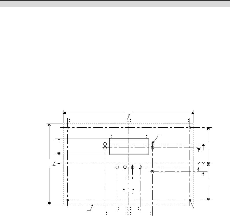
•The first method requires a special door cutout for the LCD display and LED’s as shown in FIGURE #6. This mounting method requires the lexan faceplate to be mounted directly onto the door of the control panel. The controller must be disassembled to mount on the door, then re-assembled. Refer to FIGURE #7 for correct assembly location of all parts.
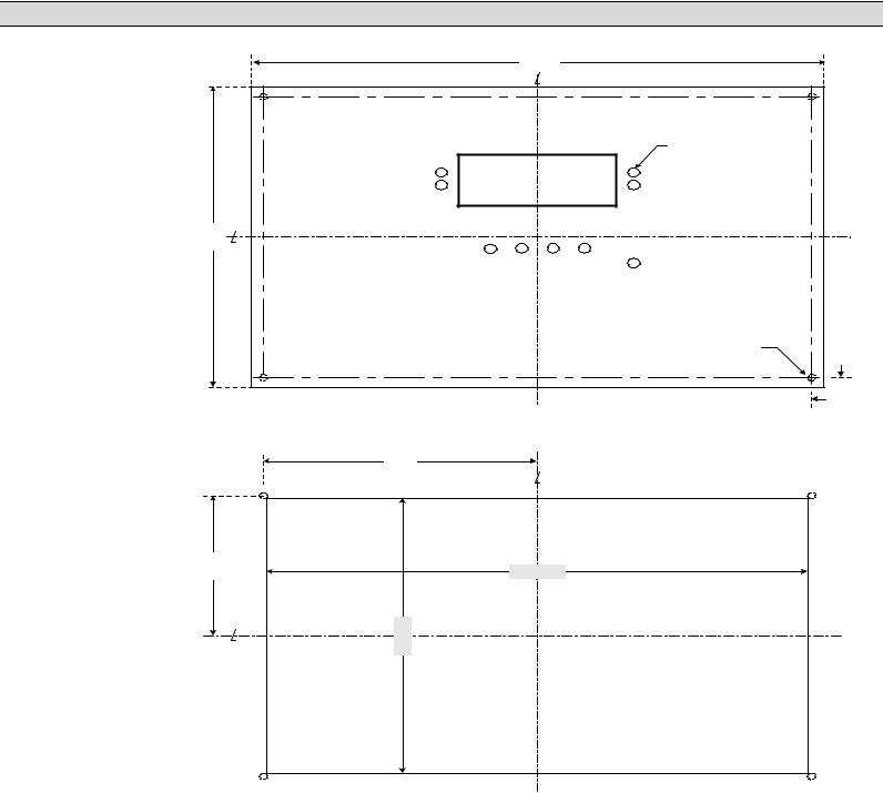
•The second method of controller mounting requires a factory supplied adapter faceplate as shown in FIGURE #8. This method only requires a single large rectangular hole to be cut out of the door as shown in FIGURE #9.
2.11.FACEPLATE MOUNTING DIMENSIONS
166 mm.
C
20 mm. 32 mm.
268 mm.
C TOP
 126 mm.

 126 mm.
9 HOLES
 80 mm.
 6 mm. DIAMETER
(1/4" DRILL)
CUTOUT
8 mm. |
|
|
|
8 mm. |
|
|
|
||
|
|
|
||
|
||||
|
|
|
|
|
|
|
|
|
|
75 mm.
|
|
|
|
41mm. |
|
|
33 mm. |
|
|||||
|
|
|
|
|
||
|
|
|
|
|
|
|
|
|
|
|
|
|
|
7 mm.
16.5 mm.
75 mm.
OUTLINE OF PRINTED CIRCUIT |
BOARD UNDER PANEL DOOR |
 24 mm.

 24 mm.
 49 mm.
 49 mm.
4 HOLES |
4 mm. DIAMETER |
(3/16" DRILL) |
G:\ENGINEER\PRODUCTS\MEC20_07.VSD
FIGURE #6
PM056 Rev 6 05/10/15 |
10 |
Thomson Technology |

MEC 2 MICROPROCESSOR ENGINE/GENERATOR CONTROLLER
2.12. MEC 2 ASSEMBLY - SIDE VIEW
MEC 2 ASSEMBLY – SIDE VIEW
FRONT |
PANEL DOOR |
|
MEC 2 PCB |
PEM STUD 
 #8-32 × 1"
1/2" NYLON SPACER (#8-32 CLEARANCE UNTHREADED)
HIGH VOLTAGE MYLAR BARRIER (mounts on bottom right hand corner, as viewed from rear)
REAR
 MEC 2 REAR COVER
#8-32 × 3/8" MACHINE SCREW
# 8-32 INTERNAL TOOTH LOCK WASHER
1.25" ALLUMINUM STANDOFF (HEX) #8-32 THREAD
#8-32 INTERNAL TOOTH LOCK WASHER
G:\ENGINEER\PRODUCTS\MEC2\MEC2_09.VSD Rev. 0 00/12/11
FIGURE #7
Notes:
1.Ensure that all lockwashers are installed as shown above.
2.The high voltage mylar barrier (P/N TMW;10805;1) must be installed as shown when the MEC 2 is installed onto the door of a control panel.
3.When the MEC 2 is installed on a door without 1” PEM studs, 1” machine screws must be used.
PM056 Rev 6 05/10/15 |
11 |
Thomson Technology |
MEC 2 MICROPROCESSOR ENGINE/GENERATOR CONTROLLER
|
|
11.5 in |
TOP |
|
|
C |
|
|
|
|
9 HOLES |
|
|
|
1/4" DIAMETER |
|
|
CUTOUT |
|
in |
C |
|
|
7.5 |
|
|
|
|
|
|
|
|
|
|
4 STUDS #8/32 |
|
|
|
1/4" |
|
|
|
1/4" |
|
|
FIGURE #8: ADAPTER FACEPLATE |
|
|
|
5.5 in |
|
|
|
C |
|
3.5 in |
|
10.875 in |
|
|
C |
in |
|
|
6.875 |
|
|
|
|
|
|
FIGURE #9: DOOR CUTOUT FOR ADAPTER FACEPLATE
G:\ENGINEER\PRODUCTS\MEC20_11.VSD Rev. 1 00/07/13
2.13.DIELECTRIC TESTING
Do not perform any high voltage dielectric testing on the control panel with the MEC 2 connected in the circuit as serious damage will occur to the controller. All AC control fuses connected to the MEC 2 must be removed if high voltage dielectric testing is performed on the control panel.
PM056 Rev 6 05/10/15 |
12 |
Thomson Technology |
MEC 2 MICROPROCESSOR ENGINE/GENERATOR CONTROLLER
3.DESCRIPTION
The MEC 2 controller consists of three parts; a Lexan faceplate which is mounted externally on the enclosure door, a printed circuit board (PCB) which is mounted inside the enclosure door, and a rear cover for the PCB.
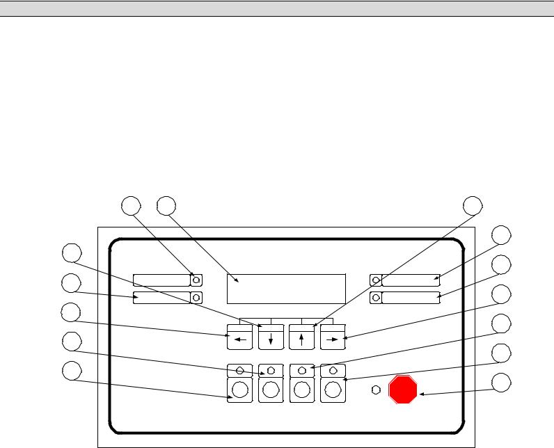
3.1.LEXAN FACEPLATE
The Lexan faceplate is shown as in FIGURE #10. The Lexan pushbuttons are connected to the main PCB via plug-in ribbon cable. The main features of the Lexan faceplate are described as follows with reference to FIGURE #10.
13 |
1 |
|
|
|
|
|
|
4 |
|
|
|
|
|
|
|
|
|
|
11 |
3 |
|
MEC 2 |
|
|
|
|
|
|
12 |
|
|
MICROPROCESSOR ENGINE CONTROLLER |
|||||||
14 |
|
ALARM |
|
|
|
|
|
READY |
|
|
|
|
|
|
|
|
|
5 |
|
|
|
SHUTDOWN |
|
|
|
|
|
SPEED SIGNAL |
|
2 |
|
|
SILENCE |
LAMP TEST |
RESET |
|
|
8 |
|
|
|
EXIT |
DECREMENT |
INCREMENT |
ENTER |
|
|||
7 |
|
|
|
|
|
|
|
|
9 |
|
|
|
|
|
|
|
|
|
|
6 |
|
|
|
|
|
|
|
|
10 |
|
|
RUN |
|
OFF |
AUTO |
|
LOAD |
EMERGENCY |
|
|
|
|
|
TEST |
STOP |
|
|||
|
|
|
|
|
|
|
|
||
MEC2_03.VSD |
Rev. 0 00/12/11 |
|
|
|
|
|
|
|
|
FIGURE #10
LCD viewing window. The LCD display is mounted on the main PCB that is visible through the lexan faceplate viewing window.
EXIT pushbutton. The EXIT function is used to scroll backwards through the status menus or programming prompts to the previous item. The EXIT function is used to “exit” the programming menu by holding this button down for approximately 2 seconds while in the programming mode.
DECREMENT pushbutton. The DECREMENT function is used to change a programming value while in the programming mode. When this pushbutton is
PM056 Rev 6 05/10/15 |
13 |
Thomson Technology |

MEC 2 MICROPROCESSOR ENGINE/GENERATOR CONTROLLER
held down, the displayed value will be “decremented” to a lower value as desired. Note: The longer the pushbutton is held down, the faster the value will be decremented.
INCREMENT pushbutton. The INCREMENT function is used to change a programming value while in the programming mode or to select a desired programming menu loop. When this pushbutton is held down, the displayed value will be “incremented” to a higher value as desired. Note: The longer the pushbutton is held down, the faster the value will be incremented.
ENTER pushbutton. The ENTER function is used to scroll forwards through the status menus or programming prompts to the next item. The ENTER function is used to “enter” a programming mode as well as accepting changed programming values. Note: In the programming mode, the longer the ENTER pushbutton is held down, the faster the next menu prompts will appear.
RUN pushbutton and LED light viewing window. The RUN function is used to initiate a manual start signal to the engine-generator set. Refer to the operating instructions for detailed information.
OFF pushbutton and LED light viewing window. The OFF function is used to initiate a stop signal to the engine-generator set. Refer to the operating instructions for detailed information.
AUTO pushbutton and LED light viewing window. The AUTO function is used to initiate automatic operation of the engine-generator set. Refer to the operating instructions for detailed information.
LOAD TEST pushbutton and LED light viewing window. The LOAD TEST function is used to initiate load test of the engine-generator set when connected to an associated transfer switch. Refer to the operating instructions for detailed information.
V EMERGENCY STOP pushbutton and LED light viewing window. The EMERGENCY STOP function is used to initiate an emergency stop signal to the engine-generator set. Refer to the operating instructions for detailed information.
11READY LED light viewing window. The READY LED illuminates when the engine-generator set is set for automatic operation and no shutdown or alarm faults have been activated.
12SPEED SIGNAL LED light viewing window. The SPEED SIGNAL LED illuminates when the engines speed signal is detected (i.e. the engine is turning over).
13ALARM LED light viewing window. The ALARM LED illuminates (flashes)
PM056 Rev 6 05/10/15 |
14 |
Thomson Technology |
MEC 2 MICROPROCESSOR ENGINE/GENERATOR CONTROLLER
when any pre-programmed alarm fault has been activated.
14 SHUTDOWN LED light viewing window. The SHUTDOWN LED illuminates (flashes) when any pre-programmed shutdown fault has been activated.
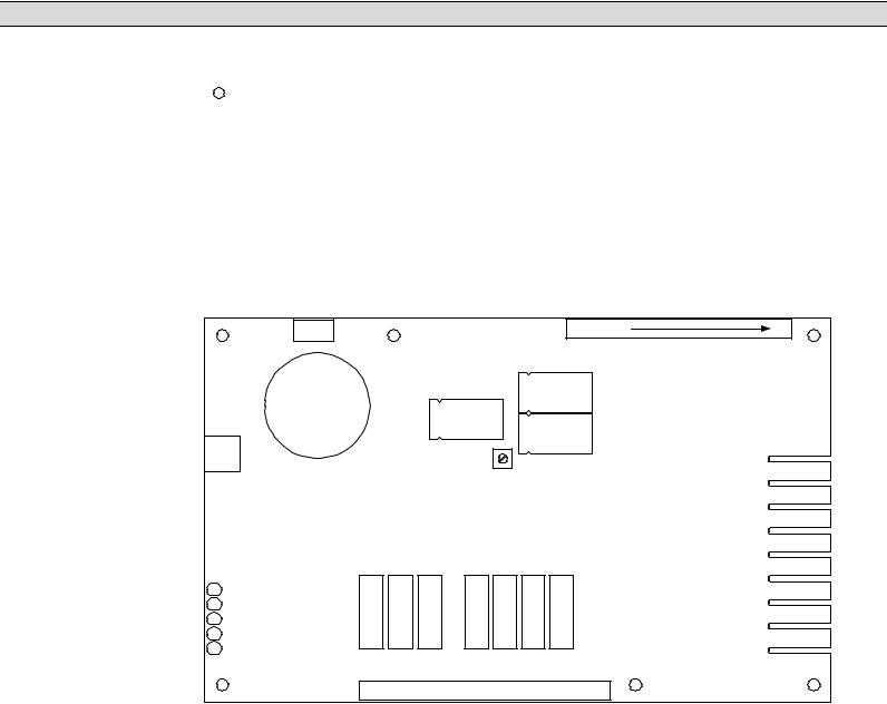
3.2.PRINTED CIRCUIT BOARD
The printed circuit board (PCB) is shown in FIGURE #11. The PCB contains the following user interface items:
MEC 2 CIRCUIT BOARD LAYOUT
B+ B- GRD TB4 |
TB2 MP1 MP2 1 |
17 |
J6 |
|
|
|
R115 |
TB1 |
Expansion |
CONTRAST |
IN |
|
||
Port |
|
IC |
|
|
|
|
|
IB |
|
|
IA |
|
|
VN |
WATCHDOG |
|
VC |
REMOTE START |
|
VB |
CRANK |
|
|
RUN |
|
VA |
COM FAIL |
|
|
|
|
TB3 18  38
38
G:\ENGINEER\PRODUCTS\MEC2MEC2_02.VSD Rev.2 02/01/23
DRAWING SCALE (mm) = .6:1
FIGURE #11
PM056 Rev 6 05/10/15 |
15 |
Thomson Technology |
MEC 2 MICROPROCESSOR ENGINE/GENERATOR CONTROLLER
3.2.1. TERMINAL BLOCKS
Four terminal blocks are located on the PCB as follows:
TB1 AC Voltage and Current sensing terminal block (120-600VAC & 0-5AAC)
|
WARNING!!! |
|
Voltage sensing circuits are capable of lethal voltages while |
|
energized. Current transformer (CT) secondary circuits are capable |
|
of generating lethal voltages when open circuited with their primary |
|
circuit energized. Standard safety procedures should be followed |
|
and be performed by qualified personnel only. Failure to do so may |
|
cause personal injury and/or death. |
TB2 |
Speed sensing and digital contact input terminal block |
TB3 |
Output contacts and engine temperature/pressure input signal terminal |
|
block |
TB4 |
DC power input and ground connection terminal block |
3.2.2. DIAGNOSTIC LED’S
The MEC 2 controller provides five diagnostics LED lights that are mounted on the rear of the printed circuit board as per FIGURE #11. Their functions are described as follows:
3.2.2.1.WATCHDOG
This LED flashes on and off at irregular intervals which indicates that the microprocessor is functioning normally.
3.2.2.2.REMOTE START
This LED is illuminated whenever the MEC 2 has received a remote start signal.
3.2.2.3.CRANK
This LED is illuminated whenever the MEC 2 is initiating an engine cranking signal.
3.2.2.4.RUN
This LED is illuminated whenever the MEC 2 has called the engine to run.
3.2.2.5.COMMON FAIL
This LED is illuminated whenever the MEC 2 has initiated a common fail signal (i.e. whenever an alarm or shutdown fault has been activated).
PM056 Rev 6 05/10/15 |
16 |
Thomson Technology |

MEC 2 MICROPROCESSOR ENGINE/GENERATOR CONTROLLER
Note: All LED’s will be illuminated whenever a lamp test function is performed.
3.2.3. CONTRAST ADJUSTMENT (R115)
A contrast adjustment potentiometer is located on the rear of the PCB and is factory set for ambient temperatures of 15° to 30° Celsius. For different ambient temperatures, consult the factory for adjustment procedures.
4.FAULT CIRCUIT DESCRIPTIONS
The MEC 2 engine-generator controller utilizes many analog and digital inputs to perform both monitoring and control functions. Three types of fault circuits are used to monitor and control the engine-generator set. The first type is Internal Fault Circuits that are derived from a combination of digital and analog inputs. The second type is Digital Input Fault circuits that are initiated from external contact inputs. The third type is Analog Input Fault circuits that are initiated from external analog signal inputs. The following functional block diagram (FIGURE #12) shows how all input/output fault circuits are organized.
PM056 Rev 6 05/10/15 |
17 |
Thomson Technology |

MEC 2 MICROPROCESSOR ENGINE/GENERATOR CONTROLLER
4.1.MEC 2 FUNCTIONAL BLOCK DIAGRAM
|
|
|
FEATURE |
STANDARD FAULTS |
OUTPUT CONTACTS |
|
|
|
MAGNETIC |
|
|
|
|
OVERSPEED |
|
|
|
PICKUP |
|
|
|
|
|
|
|
|
|
|
|
|
SHUTDOWN |
|
|
|
|
|
|
|
|
|
|
|
|
|
|
|
|
RPM |
FAULT |
LOSS OF SPEED |
|
RUN |
|
|
|
|
DISPLAY |
LOGIC |
ALARM/SHUTDOWN |
|
10A, 240Vac, 8A/24Vdc |
|
|
|
|
|
|
OVERCRANK |
|
RESISTIVE |
|
|
|
|
|
|
|
|
|
|
|
|
|
|
|
SHUTDOWN |
|
|
|
|
|
|
AUTO PUSHBUTTON |
|
SWITCH NOT IN AUTO |
|
|
|
|
|
|
|
LOGIC |
|
CRANK |
||
|
|
|
|
|
ALARM |
|
10A, 240Vac, 8A/24Vdc |
|
|
|
|
|
|
LOW ENGINE TEMP. |
|
RESISTIVE |
|
ENGINE TEMPERATURE |
|
|
|
|
|
|||
|
|
ALARM |
|
|
|
|||
SENDER |
|
|
|
|
|
|
|
|
|
|
TEMP. |
FAULT |
HIGH ENGINE TEMP. |
|
|
|
|
|
|
|
|
|
|
|||
|
|
|
DISPLAY |
LOGIC |
ALARM |
|
|
|
|
|
|
|
|
HIGH ENGINE TEMP. |
|
|
|
|
|
|
|
|
SHUTDOWN |
|
|
|
ENGINE OIL PRESSURE |
|
|
LOW OIL PRESSURE |
|
|
|
||
SENDER |
|
|
|
|
|
|
|
|
|
|
PRESS. |
FAULT |
ALARM |
|
|
|
|
|
|
|
|
|
|
|||
|
|
|
|
|
|
|
||
|
|
|
DISPLAY |
LOGIC |
LOW OIL PRESSURE |
|
|
|
|
|
|
|
|
SHUTDOWN |
|
PROGRAMMABLE |
|
|
|
|
|
|
|
|
||
|
|
|
|
|
LOW BATTERY |
2 |
CONTACT #1 |
|
|
|
|
|
|
10A, 240Vac, 8A/24Vdc |
|||
|
|
BATTERY |
|
|
VOLTAGE ALARM |
|
||
– |
+ |
DC |
|
|
RESISTIVE |
|||
VOLTAGE |
FAULT |
HIGH BATTERY |
|
|
|
|||
|
|
|
VOLT |
LOGIC |
VOLTAGE ALARM |
|
|
|
|
|
|
DISPLAY |
|
|
|
||
|
|
|
|
WEAK BATTERY |
|
|
|
|
|
|
|
|
|
|
|
|
|
|
|
|
|
|
ALARM |
|
|
|
|
|
|
|
|
|
|
PROGRAMMABLE |
|
|
3 PHASE AC |
AC |
|
UNDERVOLTAGE |
2 |
CONTACT #2 |
||
|
|
|
10A, 240Vac, 8A/24Vdc |
|||||
|
V |
VOLTAGE |
VOLT/ |
|
SHUTDOWN |
|
RESISTIVE |
|
|
|
FREQ. |
|
UNDERFREQUENCY |
|
|
|
|
|
|
|
DISPLAY |
|
|
|
|
|
|
|
|
|
|
SHUTDOWN |
|
|
|
|
3 PHASE AC |
|
|
|
|
PROGRAMMABLE |
||
|
AC |
|
|
2 |
CONTACT #3 |
|||
|
|
CURRENT |
|
|
||||
|
|
|
|
10A, 240Vac, 8A/24Vdc |
||||
|
|
|
CURRENT |
|
|
|
||
|
|
|
|
|
|
RESISTIVE |
||
|
|
|
DISPLAY |
|
|
|
||
|
|
|
|
|
|
|
|
|
DIGITAL INPUT |
|
|
|
|
|
|
||
CONTACTS (N/O or N/C) |
|
|
|
|
|
|
||
|
1 |
|
|
|
LOW OIL PRESSURE |
|
|
|
|
|
|
|
SHUTDOWN |
|
|
|
|
|
|
|
|
|
|
PROGRAMMABLE |
||
|
|
|
|
|
HIGH ENGINE TEMP. |
|
||
|
2 |
|
|
|
2 |
CONTACT #4 |
||
|
|
|
|
|
SHUTDOWN |
|
10A, 240Vac, 8A/24Vdc |
|
|
3 |
|
|
|
LOW COOLANT |
|
RESISTIVE |
|
|
|
|
|
LEVEL SHUTDOWN |
|
|
|
|
|
|
|
|
|
|
|
|
|
|
4 |
|
|
|
LOW FUEL LEVEL |
|
|
|
|
|
|
|
ALARM |
|
|
|
|
|
|
|
|
|
|
|
|
|
|
|
|
|
FAULT |
|
|
|
|
|
|
|
|
LOGIC |
|
|
NOTES: |
|
|
|
|
|
|
|
|
|
|
|
|
|
|
|
|
|
1 |
DIGITAL FAULT |
|
|
|
|
1 |
|
|
|
LABEL LIST – |
|
|
|
|
|
|
|
|
EACH POINT |
|
|
|
|
|
|
|
|
PROGRAMMABLE |
|
|
|
|
|
|
|
2 |
PROGRAMMABLE |
|
|
|
|
|
|
|
|
FUNCTION LIST |
|
|
|
E. STOP |
|
|
|
|
|
|
|
N/O |
|
|
EMERGENCY STOP |
|
|
|
|
|
|
|
|
|
|
|
|
|
|
|
|
|
|
|
G:\ENGINEER\PRODUCTS\ |
|
|
|
|
|
|
|
|
|
MEC2_05.VSD |
|
|
|
|
|
|
|
|
Rev. 4 02/01/23 |
FIGURE #12
PM056 Rev 6 05/10/15 |
18 |
Thomson Technology |

MEC 2 MICROPROCESSOR ENGINE/GENERATOR CONTROLLER
4.2.INTERNAL FAULT CIRCUITS
The MEC 2 Engine Controller provides four internally activated fault circuits as described below. All internal fault circuits are provided as standard with every MEC 2 controller.
4.2.1. OVER CRANK
The over crank fault circuit is initiated when the engine fails to start after the selected crank time or number of crank cycles. The over crank fault circuit is internally programmed as a latching shutdown fault and is not user programmable. Refer to the programming instructions for further information.
4.2.2. OVER SPEED
The over speed fault circuit is initiated when the engine’s speed has increased above the over speed setpoint. The over speed fault circuit is internally programmed as a latching shutdown fault. The over speed shutdown fault circuit is programmable for the percentage of nominal engine speed (i.e. over speed setpoint) and for the transient time delay period. The programming prompts for over speed are located in the main menu programming loop. Refer to the programming instructions for further information.
4.2.3. LOSS OF SPEED
The loss of speed fault circuit is initiated when the engine’s speed sensing circuit does not detect a speed signal for a period more than 2 seconds following a run signal. The loss of speed fault may be user programmed as a latching shutdown fault or alarm only. The programming prompts for loss of speed are located in the main menu programming loop. Refer to the programming instructions for further information.
4.2.4. SWITCH NOT IN AUTO
The “Switch Not In Auto” fault circuit is initiated when the controller’s operating mode switch is changed from the auto position to any other position via the front mounted keypad. This fault is internally programmed as a non latching alarm. In the main programming loop, this alarm may be user programmed to initiate the common fail output relay.
PM056 Rev 6 05/10/15 |
19 |
Thomson Technology |

MEC 2 MICROPROCESSOR ENGINE/GENERATOR CONTROLLER
4.3.DIGITAL FAULT INPUT CIRCUITS
The MEC 2 Engine Controller provides four digital fault input circuits that are user programmable. Each digital fault input circuit is activated via a remote sensing contact that is external to the controller.
Each digital fault input circuit may be programmed with a unique fault label description as stored in the controller’s non-volatile memory. The following digital fault labels are provided in each MEC 2 Engine Controller:
AIR DAMPER TRIPPED |
HIGH OIL LEVEL |
BAT CHARGER INPUT FAIL |
HIGH OIL TEMP |
BAT CHRG TROUBLE |
HIGH WINDING TEMP |
BREAKER TRIPPED |
LOW COOLANT LEVEL |
DC FAIL |
LOW ENGINE TEMP |
FAILED TO SYNC |
LOW FUEL PRESS |
GEN BREAKER OPEN |
LOW FUEL LEVEL |
GROUND FAULT |
LOW OIL LEVEL |
HIGH BEARING TEMP |
LOW OIL PRESSURE |
HIGH COOLER VIBRATION |
REMOTE EMERG. STOP |
HIGH ENGINE TEMP |
REVERSE POWER |
HIGH ENGINE VIBRATION |
BASIN RUPTURE |
HIGH FUEL LEVEL |
ATS IN BYPASS |
NO LOAD TEST |
FUEL LEAK |
*HIGHINTKMANFTEMP |
LOW FUEL PRESS |
VENT DAMPER FAIL |
BAT CHARGER FAIL |
HIGH FUEL LEVEL |
|
FAIL TO SYNC |
|
“Blank” (i.e. no text for unused inputs) |
|
4.3.1. STANDARD DIGITAL FAULT CIRCUITS
The MEC 2 is supplied from the factory with four standard digital fault circuits as follows:
PM056 Rev 6 05/10/15 |
20 |
Thomson Technology |

MEC 2 MICROPROCESSOR ENGINE/GENERATOR CONTROLLER
FAULT |
FAULT |
INPUT |
NAME |
ACTION |
TERMINAL # |
Low Oil Pressure |
Shutdown |
1 |
High Engine Temperature |
Shutdown |
2 |
Battery Charger Input Fail |
Alarm |
3 |
Low Fuel Level |
Alarm |
4 |
|
|
|
All faults require a customer connected contact to the MEC 2 input terminal as indicated. All fault circuits may be user field programmed for different control functions or alternate fault names.
Note: Shutdown functions for Low Oil Pressure and High Engine Temperature may alternatively be provided via analog pressure and temperature sender inputs if programmed accordingly in the analog fault programming menu. Refer to Section 9.4 for further information.
4.4.ANALOG FAULT INPUT CIRCUITS
The MEC 2 Engine Controller provides up to eight analog fault input circuits that are user programmable. Each analog fault input circuit is activated via specific analog signal type.
WARNING!!!
The analog protection circuits for voltage, frequency, current, engine oil pressure, engine temperature and engine speed will be set at factory default settings only. Final settings will be required to be set by the commissioning authority. Failure to do so may result in severe equipment failure or damage.
4.4.1. ANALOG FAULT CIRCUITS
The MEC 2 is supplied from the factory with fifteen standard analog fault circuits as follows:
PM056 Rev 6 05/10/15 |
21 |
Thomson Technology |

MEC 2 MICROPROCESSOR ENGINE/GENERATOR CONTROLLER
FAULT |
FAULT |
INPUT |
NAME |
ACTION |
SIGNAL |
Over voltage |
Shutdown |
Generator voltage |
Over frequency |
Alarm |
Generator frequency |
Over current |
Alarm |
Generator current |
Under voltage |
Shutdown |
AC Voltage |
Under frequency |
Shutdown |
AC Frequency |
Weak battery |
Alarm |
Battery voltage |
Low battery voltage |
Alarm |
Battery voltage |
High battery voltage |
Alarm |
Battery voltage |
Low engine temperature |
Alarm |
Engine temperature |
High engine temperature #1 |
Alarm |
Engine temperature |
High engine temperature # 2 |
Shutdown |
Engine temperature |
Low oil pressure #1 |
Alarm |
Oil pressure |
Low oil pressure #2 |
Shutdown |
Oil pressure |
Over speed |
Shutdown |
Engine speed |
Loss of speed signal |
Shutdown |
Engine speed |
All fault circuits may be user field programmed for different control functions however their designated fault function is not programmable. Refer to the programming instructions for further information.
4.4.2.GENERATOR AC VOLTAGE
4.4.2.1.GENERATOR UNDER VOLTAGE
The MEC 2 controller provides a 3-phase under voltage sensor for the generator supply. The under voltage sensor is programmable for type of fault action (i.e. alarm or shutdown), pickup and dropout voltage setpoints (i.e. adjustable hysteresis) and transient time delay settings. Refer to the programming instructions for further information.
4.4.2.2.GENERATOR OVER VOLTAGE
The MEC 2 controller provides a 3-phase over voltage sensor for the generator supply. The over voltage sensor is programmable for type of fault action (i.e. alarm or shutdown), pickup and dropout voltage setpoints
PM056 Rev 6 05/10/15 |
22 |
Thomson Technology |
 Loading...