


 Loading...
Sony HKDV-506A, BKDW-509, 507D, HKDV-503, HKDV-501A User Manual
...HD DIGITAL VIDEOCASSETTE RECORDER
HDW-F500
PARALLEL INTERFACE KIT
BKDW-509
HD-SD CONVERTER BOARD
HKDV-501A
HD LINE CONVERTER BOARD
HKDV-502
HD DIGITAL VIDEO CONTROLLER
HKDV-503
SDTI BOARD
HKDV-506A
HD PULL DOWN BOARD
HKDV-507/507D
OPERATION MANUAL [ English ] 1st Edition (Revised 3)
Serial No. 10101 and Higher

WARNING
To prevent fire or shock hazard, do not expose the unit to rain or moisture.
To avoid electrical shock, do not open the cabinet. Refer servicing to qualified personnel only.
THIS APPARATUS MUST BE EARTHED.
This symbol is intended to alert the user to the presence of important operating and maintenance (servicing) instructions in the literature accompanying the appliance.
WARNING: THIS WARNING IS APPLICABLE FOR USA ONLY.
If used in USA, use the UL LISTED power cord specified below.
DO NOT USE ANY OTHER POWER CORD.
Plug Cap |
Parallel Blade with ground pin |
|
(NEMA 5-15P Configuration) |
Cord |
Type SJT, three 16 or 18 AWG |
|
wires |
Length |
Less than 2.5m(8 ft 3 in) |
Rating |
Minimum 10 A, 125 V |
Using this unit at a voltage other than 120V may require the use of a different line cord or attachment plug, or both. To reduce the risk of fire or electric shock, refer servicing to qualified service personnel.
For the customers in U.S.A.
This equipment has been tested and found to comply with the limits for a Class A digital device, pursuant to Part 15 of the FCC Rules. These limits are designed to provide reasonable protection against harmful interference when the equipment is operated in a commercial environment. This equipment generates, uses, and can radiate radio frequency energy and, if not installed and used in accordance with the instruction manual, may cause harmful interference to radio communications. Operation of this equipment in a residential area is likely to cause harmful interference in which case the user will be required to correct the interference at his own expense.
You are cautioned that any changes or modifications not expressly approved in this manual could void your authority to operate this equipment.
The shielded interface cable recommended in this manual must be used with this equipment in order to comply with the limits for a digital device pursuant to Subpart B of Part 15 of FCC Rules.
For the customers in Europe
This product with the CE marking complies with both the EMC Directive (89/336/EEC) and the Low Voltage Directive (73/23/EEC) issued by the Commission of the European Community.
Compliance with these directives implies conformity to the following European standards:
•EN60065: Product Safety
•EN55103-1: Electromagnetic Interference (Emission)
•EN55103-2: Electromagnetic Susceptibility (Immunity) This product is intended for use in the following Electromagnetic Environment:E4 (Controlled EMC environment ex. TV studio).
AVERTISSEMENT
Afin d’éviter tout risque d’incendie ou d’électrocution, ne pas exposer cet appareil à la pluie ou à l’humidité.
Afin d’écarter tour risque d’électrocution, garder le coffret fermé. Ne confier l’entretien de l’appareil qu’à un personnel qualifié.
CET APPAREIL DOIT ÉTRE RELIÉ Á LA TERRE.
Pour les clients européens
Ce produit portant la marque CE est conforme à la fois à la Directive sur la compatibilité électromagnétique (EMC) (89/ 336/CEE) et à la Directive sur les basses tensions (73/23/ CEE) émises par la Commission de la Communauté européenne.
La conformité à ces directives implique la conformité aux normes européennes suivantes:
•EN60065: Sécurité des produits
•EN55103-1: Interférences électromagnétiques (émission)
•EN55103-2: Sensibilité électromagnétique (immunité)
Ce produit est prévu pour être utilisé dans l'environnement électromagnétique suivant:
E4 (environnement EMC contrôlé ex. studio de télévision).

VORSICHT
Um Feuergefahr und die Gefahr eines elektrischen Schlages zu vermeiden, darf das Gerät weder Regen noch Feuchtigkeit ausgesetzt werden.
Um einen elektrischen Schlag zu vermeiden, darf das Gehäuse nicht geöffnet werden. Überlassen Sie Wartungsarbeiten stets nur qualifiziertem Fachpersonal.
DIESES GERÄT MUSS GEERDET WERDEN.
Für Kunden in Europa
Dieses Produkt besitzt die CE-Kennzeichnung und erfüllt sowohl die EMV-Direktive (89/336/EEC) als auch die Directive Niederspannung (73/23/EEC) der EGKommission.
Die Erfüllung dieser Direktiven bedeutet Konformität für die folgenden Europäischen Normen:
•EN60065: Produktsicherheit
•EN55103-1: Elektromagnetische Interferenz (Emission)
•EN55103-2: Elektromagnetische Empfindlichkeit (Immunität)
Dieses Produkt ist für den Einsatz unter die folgende elektromagnetische Bedingung ausgelegt:
E4 (kontrollierter EMV-Bereich, z.B. Fernsehstudio).

Table of Contents
Chapter 1
Overview
Chapter 2
Locations and Functions
of Parts and Controls
Chapter 3
Setting Up the VTR
Chapter 4
Menu Settings
(Continued)
|
............................................................................................1-1 Features |
1-1 |
|
1-1-1 Features of the HDW-F500 .................................................... |
1-1 |
|
1-1-2 Features of the Control Panel ................................................. |
1-3 |
|
1-2 Optional Accessories ....................................................................... |
1-5 |
|
2-1 Control Panel ................................................................................... |
2-1 |
|
2-1-1 Upper Control Panel ............................................................... |
2-2 |
|
2-1-2 Lower Control Panel (Menu Operations Section) .................. |
2-5 |
|
2-1-3 Lower Control Panel (Editing Operations Section) ................ |
2-7 |
|
2-1-4 Lower Control Panel (Tape Transport Operations Section) ... |
2-9 |
|
2-1-5 Lower Control Panel (Search Operations Section) ............... |
2-11 |
|
2-2 System Set-Up Panel ..................................................................... |
2-13 |
|
2-3 Connector Panel ............................................................................ |
2-14 |
|
3-1 Connecting External Equipment ................................................... |
3-1 |
|
3-1-1 Making Digital Connections ................................................... |
3-1 |
|
3-1-2 Making HD Analog Connections ........................................... |
3-2 |
|
3-1-3 Making NTSC/PAL Digital Connections ............................... |
3-3 |
|
3-1-4 Cascade connection ................................................................ |
3-4 |
|
3-2 Reference Signals for Video Output and Servo System............... |
3-5 |
|
3-2-1 Reference Signals for Output Video ....................................... |
3-5 |
|
3-2-2 Reference Signals Connections .............................................. |
3-6 |
|
3-3 Handling Cassettes .......................................................................... |
3-8 |
|
3-3-1 Recommended Cassettes ........................................................ |
3-8 |
|
3-3-2 Inserting and Ejecting Cassettes ............................................. |
3-8 |
|
3-3-3 Preventing Accidental Erasure ............................................... |
3-9 |
|
4-1 Registering and Storing Menu Settings ......................................... |
4-1 |
|
4-1-1 Menu Configuration ............................................................... |
4-1 |
|
4-1-2 Changing Menu Settings ........................................................ |
4-2 |
|
4-1-3 Registering Items to the PF1/2 Menus ................................... |
4-3 |
|
4-1-4 VTR Memory Bank Function ................................................. |
4-4 |
|
4-1-5 Memory Card Function .......................................................... |
4-6 |
|
4-1-6 Adding Titles to the Data ...................................................... |
4-11 |
|
4-1-7 Details on VTR Memory Bank and Memory Card Functions 4-12 |
|
|
4-1-8 Memory Card Data Compatibility ........................................ |
4-13 |
|
4-2 HOME Menu ................................................................................. |
4-14 |
|
4-2-1 Selecting the Output Signals(PB/EE) ................................... |
4-16 |
|
4-2-2 Record Inhibit Mode (REC INH) ......................................... |
4-16 |
|
4-2-3 Selecting the Edit Mode and Edit Channel |
|
|
(ASSEMBLE or INS CUE) ................................................ |
4-17 |
|
4-2-4 Preread Settings (PRE READ) ............................................. |
4-17 |
|
4-2-5 Still-Picture Output (FREEZE) ............................................ |
4-17 |
|
4-2-6 Selecting the Capstan Servo Lock Mode (CAP LOCK) ...... |
4-18 |
|
4-2-7 Setting the Preroll Time (PREROLL TIME) ....................... |
4-18 |
|
4-2-8 Selecting DMC Playback (DMC) ......................................... |
4-19 |
|
4-2-9 Recalling Edit Points (LAST EDIT) .................................... |
4-19 |
|
|
|
Contents of Table
|
Table of Contents |
1 |
|

Contents of Table
Table of Contents
Chapter 4
Menu Settings
|
|
........................................................................................4-3 TC Menu |
4-20 |
|
|
|
|
4-3-1 Setting the Time Data (TIMER SEL/RESET/SET/HOLD) 4-21 |
|
|
|
|
4-3-2 Setting the Time Code Reader (TCR SEL) .......................... |
4-24 |
|
|
|
4-3-3 Setting the Time Code Generator (TCG SOURCE/MODE) 4-25 |
|
|
|
|
4-3-4 Selecting the Time Code Running Mode (RUN MODE) ..... |
4-25 |
|
|
|
4-3-5 Selecting the Drop Frame Mode (DF/NDF) ......................... |
4-25 |
|
|
|
4-3-6 Inserting VITC input source (VITC) .................................... |
4-26 |
|
|
|
4-3-7 Selecting CTL Display Mode (TAPE TIMER) .................... |
4-26 |
|
|
|
4-3-8 Presetting Pull Down Time Code (PDPSET MENU) |
|
|
|
|
(when HKDV-507/507D is installed) .................................. |
4-26 |
|
|
|
4-3-9 Presetting for Conversion From 24-frame Into 25-frame Time |
|
|
|
|
Code (TCCONV MENU) .................................................... |
4-27 |
|
|
|
4-3-10 Conversion of Time Code During Playback in 25F Mode |
|
|
|
|
(TC CONV) .......................................................................... |
4-29 |
|
|
|
4-3-11 Displaying the Pull Down Time Code |
|
|
|
|
(when HKDV-507/507D is installed) ................................ |
4-29 |
|
|
|
4-3-12 Superimposition of Character Information |
|
|
|
|
(PD CHARA/CHARA SUPER/H-POS/V-POS) ................. |
4-30 |
|
|
|
4-3-13 Setting the VITC Insertion Line (VITC POS-1/POS-2) ..... |
4-32 |
|
|
|
4-3-14 Presetting for Conversion From 25-frame Into 24-frame Time |
|
|
|
|
Code (TCCONV MENU) .................................................... |
4-33 |
|
|
|
4-3-15 Conversion of Time Code During Playback in 24F Mode |
|
|
|
|
(TC CONV) .......................................................................... |
4-34 |
|
|
4-4 CUE Menu ..................................................................................... |
4-35 |
|
|
|
|
4-4-1 Selecting a Multi-Cue Mode ................................................. |
4-36 |
|
|
|
4-4-2 Registering Cue Points ......................................................... |
4-36 |
|
|
|
4-4-3 Erasing Cue Point Data ......................................................... |
4-38 |
|
|
|
4-4-4 Prerolling to a Cue Point ...................................................... |
4-39 |
|
|
|
4-4-5 Changing a Cue Point Into an Edit Point .............................. |
4-40 |
|
|
|
4-4-6 Backspace Editing ................................................................ |
4-40 |
|
|
|
4-4-7 TELE FILE Menu ................................................................. |
4-41 |
|
|
4-5 PF1 Menu (Factory Settings) ....................................................... |
4-55 |
|
|
|
|
4-5-1 Selecting the Input Video Signal (VIDEO IN) ..................... |
4-56 |
|
|
|
4-5-2 Selecting the Reference Signal (SERVO REF) .................... |
4-56 |
|
|
|
4-5-3 Adjusting the Output Video Signal |
|
|
|
|
(MASTER LEVEL to FINE) ............................................... |
4-56 |
|
|
4-6 PF2 Menu (Factory Settings) ....................................................... |
4-59 |
|
|
|
|
4-6-1 Selecting the Audio Input Signal (A-IN CH-1~CH4) .......... |
4-60 |
|
|
|
4-6-2 Setting Emphasis (EMPHASIS) ........................................... |
4-60 |
|
|
|
4-6-3 Selecting the Monitor Output Signal |
|
|
|
|
(MON-L SEL/MON-R SEL) ............................................... |
4-60 |
|
|
4-7 SET UP Menu ................................................................................ |
4-61 |
|
|
|
|
4-7-1 VTR SETUP Menu ............................................................... |
4-63 |
|
|
|
4-7-2 PANEL SETUP Menu .......................................................... |
4-65 |
|
|
|
|
|
2 Table of Contents

Chapter 5
Recording/Playback
Chapter 6
Editing
|
|
.................................................................5-1 Preparing for Recording |
5-1 |
|
|
|
|
5-1-1 Setting Switches and Menus ................................................... |
5-1 |
|
|
|
5-1-2 Selecting Audio Signals .......................................................... |
5-2 |
|
|
|
5-1-3 Adjusting the Audio Recording Level .................................... |
5-3 |
|
|
|
5-1-4 Simultaneously Monitoring Playback of Video and Audio |
|
|
|
|
Signals Being Recorded ......................................................... |
5-4 |
|
|
|
5-1-5 Recording Analog Audio ........................................................ |
5-4 |
|
|
5-2 Recording ......................................................................................... |
5-5 |
|
|
|
5-3 Preparing for Playback ................................................................... |
5-6 |
|
|
|
|
5-3-1 Setting Switches and Menus ................................................... |
5-6 |
|
|
|
5-3-2 Adjusting the Audio Playback Level ...................................... |
5-6 |
|
|
|
5-3-3 Selecting the HD-SD Conversion Mode |
|
|
|
|
(when HKDV-501A is installed) ........................................... |
5-7 |
|
|
|
5-3-4 Selecting the Conversion Mode of the Effective Scanning Line |
|
|
|
|
Number (when HKDV-502 is installed) ................................ |
5-8 |
|
|
|
5-3-5 Improving the Vertical Resolution during Slow-Motion |
|
|
|
|
Playback (when HKDV-502 is installed) ............................... |
5-9 |
|
|
5-4 Playback ......................................................................................... |
5-11 |
|
|
|
|
5-4-1 Normal-Speed Playback ....................................................... |
5-11 |
|
|
|
5-4-2 Variable Speed Playback ...................................................... |
5-11 |
|
|
|
5-4-3 Capstan Override Playback .................................................. |
5-14 |
|
|
|
5-4-4 DMC Playback ..................................................................... |
5-14 |
|
|
|
5-4-5 Playing Back Non-audio Data .............................................. |
5-16 |
|
|
|
5-4-6 Output of Pull Down Signal ................................................. |
5-16 |
|
|
6-1 Basic Automatic Editing ................................................................. |
6-1 |
|
|
|
|
6-1-1 Overview of Automatic Editing ............................................. |
6-1 |
|
|
|
6-1-2 Setting Switches and Menus ................................................... |
6-2 |
|
|
|
6-1-3 Selecting the Edit Mode ......................................................... |
6-3 |
|
|
|
6-1-4 Setting Edit Points .................................................................. |
6-3 |
|
|
|
6-1-5 Editing Non-audio Data .......................................................... |
6-7 |
|
|
|
6-1-6 Confirming Edit Points ........................................................... |
6-8 |
|
|
|
6-1-7 Cuing Up and Prerolling ......................................................... |
6-8 |
|
|
|
6-1-8 Previewing .............................................................................. |
6-9 |
|
|
|
6-1-9 Modifying Edit Points .......................................................... |
6-10 |
|
|
|
6-1-10 Performing Automatic Editing ........................................... |
6-12 |
|
|
6-2 Advanced Automatic Editing ....................................................... |
6-15 |
|
|
|
|
6-2-1 Performing DMC Editing ..................................................... |
6-15 |
|
|
|
6-2-2 Animation Editing ................................................................ |
6-17 |
|
|
|
6-2-3 Performing Preread Editing .................................................. |
6-18 |
|
|
6-3 Manual Editing .............................................................................. |
6-19 |
|
|
|
|
|
|
|
|
|
|
|
Contents of Table
Table of Contents |
3 |

Contents of Table
Table of Contents
Appendix
|
|
..........................................................................................Maintenance |
A-1 |
|
|
|
|
Head Cleaning ................................................................................. |
A-1 |
|
|
|
Moisture Condensation ................................................................... |
A-1 |
|
|
Specifications ......................................................................................... |
A-2 |
|
|
|
Operation Information Display ........................................................... |
A-6 |
|
|
|
Error Messages and Warning Messages ............................................ |
A-8 |
|
|
|
|
Error Messages ................................................................................ |
A-8 |
|
|
|
Warning Messages ........................................................................ |
A-10 |
|
|
|
Error Log Menu ............................................................................. |
A-11 |
|
|
Glossary ............................................................................................... |
A-13 |
|
|
|
Menu List ............................................................................................ |
A-15 |
|
|
|
|
Items Related to the Hours Meter (H01~) ..................................... |
A-15 |
|
|
|
Items Related to VTR Operations (001~) ..................................... |
A-16 |
|
|
|
Items Related to Operation Panels (101~) .................................... |
A-20 |
|
|
|
Items Related to Remote Interface (201~) .................................... |
A-23 |
|
|
|
Items Related to Editing (301~) .................................................... |
A-24 |
|
|
|
Items Related to Prerolling (401~) ................................................ |
A-27 |
|
|
|
Items Related to Recording Protection (501~) .............................. |
A-28 |
|
|
|
Items Related to the Time Code (601~) ........................................ |
A-29 |
|
|
|
Items Related to the Video Control (701~) ................................... |
A-34 |
|
|
|
Items Related to the Audio Control (801~) ................................... |
A-39 |
|
|
|
Items Related to Digital Processing (901~) .................................. |
A-42 |
|
|
|
Items Related to the Pull Down Control (A01~) ........................... |
A-44 |
|
|
|
Other Items (T01~) ........................................................................ |
A-46 |
|
|
Index ........................................................................................................ |
I-1 |
|
|
|
Table of Functions (Factory Default Settings) ......................... |
Last page |
|
|
|
|
|
|
4 Table of Contents

1-1 Features
1-1-1 Features of the HDW-F500
The HDW-F500 is a HD digital videocassette recorder using the HDCAM1) format. Comparable to a conventional digital Betacam in size, weight, and ease- of-use, the HDW-F500 is a small, lightweight HD digital VTR using integrated circuit technology.
HDCAM Format
The HDCAM format was developed from the digital Betacam format, and retains the same ease of use of digital Betacam, while yielding high performance HD digital recording and playback. The HDCAM format uses the following technologies:
•Pre-filtering and a new coefficient recording system, compressing the data by a factor of seven.
•Powerful error-correcting codes
•High-performance, high-accuracy heads and drum with dynamic tracking (DT)™, together with a new auto-tracking technique, yielding highly reliable narrow track recording and playback.
Together, these technologies allow 120 minutes of recording on a (large size) 1/2-inch HDCAM cassette, the same size as a conventional digital Betacam cassette.
Digital Signal Processing
In an HDCAM VTR, the signal processing takes a 4:2:2 component signal which has been quantized according to ITU-R709/SMPTE 274M/SMPTE 260M(BTA S-002B) standards, and subjects it to prefilter, and then further applies data compression by using a coefficient recording system. Audio signals are processed using full bit processing based on the AES/EBU format.
Input interface
The input interface is based on the SMPTE 291M/ 292M/299M(BTA S-004B/-005B/-006B) /ARIB STD B-4 HD component SDI(Serial Digital Interface) format, allowing a single BNC coaxial cable to carry one component video signal, four digital audio channels, and time code in time division multiplex; this is separated for conversion to parallel data.
The interface can be used to record audio data from an AES/EBU digital interface or digitally converted analog signals.
Bit rate reduction encoder
The component video signal data is compressed by a factor of about four by a process in which it is subjected to frame shuffling, blocking, DCT (discrete cosine transform), quantizing adjustment, and variable length word encoding. This is the core of the newly developed coefficient recording system.
ECC encoder
The outer ECC (Error Correction Code) is added to the compressed video and audio data, followed by the inner ECC, ID data, and sync data. The ReedSolomon code is employed in this error correction system.
Channel coding
Video and audio data with the ECC added is recorded in the form of serial data. The HDCAM format adopts a scrambled NRZI channel coding system for off-track and noise characteristics.
Playback signal processing
The playback digital data is equalized by equalizer circuits and error-corrected by powerful inner and outer ECC, which can correct most data disturbed by noise and dropouts in the reproduced signal. Data that cannot be completely corrected in this way is passed through a bit reduction decoder and corrected by an error concealment circuit.
Output interface
Component video data are converted into serial data and multiplexed with audio data and time code, then output in the HD SDI format.
By installing an HD-SD Converter Board (HKDV501A; optional accessory), D1 SDI or D2 SDI and analog composite outputs are also available.
Audio output can be data from the AES/EBU digital interface or analog audio converted from digital signals.
..........................................................................................................................................................................................................
1) HDCAM is a trademark of Sony Corporation.
1 Chapter
OverChapter1 Oveview view
Chapter 1 Overview 1-1

Overview 1 Chapter
1-1 Features
Advanced Recording and Playback
Functions
High-quality digital recording
The HDCAM system uses a component system to record video signals. An AES/EBU format with a wide dynamic range is used for 4-channel audio recording. A unique and powerful error correction circuit and concealment circuit are used in digital signal processing.
Accurate, stable video signal output is made possible by setting and adjusting an internal digital video processor.
8 kinds of record/playback modes
As the record/playback mode, you can select from the following 8 modes. 59.94i/60i/50i/23.98PsF/24PsF/25PsF/29.97PsF/30PsF
HD pull down
By installing an optional HD Pull Down Board HKDV-507/507D, the HD SDI output (to which the audio signal and VITC are multiplexed) of 59.94i or 60i mode are also available when the unit is operated in the 23.98PsF or 24PsF mode.
Noiseless playback with DT heads
Using the playback DT heads, you can perform noiseless playback at 51 speeds ranging from –1 to +2 times normal speed, including still-picture playback.
Video and audio confidence heads
Video and audio (channels 1 through 4) signals can be recorded and simultaneously played back to check the recording.
Internal time code generator and reader
The internal time code generator allows you to record time code (LTC or user bits) together with video and audio signals. Time codes (LTC or user bits) can be read during playback using the time code reader.
Computer servo system
Computer-controlled servo motors provide direct drive for the drum, capstan, and two reels, enabling quick and accurate tape access.
Capstan override function
You can adjust the playback speed by ±15% to ensure synchronization between, for example, two VTRs playing back the same program.
Independent level controls
The recording and playback levels of each of the four audio channels can be adjusted independently while peak values on all four audio channels are monitored.
Tele-File1) memory label system
The HDW-F500 incorporates the Tele-File memory label system to allow users to write and update videocassette management information and cue point data on optional MLB-1B-100 memory labels, providing greater efficiency in cassette management and editing.
Features for Ease of Operation
Compact, lightweight, low power consumption
The VTR is small and light enough to be used in outside broadcast vans or in EFP (Electronic Field Production) assignments.
Remote control operation
The VTR has a serial RS-422A 9-pin connector to allow control of the VTR by an external control unit through RS-422A communications.
The VTR also comes with 9-pin REMOTE1-IN(9P) and OUT(9P) connectors to support bridge connection of multiple HDW-F500 units or other VTRs equipped with 9-pin remote connectors for simultaneous operation. Furthermore, by using the optional BKDW-509 Parallel (50-pin) Interface Kit, you can control the VTR from an external control unit with a parallel interface.
Digital hours meter
Three different hour displays and one cycle count display are supported, showing total elapsed time since the VTR was turned on, total drum revolution time, total tape running time and total number of threadings and unthreadings.
..........................................................................................................................................................................................................
1)A contact-free system for writing, reading, and modifying video cassette-related information on IC memory-bearing labels. Tele-File is a trademark of Sony Corporation.
1-2 Chapter 1 Overview
Self-diagnosis
This function allows the VTR to perform self diagnostics when a malfunction occurs. An error message is displayed and a history of all errors that have occurred is recorded.
Easy-to-maintain plug-in boards
The VTR uses plug-in circuit boards to simplify servicing and inspection.
Mountable in standard 19-inch rack
The unit can be mounted in an EIA-standard 19-inch rack.
For rack mounting, refer to the Maintenance Manual.
1-1-2 Features of the Control
Panel
The BKDW-515 Control Panel provides six menu screens corresponding to the six operation modes to allow fast and easy adjustment of necessary settings, as well as the ability to store menu settings to a memory card for later recall.
Menu-driven operations for a variety of purposes
Six menus are displayed on the 90 × 72 mm (3 5/8 inches × 2 7/8 inches) screen and are set using the 10 function keys.
HOME menu
Use this menu to make the basic settings for recording, playback, and editing operations, and to select channels to be edited during insert editing.
TC menu
Use this menu to make time code settings.
CUE menu
Use this menu to set up to 100 cue points. In page mode, 10 cue points per page can be set on a total of 10 pages. In TELE FILE menu, you can change the setting for the memory label system Tele-File.
PF1/PF2 (Personal Function) menus
Use these menus to register up to 40 of the most frequently used items from the other menus (up to ten items each can be registered to PF1, ALT+ PF1, PF2 and ALT+PF2). Menu items that may be registered can be displayed by pressing the [F4] (PF1&2 ASSIGN) button in the SET UP menu.
SET UP menu
•The VTR BANK menu allows up to eight pages of menu settings to be saved.
•Use the MEMORY CARD menu to store current settings of the VTR and up to 8 pages of the contents of the VTR memory bank to a memory card.
•Use the scrollable PF1&2 ASSIGN menu to display the items that can be registered in the PF1/PF2 menus, and to select and register the most frequently used menu items.
•Use the scrollable VTR SETUP menu to display the items necessary for making initial settings, and to directly change settings without registering them with the function buttons for each menu.
•Use the PANEL SETUP menu to set control panel operations, such as the keyboard sound output.
MAINTENANCE menu
Use this menu to access the maintenance functions.
For details, refer to the Maintenance Manual.
A full complement of storage/recall functions
These functions allow you to use titles to store and recall menu settings in either the VTR’s internal memory banks or memory cards.
VTR memory banks
These memory banks allow you to store up to eight pages of VTR settings in addition to the current VTR settings. Factory settings are also stored here, allowing the VTR to be reset to these values at any time.
Memory cards
Each memory card can hold the current VTR settings as well as up to eight pages of settings. A single memory card thus allows you to store and recall the entire contents of the VTR memory banks.
Overview 1 Chapter
Chapter 1 Overview 1-3

Overview 1 Chapter
1-1 Features
Title function
This function allows you to add titles when storing data to the VTR memory bank or memory card, thus facilitating data retrieval and management.
Write protect function
Setting pages stored in VTR memory banks or memory cards can be write protected on an individual basis.
A full range of editing functions
Two HDW-F500 units can be connected allowing automatic or manual assembly and insertion. The VTR also features a full range of editing functions, including preview, review, preroll, and the setting or changing of edit points.
Quick access to edit points
The following methods are provided for the setting of edit points:
•Multi-cuing for up to 100 edit points
•Search dial with shuttle and jog functions
•Direct input through numeric buttons
DMC (Dynamic Motion Control) editing
Using the DT® (Dynamic Tracking) heads, you can play back a section of an edit at speeds between –1 and +2 times normal speed and store the speed variation in memory for later use in automatic editing.
Split editing
In insert mode, audio and video edit points can be set separately.
Preread editing
Video and audio signals that have been pre-read can be externally processed and simultaneously re-recorded.
A variety of audio editing modes
You can select cut-in editing, cross-fade editing, and fade in/out editing for the audio signals.
Display of duration between edit points
The duration between any two of IN, OUT, AUDIO IN, or AUDIO OUT points can be displayed by simultaneously pressing two buttons corresponding to those edit points.
Digital time counter
The time counter display shows CTL and time codes (LTC/VITC1)), or user bits data for precise setting of edit points.
..........................................................................................................................................................................................................
1)LTC (Longitudinal Time Code)
Time code recorded on a longitudinal track
VITC (Vertical Interval Time Code)
Time code recorded on a video track during the vertical blanking interval
1-4 Chapter 1 Overview

1-2 Optional Accessories
The following accessories can be used with the HDWF500.
BKDW-509 Parallel (50-pin) Interface Kit
A 50-pin parallel interfaces makes the HDW-F500 compatible with different broadcast station systems.
HKDV-501A HD-SD Converter Board
Allows you to output an NTSC/PAL component or composite signal.
HKDV-502 HD Line Converter Board
•Allows you to convert an effective scanning line number from 1035 to 1080 or from 1080 to 1035.
Note
This function is operative only when the frame frequency of the VTR is set to 29.97Hz or 30Hz.
•Allows you to smooth the picture motion and improve the vertical resolution during slow-motion playback. Note that this function does not work when this VTR is operated in PsF mode.
HKDV-503 HD Digital Video Controller
This allows you to remotely control the parameters for video signals and image enhancement.
HKDV-506A SDTI Board
This board allows the input and output of special nondegrading SDTI1) (270Mbps) signals.
HKDV-507/507D HD Pull Down Board
This board allows the output of 2-3 pull down HD signal of 59.94i or 60i mode when this unit is operated with the frame frequency of 23.98 or 24 Hz. The 2-3 pull down sequence is as follows.
A(f1) A(f2) B(f1) B(f2) C(f1) C(f2) D(f1) D(f2)
A(f1) A(f2) B(f1) B(f2) B(f1) C(f2) C(f1) D(f2) D(f1) D(f2)
Note
The 2-3 pull down sequence is guaranteed only when this VTR is in normal play mode.
References
In addition to this Operation Manual, the following manuals are available:
•Maintenance Manual Part 1
Provides information necessary for users to maintain the VTR.
•Maintenance Manual Part 2 (sold separately) Provides additional information to fully maintain the HDW-F500. Contains details on electrical adjustments, circuit diagrams, and other items.
Overview 1 Chapter
..........................................................................................................................................................................................................
1)SDTI (Serial Data Transport Interface)
SDTI is defined as SMPTE-305M.
Chapter 1 Overview 1-5
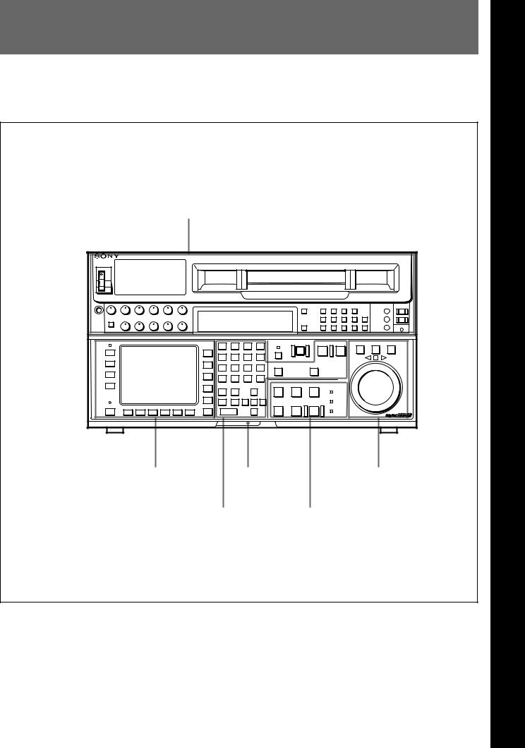
2-1 Control Panel
|
|
The control panel consists of the following sections: |
memory card insertion slot, editing operations |
• Upper control panel |
section, tape transport operations section and search |
• Lower control panel: menu operations section, |
operations section |
Upper control panel
DIGITALVIDEO CASSETTE RECORDER HDW-F500 
Lower control panel
Menu operations section |
Memory card |
Search operations section |
|
insertion slot |
|
Editing operations section |
Tape transport operations section |
|
Control panel
2 Chapter
LocationsChapter
2
andLoctionsand FunctionsFofnctions Partsand
ofPControls artsand
Controls
Chapter 2 Locations and Functions of Parts and Controls |
2-1 |

Controls and Parts of Functions and Locations 2 Chapter
2-1 Control Panel
2-1-1 Upper Control Panel
1DISPLAY FULL/FINE button
2PHONES jack
3POWER switch
4PHONES level control
5 PB level 6REC level controls 7Audio level meters 8MONITOR SELECT button controls
DIGITALVIDEO CASSETTE RECORDER HDW-F500 |
9Indicator window
!ºINPUT SELECT button
!¡AUDIO INPUT/MONITOR SELECT buttons
!™REFERENCE signal indicators
!£REMOTE buttons and RS-232C indicator
Upper control panel
1 DISPLAY FULL/FINE button
Changes the display range of the audio level meters. FULL: Display range is –60 to 0 dB (peak level = 0
dB) or –40 to +20 dB (peak level = +20 dB). Use 814. LEVEL METER SCALE in the VTR SETUP menu to select the range.
FINE: Displays the audio level in 0.25 dB increments. The center LED lights up in each meter as a signal level reference. When the level exceeds the maximum display value, the top LED flashes. When the level falls below the minimum display value, the bottom LED flashes.
2 PHONES jack
Connects stereo headphones with 8 Ω impedance for audio monitoring during recording, playback, and editing. Adjust the headphone output level with the PHONES level control.
3 POWER switch
Turns on the power. When the power is turned on, the audio level meters and menu display in the lower control panel light up.
2-2 |
Chapter 2 Locations and Functions of Parts and Controls |

4 PHONES level control
Adjusts the output level to the PHONES jack.
You can enable this control to simultaneously adjust the output level to the MONITOR OUTPUT connectors on the connector panel.
For details, see Section 5-1-2, “Selecting Audio Signals” on page 5-2.
5 PB (playback) level controls
Adjust the level of the audio output for channels 1 to 4 and the cue channel.
Pull out the controls during playback to adjust the audio output for each channel. Push in again for factory-set levels (+4 dB output for a signal recorded at a reference level of 0 dB). When pushed in, the controls cannot adjust the audio output level.
6 REC (recording) level controls
Adjust the recording level for channels 1 to 4 and the cue channel.
Pull out the controls to adjust the recording level for each channel in E-E mode1). Push in again for the factory-set recording level (0 dB reference level for an input of +4 dB). When pushed in, the controls cannot adjust the recording level.
7 Audio level meters
Indicate the recording level in recording or E-E mode or the playback level in playback or CONFI mode. The display range can be changed by pressing the DISPLAY FULL/FINE button. The reference level is factory set at –20 dB, and the peak level at 0 dB.
8 MONITOR SELECT button
Selects the audio signal to be output at the MONITOR OUTPUT L/R connector(s). Press to light the button up, then press the AUDIO INPUT/MONITOR SELECT button(s) to specify which channel(s) are to be monitored at the MONITOR OUTPUT L or R connector. If you specify more than one channel to the same MONITOR OUTPUT connector, a mixed audio signal is output from that connector. This specification can also be done with setting the VTR SETUP menu 807~808 AUDIO MONITOR L~R select .
9 Indicator window
The following indicators light up to indicate the VTR’s status.
Indicators and corresponding VTR status
Indicator |
Status |
CHANNEL |
Indicates the playback signal condition. |
CONDITION |
Green: Playback signal is good. |
|
Yellow: Playback signal is less than |
|
good, but still reproducible. |
|
Red: Playback signal is poor. Head |
|
cleaning or internal inspection is |
|
necessary if the indicator lights up |
|
continuously. |
INTERLACE |
Lights when the VTR is operating under |
|
the interlace mode(50i/59.94i/60i). |
|
|
PsF |
Lights when the VTR is operating under |
|
the PsF mode(23.98PsF/24PsF/25PsF/ |
|
29.97PsF/30PsF). |
|
|
23.98 |
Lights when the VTR is operating with a |
|
frame frequency of 23.98 Hz. |
24 |
Lights when the VTR is operating with a |
|
frame frequency of 24 Hz. |
|
|
25 |
Lights when the VTR is operating with a |
|
frame frequency of 25 Hz. |
29.97 |
Lights when the VTR is operating with a |
|
frame frequency of 29.97 Hz. |
|
|
30 |
Lights when the VTR is operating with a |
|
frame frequency of 30 Hz. |
|
|
ADV. AUDIO |
Lights when item 821.AUDIO ADVANCE |
|
MODE in the VTR SETUP menu is set to |
|
“on.” When edit preset is set to “ON”, the |
|
HDW-F500 operates internally with “off” |
|
setting, so this indicator lights off. |
|
|
For more information about the selection of the frame frequency , refer to the supplied Maintenance Manual.
For details, see Section 4-6-3, “Selecting the Monitor Output Signal (MON-L SEL/MON-R SEL)” on page 4-58.
..........................................................................................................................................................................................................
1) E-E mode |
only through the VTR’s internal circuitry, and not |
An abbreviation for Electric-to-Electric mode. In this |
through the magnetic conversion system comprising tape |
mode, video or audio input signals are passed and output |
and heads. |
Controls and Parts of Functions and Locations 2 Chapter
Chapter 2 Locations and Functions of Parts and Controls |
2-3 |

Controls and Parts of Functions and Locations 2 Chapter
2-1 Control Panel
!º INPUT SELECT button
Selects the type and channel for the audio input signal. Press to light the button up, then press one of the AUDIO INPUT/MONITOR SELECT buttons to select the type and the channel of the audio signal.
HD SDI (CH-1 to CH-4): Selects the input signal from the HD SDI INPUT or SDTI (OPTION) IN connector.
AES/EBU (CH-1 to CH-4): Selects signal input to the AUDIO INPUT (AES/EBU) connectors.
ANALOG (CH-1 to CH-4): Selects signal input to the AUDIO INPUT connectors.
The INPUT SELECT button will flash if there is no incoming signal and HD SDI or AES/EBU is selected. This setting can also be done with setting the VTR SETUP menu 802~805 AUDIO INPUT select CH1~CH4.
Notes
•When the signal input to the SDTI (OPTION) IN connector is selected for the input video signal, the signal input to the SDTI (OPTION) IN connector is automatically selected for the input audio signal as well.
•When the audio signal input to the SDTI (OPTION) IN connector is selected for the input audio signal, only the INPUT SELECT button lights.
For details, refer to “4-6-1 Selecting the Audio Input Signal” on page 4-58.
!¡ AUDIO INPUT/MONITOR SELECT buttons
Select the audio input signal when the INPUT SELECT button is lit, or the audio signal to be monitored when the MONITOR SELECT button is lit.
!™ REF SYNC (reference signal) indicators
These indicate the signal selected as the reference signal. If there is no reference signal input to the selected connector, the STOP button flashes.
EXT SD: Is lit when the video signal input to the REF. IN SD connector is acting as the reference signal.
EXT HD: Is lit when the video signal input to the REF. IN HD connector is acting as the reference signal.
INPUT VIDEO: Is lit when the video signal input to the HD SDI INPUT or SDTI (OPTION) IN connector is acting as the reference signal.
!£ REMOTE buttons and RS-232C indicator
Press these buttons to select external equipment to be used to remotely control the VTR.
1(9 pin): Press to select the unit connected to the REMOTE1-IN(9P)/OUT (9P) connectors. The button lights up.
2(50 pin): Press to select the unit connected to the PARALLEL I/O (50P) connector (with optional BKDW-509). The button lights up.
RS-232C indicator: Lights up when the VTR is communicating with the external equipment connected to the RS-232C connector.
Note
When the VTR is being controlled by external equipment connected to the REMOTE1-IN (9P) or PARALLEL I/O (50P) connector, all tape transport buttons and edit operation buttons are disabled, except the STOP and EJECT buttons. You may also specify the disabling or enabling of all buttons by setting 008.LOCAL FUNCTION ENABLE in the VTR SETUP menu.
2-4 |
Chapter 2 Locations and Functions of Parts and Controls |
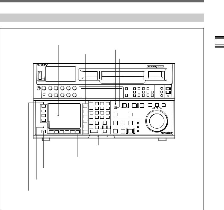
2-1-2 Lower Control Panel (Menu Operations Section)
1Menu display
3MEMORY CARD indicator
2Menu buttons
4ACCESS button |
DIGITALVIDEO CASSETTE RECORDER HDW-F500 |
5Memory card insertion slot
6Function buttons
7ALT button
8MAINTENANCE switch
9ALARM indicator
Lower control panel (menu operations section)
Controls and Parts of Functions and Locations 2 Chapter
Chapter 2 Locations and Functions of Parts and Controls |
2-5 |

Controls and Parts of Functions and Locations 2 Chapter
2-1 Control Panel
1 Menu display
Menus selected by pressing the menu buttons appear here.
Each menu shows the functions assigned to each function button ([F1] to [F10]) and information necessary for making settings, such as time codes.
2 Menu buttons
Press to activate the respective menu.
HOME button: Activates the HOME menu. Settings for basic or editing operations are made in the HOME menu.
TC button: Activates the TC (time code) menu. In the TC menu, you can switch between LTC and VITC and between DF and NDF, and make settings for time code displays on an external monitor.
CUE button: Activates the CUE menu. In the CUE menu, you can register 10 cue points per page for a total of 100 cue points.
PF1 button: Activates the PF (Personal Function) 1 menu. In the PF1 menu, you can register frequently used settings in other menus. Settings for video input/output signals are factory set.
PF2 button: Activates the PF (Personal Function) 2 menu. In the PF2 menu, you can register frequently used settings in other menus. Settings for audio input/output signals are factory set.
SET UP button: Activates the SET UP menu. Use the SET UP menu to restore settings to the VTR memory banks or IC memory card, register functions to the PF1/2 menus, and set items in the VTR SETUP menu.
For details, see Chapter 4, “Menu Settings” on page 4-1.
3 MEMORY CARD indicator
Lights up when the memory card is inserted. The indicator will flash when the memory card is
improperly inserted or when the memory card battery is dead.
4 ACCESS button
Press this button to directly activate the MEMORY CARD menu. Flashes when the control panel is accessing the memory card.
Note
Do not eject the memory card while the ACCESS button is flashing as this may damage the contents of the memory card.
5 Memory card insertion slot
Insert memory cards here. VTR settings can be stored on cards and used to configure the VTR and control panel at a later date, thus reducing the time required for set up.
Press the button beside the insertion slot to eject the memory card.
6 Function buttons
Activates the functions in each menu.
7 ALT (alternative) button
Press to change the functions of the current menu. Press again to return to the original functions.
8 MAINTENANCE switch
Activates the MAINTENANCE menu.
To operate this switch, push it in using the tip of a pen or some other pointed object while holding down the SFT button.
9 ALARM indicator
Flashes when the communication between the VTR and the control panel is abnormal.
2-6 |
Chapter 2 Locations and Functions of Parts and Controls |
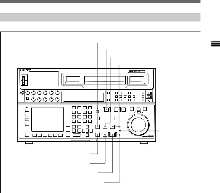
2-1-3 Lower Control Panel (Editing Operations Section)
!ºNumeric buttons and +/– buttons
!¡SFT button
!™RCL button
!£CLR button
!¢SET button
DIGITALVIDEO CASSETTE RECORDER HDW-F500 
@™PREREAD indicator
!∞AUDIO IN/OUT buttons |
@¡PLAYER/RECORDER buttons |
|
|
!§IN/OUT buttons |
@ºINPUT CHECK button |
!¶ENTRY button |
!ªAUTO button |
!•Cursor control buttons |
|
Lower control panel (editing operations section)
Controls and Parts of Functions and Locations 2 Chapter
Chapter 2 Locations and Functions of Parts and Controls |
2-7 |

Controls and Parts of Functions and Locations 2 Chapter
2-1 Control Panel
!º Numeric buttons and +/– buttons
Press to input time data or edit points data at the cursor position in menu display. Press buttons 0 to 5 while holding down the SFT button to input A to F (hexadecimal figures) for user bits. Use the +/– buttons to increase or decrease settings.
!¡ SFT (shift) button
Press buttons 0 to 5 while holding down this button to input A to F (hexadecimal figures) for user bits.
Use also in combination with other buttons to perform other operations.
!™ RCL (recall) button
Press to call up a previously entered value.
!£ CLR (clear) button
Press to clear input data.
!¢ SET button
Press to finalize data.
!∞ AUDIO IN/OUT buttons
Press to set AUDIO IN and OUT points during insert mode. Press either AUDIO IN or OUT button while holding down the ENTRY button to set an audio edit point.
!§ IN/OUT buttons
Press to set an IN or OUT point during editing. Press either button while holding down the ENTRY button to set an edit point.
!¶ ENTRY button
Press to enter an edit or cue point.
While holding down this button, press either the AUDIO IN or OUT button, or the IN or OUT button.
!• Cursor control buttons
Press to move the cursor in the menu display. Move the cursor as required to enter a value using the numeric buttons, or to change a menu setting.
!ª AUTO button
When this button is pressed, it lights up and auto edit mode is activated.
@º INPUT CHECK button
While you hold down this button, the input signal is output from the monitor output connector, so that you can monitor the input video and audio.
When the LTC/VITC time code is shown on the display, you can check the time code generator.
Note
When the optional HKDV-501A HD-SD Converter Board is installed in the unit and VTR SETUP menu item 776 DOWNCONVERTER INPUT CHECK ENABLE is set to “enable”, you can monitor downconverter output. When you press the INPUT CHECK button, the input video and audio is output from all HD-SD converter output connectors.
@¡ PLAYER/RECORDER buttons
Select which VTR is to be controlled by this VTR’s control panel during editing when this VTR is used as a recorder and an external VTR is connected to the REMOTE1-IN(9P)/OUT(9P) connectors as a player.
PLAYER: The tape transport buttons and editing operation buttons on the control panel control the external player VTR.
RECORDER: The tape transport buttons and editing operation buttons on the control panel control the recorder VTR (this VTR).
The PLAYER/RECORDER buttons have no effect when using this VTR alone.
@™ PREREAD indicator
Lights up during preread mode.
For more information about PREREAD, see “6-2-3 Performing Preread Editing” on page 6-18.
2-8 |
Chapter 2 Locations and Functions of Parts and Controls |
2-1-4 Lower Control Panel (Tape Transport Operations Section)
@£STANDBY button
@¢EJECT button |
@∞PREROLL button |
@§PREVIEW/REVIEW button |
DIGITALVIDEO CASSETTE RECORDER HDW-F500 |
@¶SERVO indicator |
@•STOP button
@ªPLAY button
#ºREC/EDIT button
#¡REC INHIBIT indicator
Lower control panel (tape transport operations section)
@£ STANDBY button
Press this button in other than standby mode to make it light up and place the VTR in standby mode. The head drum rotates in standby mode, thereby shortening the time required for the tape to start. Press this button while in standby mode to turn the button off and cancel standby mode. The head drum stops rotating and the tape tension is released. If the VTR remains in standby mode for more than eight minutes (factory setting), standby mode is automatically canceled in order to safeguard the tape.
@¢ EJECT button
Press to eject the cassette. When the button is pressed, the tape is automatically unthreaded and the cassette is ejected in a few seconds. Resets the display when CTL codes appear in the menu display in the lower control panel.
Controls and Parts of Functions and Locations 2 Chapter
Chapter 2 Locations and Functions of Parts and Controls |
2-9 |

Controls and Parts of Functions and Locations 2 Chapter
2-1 Control Panel
@∞ PREROLL button
Press to position the tape to the preroll point (a position factory set to five seconds before the IN point).
Press this button while holding down the IN, OUT, AUDIO IN or AUDIO OUT button to cue up the tape at the edit point of the respective button.
For details on changing the preroll time, refer to “4-2-7 Setting the Preroll Time (PREROLL TIME)” on page 4-18.
@§ PREVIEW/REVIEW button
After edit points are set, press this button to preview, on the monitor connected to the recorder, the effect of the edit before it is performed. In this operation, the tape runs, but no editing is carried out.
If you press this button after carrying out an edit, the results of the edit are played back on the monitor connected to the recorder.
@¶ SERVO indicator
Lights up when the drum servo and capstan servo are locked.
@• STOP button
When you insert the cassette, the VTR automatically enters stop mode.
The STOP button flashes when the [F2] (SERVO REF) button in the PF1 menu is set to input but there is no video input signal, when the [F2] (SERVO REF) button in the PF1 menu is set to ext but there is no external reference video signal, or when the input signal is out of sync with the external reference video signal. If you want, you can set 102. REFERENCE SYSTEM ALARM in the VTR SETUP menu so that the STOP button will not flash under the above conditions.
@ª PLAY button
Starts playback.
Press this button while holding down the REC button to start recording.
Pressing this button during recording or manual editing changes the VTR to playback mode.
#º REC/EDIT (recording/edit) button
Press this button while holding down the PLAY button to start recording.
If you press this button in play mode manual editing begins. After setting edit points, if you press this button while the AUTO button is lit, automatic editing is performed.
#¡ REC INHIBIT indicator
The status of this indicator depends on the setting of the ALT button and [F2] (REC INH) button in the HOME menu and the state of the record-protect plug on the cassette.
Status of the REC INHIBIT indicator
Setting of the ALT |
State of the record- |
REC INHIBIT |
||
and [F2] (REC INH) |
protect plug on the |
indicator |
||
buttons in the |
cassette |
|
||
HOME menu |
|
|
||
all |
Recording disabled |
Lit/flashinga) |
||
|
|
Recording allowed |
Lit |
|
|
|
|
|
|
crash REC, video/ |
Recording disabled |
Lit/flashinga) |
||
CTL, audio/CTL |
|
|
||
Recording allowed |
Unlit |
|||
|
|
|||
|
|
|
|
|
off |
Recording disabled |
Lit/flashinga) |
||
|
|
|
|
|
|
|
Recording allowed |
Unlita) |
|
a)Toggle between lit/flashing settings is possible using the 104.REC INHIBIT LAMP FLASHING setting in the VTR SETUP menu.
Recording, editing, and selection of assemble and insert modes are possible only when the indicator is off.
2-10 |
Chapter 2 Locations and Functions of Parts and Controls |
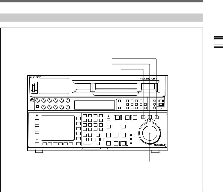
2-1-5 Lower Control Panel (Search Operations Section)
#™ VAR button
#£ JOG button
#¢ SHUTTLE button
DIGITALVIDEO CASSETTE RECORDER HDW-F500 |
#∞ Search dial
Controls and Parts of Functions and Locations 2 Chapter
Lower control panel (search operations section)
#™ VAR button
Press to select variable speed playback mode for noiseless playback in a maximum range of –1 to +2 times normal playback speed, in 51 steps. Playback exceeding this speed range is not possible. The search dial clicks at the positions for still-picture and normal playback speed.
#£ JOG button
Press to select jog mode. In this mode, the button lights up and playback at –1 to +1 or –2 to +2 times normal playback speed is possible (determined by the 107. JOG DIAL RESPONSE setting in the VTR SETUP menu). In this mode, the search dial does not click.
#¢ SHUTTLE button
Press to enter shuttle mode. In this mode, the button lights and playback corresponding to the angle of rotation of the search dial. The playback speed is different depending on the frame frequency of the unit. In this mode, the search dial clicks at the positions for 0 (still-picture), –10 and +10 times normal playback speed.
Frame frequency |
Playback speed |
23.98/24 Hz |
Ranging from –60 to +60 |
|
|
25 Hz |
Ranging from –58 to +58 |
|
|
29.97/30 Hz |
Ranging from –50 to +50 |
|
|
Chapter 2 Locations and Functions of Parts and Controls |
2-11 |

Controls and Parts of Functions and Locations 2 Chapter
2-1 Control Panel
#∞ Search dial
Rotate to search for edit points. Rotate the dial clockwise for forward playback (the z indicator lights up) or counterclockwise for reverse playback (the Z indicator lights up). The p indicator lights up while the VTR is in stop mode.
Shuttle mode: The playback speed is different depending on the frame frequency of the unit. (See item #¢SHUTTLE button.) The dial clicks at the positions corresponding to 0 (still-picture), –10 and +10 times normal playback speed.
Jog mode: The playback speed corresponds to the rotational speed of the dial (–1 to +1 or –2 to +2 times normal playback speed depending on the 107.JOG DIAL RESPONSE setting in the VTR SETUP menu). The dial does not click.
Variable speed playback mode: Noiseless playback at –1 times normal speed when the dial is rotated fully counterclockwise, and +2 times normal speed when rotated clockwise. The dial clicks at the positions of still-picture and normal playback speed.
Capstan override mode: Rotating the dial while holding down the PLAY button changes the playback speed by up to ±15%.
After turning the power on, always set the search dial at the center position (where the p indicator lights up).
2-12 |
Chapter 2 Locations and Functions of Parts and Controls |
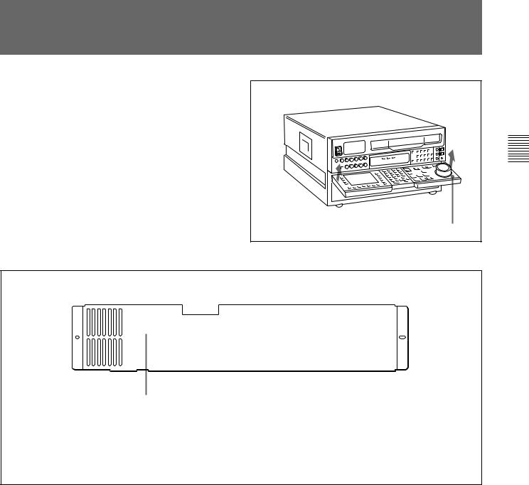
2-2 System Set-Up Panel
Lift the lower control panel up to its horizontal position to access the system set-up panel.
Lower control panel |
Accessing the system set-up panel
C O N T R O L P A N E L
E X T  I N T
I N T
CONTROL PANEL switch
Selects which control panel controls this VTR. INT: Control is by the control panel attached to
this VTR.
EXT: Control is remote, by connection to the CONTROL PANEL connector on the rear panel.
The switch is factory-set to INT.
System set-up panel
Controls and Parts of Functions and Locations 2 Chapter
Chapter 2 Locations and Functions of Parts and Controls |
2-13 |

Controls and Parts of Functions and Locations 2 Chapter
2-23 -Connector3 ConnectorPanel Panel
1D CONV. OUT (OPTION) COMPOSITE (SUPER) connector
2 D CONV. OUT (OPTION) SYNC connector
3REF. IN SD connectors and 75 Ω termination switch
4REF. IN HD connectors and 75 Ω termination switch
5 BREAKER button
6 ⁄AC IN connector and ground connector
7AUDIO INPUT (AES/EBU) connectors
8AUDIO OUTPUT (AES/EBU) connectors
9 HD SDI INPUT connectors
!º HD SDI OUTPUT connectors
!¡ SDTI (OPTION) IN connector
!™ SDTI (OPTION) OUT connector
!£ AUDIO INPUT LEVEL/ 600Ω termination switches
!¢ AUDIO INPUT connectors
!∞ AUDIO OUTPUT connectors
!§ CONTROL PANEL connector
!¶ REMOTE1-IN(9P)/OUT(9P) connectors
!• MONITOR OUTPUT connectors
!ªVIDEO CONTROL connector
@ºRS-232C connector
@¡PARALLEL I/O (50P) connector
@™D CONV. SDI OUT (OPTION) connectors
@£PULL DOWN OUT (OPTION) connector
@¢TIME CODE OUT connector
@∞TIME CODE IN connector
Connector panel
Note |
|
connectors, the type (male or female) of input/output |
For the AUDIO INPUT CH1/2/3/4 CUE connectors, |
connectors used overseas are opposite of those used in |
|
AUDIO OUTPUT CH1/2/3/4/CUE connectors, as well |
Japan. To use this unit with audio equipment outside |
|
as the TIME CODE IN/OUT (XLR, 3 pins) |
of Japan, you must use male/female adapters. |
|
2-14 |
Chapter 2 Locations and Functions of Parts and Controls |

1D CONV. OUT (OPTION) COMPOSITE (SUPER) connector (BNC)
Outputs an analog composite signal for a video monitor. When the ALT/[F6] (CHARA SUPER) setting in the TC menu is on, character signals such as time codes are superimposed on the output.
Note
This connector is operative only when the optional HKDV-501A HD-SD Converter Board is installed.
2D CONV. OUT (OPTION) SYNC connector (BNC)
Outputs an NTSC external sync signal.
Notes
•This is effective only when the optional HKDV-501A HD-SD Converter Board is installed.
•The phase is the same as the phase of the composite signal output from the COMPOSITE (SUPER) of D CONV. OUT (OPTION) connector. Because the output phase changes with the operation mode of the VTR, use this to synchronize with the video monitor.
3REF. IN SD connectors (BNC) and 75 Ω termination switch
Inputs for a reference video signal (NTSC or PAL) of the selected field frequency. Use a video signal with chroma burst (VBS) or a monochrome video signal (VS).
A loop-through connection is possible. Set the 75 Ω termination switch to OFF if you are using a loopthrough connection and set it to ON if you are not using a loop-through connection.
4 REF. IN HD connectors (BNC) and 75 Ω termination switch
Inputs for a reference video signal (HD) of the selected field frequency. Use a trilevel SYNC signal for the external synchronization. A loop-through connection is possible. Set the 75 Ω termination switch to OFF if you are using a loop-through connection and set it to ON if you are not using a loop-through connection.
5 BREAKER button
Primary circuit breaker for the AC power circuit.
6 ⁄AC IN connector and connector
Connects to an AC outlet using the power cord supplied with the VTR.
7 AUDIO INPUT (AES/EBU) connectors (BNC)
Inputs for digital signals in AES/EBU format for channels 1 to 4.
8 AUDIO OUTPUT (AES/EBU)connectors (BNC)
Outputs digital signals in AES/EBU format for channels 1 through 4.
9HD SDI (SDI video/audio) INPUT connectors (BNC)
The left connector accepts HD SDI video/audio signals.
Note
The INPUT MONITOR connector is for use with an input monitor and does not follow the standards for output.
!º HD SDI (SDI video/audio) OUTPUT connectors
(BNC)
Outputs up to four (1 to 4) HD SDI video/audio signal lines.
Character data such as time codes are superimposed on the signal from the MONITOR connector when the ALT/[F6] (CHARA SUPER) setting in the TC menu is set.
!¡ SDTI (OPTION) IN connector (BNC)
Outputs a video/audio SDTI signal.
Note
This connector is operative only when the optional HKDV-506A SDTI Board is installed.
!™ SDTI (OPTION) OUT connector (BNC)
Inputs a video/audio SDTI signal.
Note
This connector is operative only when the optional HKDV-506A SDTI Board is installed.
Controls and Parts of Functions and Locations 2 Chapter
Chapter 2 Locations and Functions of Parts and Controls |
2-15 |

Controls and Parts of Functions and Locations 2 Chapter
2-3 Connector Panel
!£ AUDIO INPUT LEVEL/600Ω termination switches
The termination switches should be set for in ANALOG AUDIO INPUT connector according to the audio input level and input impedance.
Use OFF for low input levels when:
Audio input level is –60 dBu (microphone input) and audio input impedance is high (approximately 20 kΩ )
Use OFF for high input levels when:
Audio input level is +4 dBu (line input) and audio input impedance is high (approximately 20 kΩ )
Use ON for high input levels when:
Audio input level is +4 dBm (line input) and audio input impedance is 600Ω
!¢ ANALOG AUDIO INPUT connectors
(XLR-3-32)
Accepts up to five analog audio signal lines (channels 1 to 4 and cue).
!∞ ANALOG AUDIO OUTPUT connectors
(XLR-3-31)
Outputs up to five analog audio signal lines (channels 1 to 4 and cue).
!§ CONTROL PANEL connector (15-pin)
Connects the control panel through the 15-pin cable when using the control panel is used as a remote controller.
!¶ REMOTE1-IN (9P)/OUT (9P) connectors
(D-sub 9-pin)
Used with the included 9pin remote control cable to connect two HDW-F500 VTRs, or a second HD VTR when a BVE900/910/2000/9000/9100 series BVE Editing Control Unit is used for editing. Used when you edit using two VTRs and the BVE-900/910/2000/ 9000/9100 Editing Control Unit. The REMOTE1-IN and OUT connectors can be used to make a bridge connection.
!• MONITOR OUTPUT connectors (XLR-3-31)
Outputs signals for audio monitoring. These connectors output two signal lines: L and R. Select the signals to be output with the MONITOR SELECT buttons and the AUDIO INPUT/MONITOR SELECT buttons on the upper control panel. A setting can be made so that volume can be controlled with the PHONES volume knob.
For details, see Section 5-1-2, “Selecting Audio Signals”on page 5-2.
!ª VIDEO CONTROL (Digital Video Processor
Control) connector (D-sub 9-pin)
Connects to the optional HKDV-503 HD Digital Video Controller to enable remote control of the internal digital video processor. Turn off the power before connecting the remote controller.
@º RS-232C connector (RS-232C serial interface)
(D-sub 25-pin)
Receives or transmits RS-232C serial remote control signals and/or VTR status data from/to external equipment. When this connector is being used for communication, the RS-232C indicator on the upper control panel will be lit.
@¡ PARALLEL I/O (50P) connector (D-sub 50-pin, with optional BKDW-509)
Inputs an external remote control signal.
For details, refer to the Maintenance Manual.
@™ D CONV. SDI (D1/D2 SDI video/audio)
(OPTION) OUT connectors (BNC)
Outputs up to three sets of video/audio signals. When the ALT/[F8] (CHARA SUPER) key of the TC menu is set to ON, text data such as time codes are superimposed on the output of connector 3 (SUPER). Selection of D1/D2 output is made using the [F9] (OTHERS CHECK)/[F9] (SYSTEM)/[F3] (D-CONV SDI) button in the MAINTENANCE menu.
Note
This connector is operative only when the optional HKDV-501A HD-SD Converter Board is installed.
2-16 |
Chapter 2 Locations and Functions of Parts and Controls |
Loading...