


 Loading...
SIMATIC
PC Adapter
TS Adapter
Quick Reference Guide
Edition 01/2003
A5E00078070-02

Exclusion of Liability
We have checked the contents of this manual for agreement with the hardware and software described. Since deviations cannot be precluded entirely, we cannot guarantee full agreement. However, the data in this manual are reviewed regularly and any necessary corrections included in subsequent editions. Suggestions for improvement are welcomed.
Technical data subject to change.
Copyright E Siemens AG 2000 2003 All Rights Reserved
The reproduction, transmission or use of this document or its contents is not permitted without express written authority. Offenders will be liable for damages. All rights, including rights created by patent grant or registration of a utility model or design, are reserved.
Siemens Aktiengesellschaft
A5E00078070
Printed in the Fed. Rep. of Germany
Contents
1 Product Definition . . . . . . . . . . . . . . . . . . . . . . . . . . . . . . . 1 2 Package Components . . . . . . . . . . . . . . . . . . . . . . . . . . . 4 3 Accessories . . . . . . . . . . . . . . . . . . . . . . . . . . . . . . . . . . . . 4 4 MPI/DP Network . . . . . . . . . . . . . . . . . . . . . . . . . . . . . . . . . 4
5 Prerequisites for Operation . . . . . . . . . . . . . . . . . . . . . . . 5
5.1 Hardware . . . . . . . . . . . . . . . . . . . . . . . . . . . . . . . . . 5 5.2 Software . . . . . . . . . . . . . . . . . . . . . . . . . . . . . . . . . . 5
6 Connecting the Adapter . . . . . . . . . . . . . . . . . . . . . . . . . . 6
6.1 Safety-related Guidelines . . . . . . . . . . . . . . . . . . . . 6 6.2 General Remarks . . . . . . . . . . . . . . . . . . . . . . . . . . 7 6.3 Pin Configuration . . . . . . . . . . . . . . . . . . . . . . . . . . 10 6.4 Connection Procedures . . . . . . . . . . . . . . . . . . . . 12 6.5 Function and Operation of the Switch . . . . . . . . 13 6.6 Function of the Power LED . . . . . . . . . . . . . . . . . 14
7 Technical Specifications . . . . . . . . . . . . . . . . . . . . . . . . 15
7.1 Supplied PC/TS Adapter Versions . . . . . . . . . . . 17 7.2 Features of the PC/TS Adapter Versions . . . . . . 18
8 Approvals . . . . . . . . . . . . . . . . . . . . . . . . . . . . . . . . . . . . . 20
8.1 Approval for USA and Canada . . . . . . . . . . . . . . 20 8.2 Approvals for Europe . . . . . . . . . . . . . . . . . . . . . . 22
PC/TS Adapter |
i |
A5E00078070-02 |
PC/MPI Cable |
Kurzanleitung |
ii |
PC/TS Adapter |
A5E00078070-02 |
Quick Reference Guide |
PC/TS Adapter |
1 Product Definition
The adapter is available as:
SPC adapter 6ES7 972-0CA2x-0XA0 or
STS adapter 6ES7 972-0CA3x-0XA0
Note
Where ’adapter’ is referred to below, the text applies to both variants.
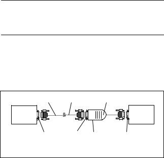
The PC adapter connects a PC to the MPI/DP interface (Multipoint Interface) via the serial COM port of an S7/M7/C7 system.
This does not require a PC slot, that is, the adapter is also suitable for use in non-expandable PCs such as notebooks.
1) |
19.2/38.4 kbps |
PC adapter |
PC |
S7/M7/C7 |
|
system |
||
|
RS232 |
RS232 Switch |
MPI/DP |
COM 1 ... |
19.2/38.4 kbps |
|
1)RS232 cable 6ES7 901-1BF00-0XA0, length 6m
Figure 1-1 PC Adapter in the System
PC/TS Adapter |
1 |
A5E00078070-02 |
PC/TS Adapter |
Quick Reference Guide |
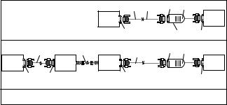
With ’direct connection’, the TS adapter allows you to link programming devices/PCs with S7/M7/C7 systems. With this setup, the TS adapter corresponds in functionality to the PC adapter.
With ’modem connection’, the TS adapter enables you to link programming devices/PCs with S7/M7/C7 systems over the telephone network.
Direct Connection
1) |
19.2/38.4 kb |
RS232 TS adapter |
|
|
PC |
S7/M7/C7 |
|
system |
||
|
RS232 |
Switch |
MPI/DP |
COM1... |
19.2/38.4 kbps |
|
Modem Connection
|
2) |
Telephone network |
|
RS232 TS adapter |
|
|
|
2) |
|||
|
|
|
|
||
PG/PC |
|
Modem |
Modem |
|
S7/M7/C7 |
|
|
system |
|||
RS232 |
|
RS232 |
|
RS232 |
MPI/DP |
COM1... |
|
|
|
|
|
1)RS232 cable 6ES7 901-1BF00-0XA0, length 6m
2)Modem cable (supplied with modem)
Figure 1-2 TS Adapter in the System
The TeleService optional package is always required to operate the TS adapter (see 5.2 Software). The switch on the adapter is used to change the transmission rate on the RS232 side in direct connection. With modem connection, it has no function.
2 |
PC/TS Adapter |
A5E00078070-02 |
Quick Reference Guide |
PC/TS Adapter |
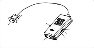
Adapter |
|
|
MPI/DP connector |
LED “POWER” |
|
|
||
|
LED “ACTIVE” |
|
RS232 connector |
Switch |
|
“19.2/38.4 kbps” |
||
|
Figure 1-3 Adapter
The two adapter types differ with respect to the location of the MPI/DP parameters:
SThe MPI/DP parameters for the PC adapter are set in “Set PG/PC interface”. When opening an online display for the first time, ther parameters are transferred to the PC adapter.
SThe MPI/DP parameters for the TS adapter are set via a Teleservice application and stored permanently on the TS adapter. When opening an online display for the first time, these parameters are activated.
PC/TS Adapter |
3 |
A5E00078070-02 |

PC/TS Adapter Quick Reference Guide
2 |
Package Components |
S |
Adapter |
S |
Quick Reference Guide |
S Mounting assembly (TS adapter only) |
|
3 |
Accessories (not part of the adapter package) |
S RS232 cable, 6 meters in length 6ES7 901-1BF00-0XA0 (required to operate the PC adapter and to operate the TS adapter in direct connection only).
4 MPI/DP Network
A maximum of 32 nodes can be interfaced to an MPI/DP network segment. The total cable length may not exceed 50 meters. Using so-called RS485 repeaters, several network segments can be combined to form a network comprising a maximum of 127 nodes.
The data signalling rate in an MPI/DP network is max. 12 Mbit/s.
Der Adapter unterstützt Übertragungsraten bis max. 1,5 Mbit/ s.
Note
Also refer to “S7-300, Hardware and Installation”.
!If the transmission rate is 187.5 Kbits/sec and higher, it is not allowed to insert cable extensions
in the S7/M7/C7 adapter system connection (spur lines not allowed).Warning
4 |
PC/TS Adapter |
A5E00078070-02 |

Quick Reference Guide |
PC/TS Adapter |
5 Prerequisites for Operation
5.1Hardware
PC/programming device with a free COM port (COM1 or COM2, 9-pin COM connection). Appropriate adapters for other connector combinations are available in specialist shops, for example 9-pin to 25-pin subminiature D connector.
25-pin subminiature D: |
Signal: |
|
9-pin subminiature D: |
|
|
|
|
Shield |
|
Shield |
|
8 |
DCD |
|
1 |
|
|
||
3 |
RXD |
|
2 |
|
|
||
2 |
TXD |
|
3 |
|
|
||
20 |
DTR |
|
4 |
|
|
||
7 |
GND |
|
5 |
|
|
||
6 |
DSR |
|
6 |
|
|
||
4 |
RTS |
|
7 |
|
|
||
5 |
CTS |
|
8 |
|
|
||
22 |
RI |
|
9 |
|
|
||
Shield |
|
Shield |
|
1) |
|
|
1) |
Connector casing |
|
Connector casing |
|
|
|
1)Pins or sockets, depending on usage
Figure 1-4 9-Pin - 25-Pin RS232 Adapter
5.2Software
PC adapter
SSTEP 7 Standard Package from V1 or
SS7 DOS
TS adapter
SSTEP 7 Standard Package from V3.1 and
STeleService optional package from Version 3.0
PC/TS Adapter |
5 |
A5E00078070-02 |
Loading...