


VC-A560U(A)/A560U/A560U(B)
VC-H960U/H960U(B)/H961U
SUPPLEMENT
SERVICE MANUAL
S62K7VC-A560U
SUPPLEMENT


 VIDEO CASSETTE RECORDER
VC-A560U(A)/A560U/A560U(B)
VC-H960U/H960U(B)
VC-H961U
VC-A560U(A) VC-A560U/A560U(B) VC-H960U/H960U(B)
MODELS VC-H961U
In the interests of user-safety (Required by safety regulations in some countries) the set should be restored to its original condition and only parts identical to those specified be used.
OUTLINE
This Supplement describes corrections of the mechanism in the VC-A560U(A)/A560U/A560U(B)/H960U/ H960U(B)/H961U Service Manual already issued. For the items which are not described in this Supplement, refer to the VC-A560U(A)/A560U/A560U(B)/H960U/H960U(B)/H961U Service Manual (S3292VC-A560U).
|
CONTENTS |
|
|
|
Page |
2. |
DISASSEMBLY AND REASSEMBLY ........................................................................................... |
2 |
3. |
FUNCTION OF MAJOR MECHANICAL PARTS ........................................................................... |
4 |
4. |
ADJUSTMENT, REPLACEMENT AND ASSEMBLY OF MECHANICAL UNITS .......................... |
6 |
6. |
MECHANISM OPERATION FLOWCHART AND TROUBLESHOOTING GUIDE ...................... |
25 |
VC-A560U/H960U/H961U ..................................................................... |
Models for Canada |
VC-A560U(A)/A560U/A560U(B)/H960U/H960U(B) .............................. |
Models for U.S.A |
This document has been published to be used for SHARP CORPORATION after sales service only.
1The contents are subject to change without notice.
VC-A560U(A)/A560U/A560U(B)
VC-H960U/H960U(B)/H961U
SUPPLEMENT
2. DISASSEMBLY AND REASSEMBLY
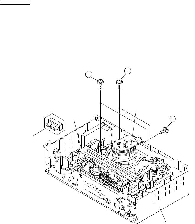
2-2 DISASSEMBLING THE MECHANISM
1.When removing the mechanism from the set.
Remove the screw 2 which connecting the PWB and
the mechanism.
Remove the screw 4which connecting mechanism and main frame.
Take out vertically the mechanism so that it does not damage the adjacent parts.
3
2.Removing the mechanism and cassette housing. Remove 2 screws 3fixing the cassette housing to the mechanism, and remove the cassette housing.
4
MECHANISM CHASSIS
CASSETTE
HOUSING
2
VC-H961U
MAIN FRAME
2

2-3 CARES WHEN REASSEMBLING
INSTALLING THE CASSETTE HOUSING
When the cassette housing is installed on the mechanism, the initial setting is essential condition.
There are two initial setting methods, namely electrical and mechanical.
1. Electrical initial setting
So as to perform initial setting of mechanism execute the Step 1 of Installation of cassette housing. After ascertaining the return to the initial setting position install the cassette housing. (Conditions: When mechanism and PWB have
been installed)
Main Chassis
Pinch Drive Cam
Synchro Gear |
Master cam |
Drive Lever |
2. Mechanical initial setting
•Rotate the worm gear by pushing the flange manually until return to initial position.
INSTALLING THE MECHANISM ON PWB
Lower vertically the mechanism, paying attention to the mechanism edge mode SW position, (Set the mode SW position to 270° and make sure the master cam position hole also in 270° position) and install the mechanism with due care so that the parts are not damaged.
*Please make sure to insert correctly.
If not, strange moving will occur and will couse mechanism damage.
VC-A560U(A)/A560U/A560U(B)
VC-H960U/H960U(B)/H961U
SUPPLEMENT
Rotate the flange of worm gear by using thin stick. CW • • • Loading direction
CCW • • • Ejection direction Note
Be careful not to damage the gear of worm gear and worm wheel gear. It might cause a strange sound.
•When apply power supply to rotate the loading motor, please remove/unsolder at least one terminal wire.
•If voltage applied to loading motor without disconnecting the terminal wire, there is a possibility the capstan motor IC will damage.
•The maximum applied voltage is 9V. If more than 9V, there is a possibility the mechanism will damage.
•After ascertaining the return to the initial set position install the cassette housing in the specified position. (This method is applied only for the mechanism.)
PARTS WHICH NEED PARTICULAR CARE
When installing the mechanism chassis on the PWB unit, take care so as to prevent deformation due to contact of mechanism chassis with REC TIP SW.
END SENSOR |
AE CONNECTOR |
|
VC-H961U |
AH CONNECTOR |
|
AA CONNECTOR |
||
|
AD CONNECTOR
AC CORD
START SENSOR


 END TIP SW
90°
180° 

 0°
0°
270°
This positioning hole MODE SW  should be at front side.
MASTER CAM POSITION
3

VC-A560U(A)/A560U/A560U(B)
VC-H960U/H960U(B)/H961U
SUPPLEMENT
3. FUNCTION OF MAJOR MECHANICAL PARTS (TOP VIEW)
1
2
3
7
17 |
15 |
26 |
18 |
10 |
16 |
14
9

 11
11
5
8
6 |
12 |
4 |
13 |
No. |
Function |
No. |
Function |
|
|
|
|
1 |
Full erase head |
11 |
Reverse guide lever ass’y |
2 |
Supply pole base ass’y |
12 |
Reel relay gear |
3 |
Tension arm |
13 |
Take-up reel disk |
4 |
Idler wheel ass’y |
14 |
Pinch roller lever ass’y |
5 |
Open guide |
15 |
Drum ass'y |
6 |
Supply reel disk |
16 |
Loading motor block |
7 |
Supply main brake |
17 |
Drum driver motor |
8 |
Take-up main brake |
18 |
Take-up pole base ass'y |
9 |
Pinch drive cam |
26 |
Auto head cleaner Ass'y |
10 |
A/C head ass’y |
|
|
|
|
|
|
4
VC-A560U(A)/A560U/A560U(B)
VC-H960U/H960U(B)/H961U
SUPPLEMENT
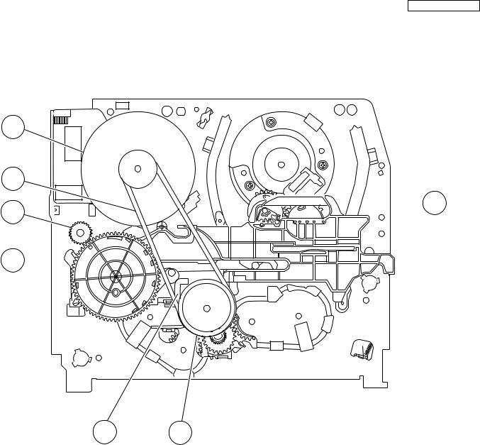
FUNCTION OF MAJOR MECHANICAL PARTS (BOTTOM VIEW)
21
22 

 19
19 


 25
25
20 
23 24
No. |
Function |
No. |
Function |
|
|
|
|
19 |
Syncro Gear |
23 |
Clutch lever |
20 |
Master cam |
24 |
Limiter pulley ass’y |
21 |
Capstan D.D. motor |
25 |
Shifter |
22 |
Reel belt |
|
|
|
|
|
|
5
VC-A560U(A)/A560U/A560U(B)
VC-H960U/H960U(B)/H961U
SUPPLEMENT
4. ADJUSTMENT, REPLACEMENT AND ASSEMBLY OF MECHANICAL UNITS
The explanation given below relates to the on-site general service (field service) but it does not relates to the adjustment and replacement which need high-grade equipment, jigs and skill. For example, the drum assembling, replacement and adjustment service must be performed by the person who have finished the technical courses.
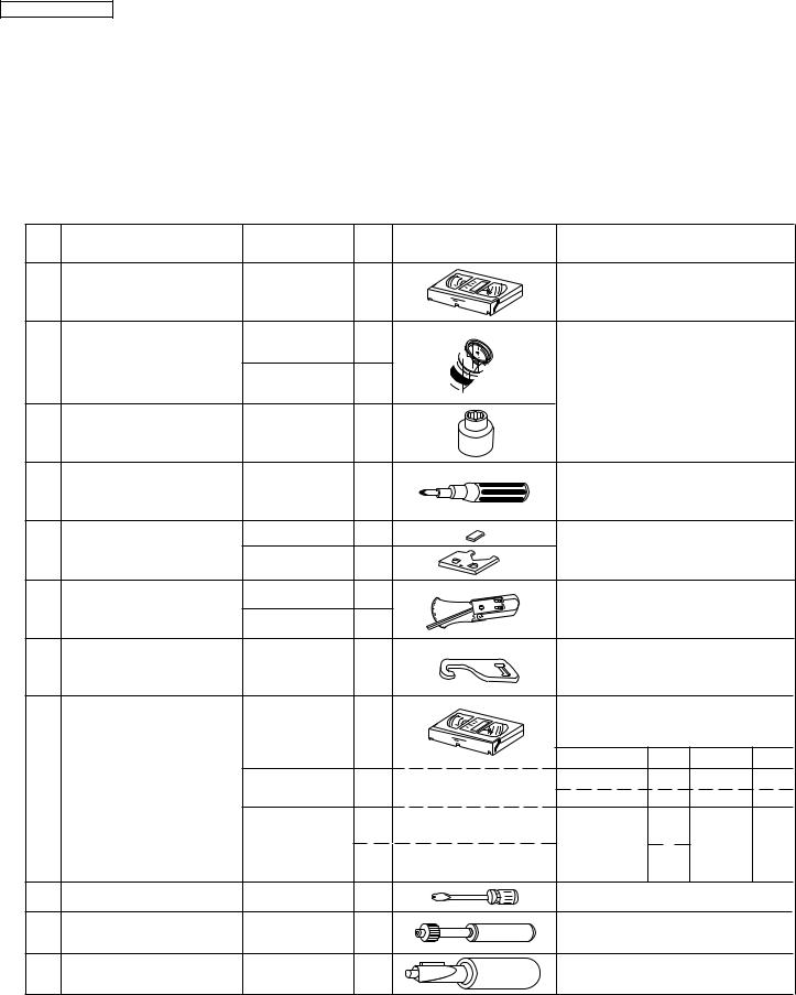
4-1 MECHANISM CONFIRMATION ADJUSTMENT JIG
So as to perform completely the mechanism adjustment prepare the following special jigs. So as to maintain the initial performance of the machine the maintenance and check are necessary. Utmost care must be taken so that the tape is not damaged. If adjustment needs any jig, be sure to use the required jig.
No. |
Jig ltem |
Part No. |
Code |
Configuration |
Remarks |
|
||
1. |
Torque Cassette Meter |
JiGVHT-063 |
CZ |
This cassette torque meter is used for check- |
||||
ing and adjusting the torque of take-up for |
||||||||
|
|
|
|
measuring tape back tension. |
|
|||
|
|
JiGTG0090 |
CM |
|
|
|
|
|
2. |
Torque Gauge |
|
|
These Jigs are used for checking |
||||
|
|
JiGTG1200 |
CN |
|||||
|
|
and adjusting the torque of take-up |
||||||
|
|
|
|
|||||
|
|
|
|
and supply reel disks. |
|
|||
3. |
Torque Gauge Head |
JiGTH0006 |
AW |
|
|
|
|
|
4. |
Torque Driver |
JiGTD1200 |
CB |
When fixing any part to the threaded |
||||
hole using resin with screw, use the |
||||||||
|
|
|
|
jig. (Specified torque 5 kg) |
|
|||
|
Master Plane Jig and |
JiGRH0002 |
BR |
These Jigs are used for checking |
||||
5. |
Reel Disk Height |
|
|
|||||
JiGMP0001 |
BY |
and adjusting the reel disk height. |
||||||
|
Adjusting Jig |
|||||||
|
|
|
|
|
||||
|
|
JiGSG2000 |
BS |
There are two gauges used for the |
||||
6. |
Tension Gauge |
JiGSG0300 |
BF |
tension measurements, 300 g and |
||||
|
|
2.0 kg. |
|
|
|
|||
|
Pinch pressing force |
|
|
This Jig is used with the tension |
||||
7. |
JiGADP003 |
BK |
gauge. Rotary transformer clearance |
|||||
measuring jig |
||||||||
|
|
|
adjusting jig. |
|
|
|
||
|
|
|
|
|
|
|
||
|
|
|
|
These tapes are especially used for |
||||
|
|
|
|
electrical fine adjustment. |
|
|||
|
|
|
|
Video |
Audio |
HiFi Audio |
Track |
|
8. |
Alignment Tape |
VROATSV |
CD |
525 Monoscope |
7k |
— |
58 m |
|
NTSC Color Bar |
1k |
— |
58 m |
|||||
|
|
|
|
|||||
|
|
VROEFZCS |
BG |
Black Level |
1k |
|
|
|
|
|
OR |
|
|
— |
19 m |
||
|
|
|
(only SYNC) signal |
|
||||
|
|
VROEFZHS |
BH |
|
2.3k |
|
|
|
9. |
Guide roller height |
JiGDRiVERH-4 |
AP |
This screwdriver is used for adjusting the |
||||
adjustment driver |
guide roller height. |
|
|
|||||
|
|
|
|
|
||||
10. |
X value adjustment |
JiGDRiVER-6 |
BM |
For X value adjustment |
|
|||
gear driver |
|
|||||||
|
|
|
|
|||||
11. |
Tension Pole |
JiGHMEC-M005 |
CK |
This Jig is used for adjustment |
||||
|
Adjustment Driver |
|
|
of tension pole. |
|
|
||
|
|
|
|
6 |
|
|
|
|

VC-A560U(A)/A560U/A560U(B)
VC-H960U/H960U(B)/H961U
SUPPLEMENT
4-2 MAINTENANCE CHECK ITEMS AND EXECUTION TIME
Perform the maintenance with the regular intervals as follows so as to maintain the quality of machine.
|
Maintained |
500 |
1000 |
1500 |
2000 |
Possible symptom |
Remarks |
Parts |
|
hrs. |
hrs. |
hrs. |
hrs. |
encountered |
|
|
|
||||||
|
|
|
|
|
|
|
|
Guide roller ass’y |
|
|
|
|
|
Abnormal rotation or significant |
|
|
|
|
|
|
vibration requires replacement. |
||
|
|
|
|
|
|
|
|
Sup guide shaft |
|
|
|
|
Lateral noises Head |
|
|
|
|
|
|
|
|
|
|
Reverse guide |
|
|
|
|
occasionally blocked |
Clean tape contact part with the |
|
|
|
|
|
|
specified cleaning liquid. |
||
|
|
|
|
|
|
|
|
Slant pole on pole base |
|
|
|
|
|
|
|
|
|
|
|
|
|
|
|
Full erase head |
|
|
|
|
Colour and beating |
|
|
|
|
|
|
|
|
|
|
A/C head |
|
|
|
|
|
Small sound or sound |
|
|
|
|
|
|
distortion |
|
|
|
|
|
|
|
|
Clean tape contact area with the |
|
|
|
|
|
|
|
Poor S/N ratio, no colour |
|
|
|
|
|
|
|
specified cleaning liquid. |
|
Upper and lower drum ass’y |
|
|
|
|
Poor flatness of the |
||
|
|
|
|
|
|||
|
|
|
|
envelope with alignment |
|
||
|
|
|
|
|
|
|
|
|
|
|
|
|
|
tape |
|
|
|
|
|
|
|
|
|
Capstan D.D. motor |
|
|
|
|
No tape running, |
|
|
|
|
|
|
uneven colour |
|
||
|
|
|
|
|
|
|
|
Pinch roller |
|
|
|
|
|
No tape running, tape |
|
|
|
|
|
|
slack |
Clean rubber and rubber contact |
|
|
|
|
|
|
|
||
Reel belt |
|
|
|
|
|
No tape running, tape |
area with the specified cleaning |
|
|
|
|
|
slack, no fast forward/ |
liquid. |
|
|
|
|
|
|
|
rewind motion |
|
Tension band ass’y |
|
|
|
|
Screen swaying |
|
|
|
|
|
|
|
|
|
|
Loading motor |
|
|
|
|
Cassette not loaded or |
|
|
|
|
|
|
unloaded |
|
||
|
|
|
|
|
|
|
|
Idler ass’y |
|
|
|
|
|
No tape running, tape |
|
|
|
|
|
|
|
|
|
Limiter pulley |
|
|
|
|
slack |
|
|
|
|
|
|
|
|
||
|
|
|
|
|
|
|
|
Supply/take-up main brake levers |
|
|
|
|
Tape slack |
|
|
|
|
|
|
|
|
|
|
NOTE |
: Part replacement. |
: Cleaning |
: Apply grease |
|
|||
<Specified> Cleaning liquid Industrial ethyl alcohol
*This mechanism does not need electric adjustment with variable resistor. Check parts. If any deviation is found, clean or replace parts.
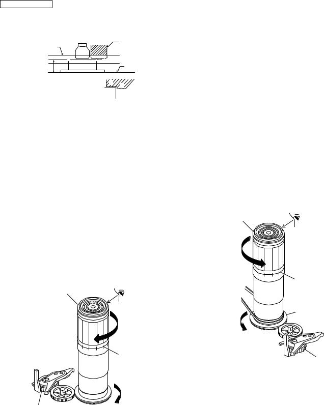
Video head cleaning procedure
1.Apply one drop of cleaning liquid to the cleaning paper with the baby oiler.
2.Gently press the cleaning paper against the video head to fix your finger, and move the upper drum so that each head is passed to and fro 5 times (do not move the cleaning paper).
3. Wipe with the dry cleaning paper.
Notes :
•Use the commercially available ethanol of Class 1 as cleaning liquid.
•Since the video head may be damaged, do not move up and down the cleaning paper.
•Whenever the video head is cleaned, replace the cleaning paper.
•Do not apply this procedure for the parts other than the video head.
 Rotate the upper drum with one hand.
Gently press the cleaning paper to fix with your finger, and rotate the
upper drum to clean.
Move to and fro 5 times for each head. (Do not move the cleaning paper.)
Parts Code |
Description |
Code |
ZPAPRA56-001E |
Cleaning Paper |
AW |
ZOiLR-02-24TE |
Babe Oiler (Spoit) |
AH |
7
VC-A560U(A)/A560U/A560U(B)
VC-H960U/H960U(B)/H961U
SUPPLEMENT
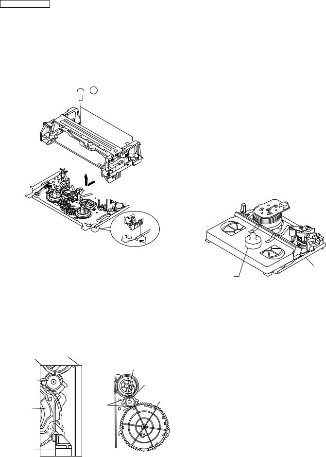
4-3 REMOVING AND INSTALLING THE CASSETTE HOUSING
• Removal
1.In the cassette removing mode, remove the cassette.
2.Unplug the power cord.
3.Remove in the following numerical order.
a)Remove two screws 1.
b)Pull and circle the drive lever and pull up the cassette housing control.
 1
1
Figure 4-1.
• Reassembly
1.Before installing the cassette housing control, shortcircuit between TP803 and TP802 provided at main PWB, press the eject button. The master cam turns and stop in eject position. Fit the drive lever to master cam through main chassis, push down and slide the drive lever towards to master cam.
*Eject position: Pinch Drive Cam positioning hole parallel to center of Synchro Gear (Synchro gear marking line). Synchro Gear positioning mark parallel to center of master cam.
Pinch Drive |
Main chassis |
|
Cam |
Hole of Pinch |
|
|
||
|
drive cam. |
|
Synchro |
Line of |
|
Gear |
synchro |
|
|
gear. |
|
|
Master cam |
|
Master |
Phase |
|
matching |
||
cam |
||
|
Drive
Lever
From top view |
From Bottom View |
Figure 4-2.
2. Install in the reverse order of removal.
Notes
1.In the case when you use the magnet screw driver, never approach the magnet driver to the A/C head, FE head, and drum.
2.When installing or removing, take care so that the cassette housing control and tool do not contact the guide pin or drum.
3.After installing the cassette housing control once perform cassette loading operation.
4-4 TO RUN A TAPE WITHOUT THE CASSETTE HOUSING CONTROL ASSEMBLY
1.Remove the full-surface panel.
2.Short-circuit between TP803 and TP802.
3.Plug in the power cord.
4.Turn off the power switch.
(The pole bases move into U.L.position.)
5.Open the lid of a cassette tape by hand.
6.Hold the lid with two pieces of vinyl tape.
7.Set the cassette tape in the mechanism chassis.
8.Stabilize the cassette tape with a weight (500g) to prevent floating.
500g
Mechanism chassis
Weight to prevent float (500g)
Figure 4-3.
9.Turn on the power switch.
10.Perform running test.
Note:
The weight should not be more than 500g.
To take out the cassette tape.
1.Turn off the power switch.
2.Take out the cassette tape.
8

4-5 REEL DISK REPLACEMENT AND HEIGHT CHECK
• Removal
1.Remove the cassette housing control assembly.
2.Remove the Supply/Take-up main brake ass'y.
3.Remove tension band from the tension arm ass'y.
4.Remove the reel disk.
Note:
Take care so that the tension band ass'y and main brake ass'y are not deformed.
Tension arm ass'y |
Take-up main brake ass'y |
Supply main brake |
|
Tension band |
|
ass'y |
|
VC-A560U(A)/A560U/A560U(B)
VC-H960U/H960U(B)/H961U
SUPPLEMENT
Notes:
1.When installing the reel disk, take due care so that the tension band ass'y is not deformed and grease does no adhere.
2.Do not damage the Supply main brake ass'y. Be careful so that grease does not adhere to the brake surface.
• Reassembly (Take-up reel disk)
1.Clean the reel disk shaft and apply grease (SC-141) to it.
2.Align the phase of the reel disk to that of the reel relay gear and to install a new take-up reel disk onto the shaft.
3.Check the reel disk height and reassemble the take-up
main brake ass'y.
Note:
1.Take care so that the Take-up main brake ass'y is not damaged. Take care so that grease does not adhere the brake surface.
2.After reassembly, check the video search rewind back tension (see 4-10), and check the brake torque (see 4- 14).
|
|
• |
Height checking and adjustment |
|
|
|
|
Note: |
|
|
|
1. |
Set the master plane with due care so that it does not |
|
Supply reel disk |
Take-up reel disk |
|
contact the drum. |
|
2. |
When putting the master plane, shift the reverse guide |
|||
|
|
a little in the loading direction. Care must be taken since excessive shift results in damage.
• Reassembly (Supply reel disk)
1.Clean the reel disk shaft and apply grease (SC-141) to it.
2.Match the phases of reel disk and reel relay gear, and set the new reel disk.
3.After checking the reel disk height, wind the tension band ass'y around the reel disk, and hook to tension arm ass'y.
4.Assemble the Supply main brake ass'y.
Master plane
Supply reel disk
Cassette lock release shaft
Take-up reel disk
Figure 4-4.
Note:
•Check that the reel disk is lower than part A but higher than part B. If the height is not correct, readjust the reel disk height by changing the poly-slider washer under the reel disk.
9
VC-A560U(A)/A560U/A560U(B)
VC-H960U/H960U(B)/H961U
SUPPLEMENT
Note:
Whenever replacing the reel disk, perform the height checking and adjustment.
Master plane |
|
Reel disk height |
|
adjusting jig |
|
|
|
|
10 ± 0.2mm |
Reel disk |
Mechanism chassis |
|
A
B
Reel disk
Figure 4-5.
4-6 CHECKING AND ADJUSTMENT OF TAKEUP TORQUE IN FAST FORWARD MODE
•Remove the cassette housing control assembly.
•After short-circuiting between TP803 and TP802 provided at operation PWB, plug in the power cord.
•Setting
1.Set a torque gauge to zero on the scale. Place it on the take-up reel disk.
2.Press the FF button.
3.To calculate the remaining capacity of the play back mode, slowly rotate the supply reel disk, and then shift it into the forward mode.
• Checking
1.Turn the torque gauge slowly (one rotation every 2 to 3 seconds) by hand in the CW direction.
2.Make sure that the indication of torque gauge is not less than 25mN·m (255gf·cm).
Torque gauge
CW
25mN·m (255gf·cm) or more
The gauge is held at its maximum value. (Red mark)
Idler ass'y
Figure 4-6.
• Adjustment
1.If the FF winding-up torque is less than the specified value, clean the capstan D.D. pulley, reel belt, and limiter pulley with cleaning liquid, and check again.
2.If the torque is less than the set value, replace the reel belt.
Notes:
1.Hold the torque gauge by hand so that it is not moved.
2.Do not keep the reel disk in lock state. Do not allow longtime measurement.
4-7 CHECKING AND ADJUSTMENT OF TAKEUP TORQUE IN REWIND MODE
•Remove the cassette housing control assembly.
•After short-circuiting between TP803 and TP802 provided at operation PWB, plug in the power cord.
•Setting
1.Set a torque gauge to zero on the scale. Place it on the supply reel disk.
2.Press the rewind button.
3.To calculate the remaining capacity, slowly rotate the take-up reel disk, and then shift it into the rewind mode.
• Checking
1.Turn the torque gauge slowly (one rotation every 2 to 3 seconds) by hand in the CCW direction.
2.Make sure that the indication of torque gauge is not less than 25mN·m (255gf·cm).
Torque gauge
25mN·m (255gf·cm) or more
CCW
The gauge is held at its maximum value.
(Red mark)
Supply reel disk
Idler ass'y
Figure 4-7.
• Adjustment
1.If the rewind winding-up torque is less than the specified value, clean the capstan D.D. pulley, reel belt, and limiter pulley with cleaning liquid, rewind again, and check the winding-up torque.
2.If the winding-up torque is still out of range, replace the drive belt.
10
 Loading...