


 Loading...
(With optional SPF/RSPF installed)
CODE : 00ZMXM182/S1E
DIGITAL MULTIFUNCTIONAL SYSTEM
(With optional SPF/RSPF installed)
MX-M182/M182D
MX-M182
MX-M182D
MX-M202D
MODEL MX-M232D
MX-M202D/M232D
CONTENTS
[ 1 ] GENERAL . . . . . . . . . . . . . . . . . . . . . . . . . . . . . . . . . . . . . . . . . 1 - 1 [ 2 ] CONFIGURATION . . . . . . . . . . . . . . . . . . . . . . . . . . . . . . . . . . . 2 - 1 [ 3 ] SPECIFICATIONS . . . . . . . . . . . . . . . . . . . . . . . . . . . . . . . . . . . 3 - 1 [ 4 ] CONSUMABLE PARTS . . . . . . . . . . . . . . . . . . . . . . . . . . . . . . . 4 - 1 [ 5 ] EXTERNAL VIEWS AND INTERNAL STRUCTURES . . . . . . . 5 - 1 [ 6 ] ADJUSTMENTS . . . . . . . . . . . . . . . . . . . . . . . . . . . . . . . . . . . . 6 - 1 [ 7 ] SIMULATIONS. . . . . . . . . . . . . . . . . . . . . . . . . . . . . . . . . . . . . . 7 - 1 [ 8 ] TROUBLE CODE LIST . . . . . . . . . . . . . . . . . . . . . . . . . . . . . . . 8 - 1 [ 9 ] MAINTENANCE . . . . . . . . . . . . . . . . . . . . . . . . . . . . . . . . . . . . 9 - 1 [10] DISASSEMBLY AND ASSEMBLY . . . . . . . . . . . . . . . . . . . . . . 10 - 1 [11] OPERATIONAL DESCRIPTIONS . . . . . . . . . . . . . . . . . . . . . . 11 - 1 [12] FLASH ROM VERSION UP PROCEDURE. . . . . . . . . . . . . . . 12 - 1 [13] IP ADDRESS SETTING . . . . . . . . . . . . . . . . . . . . . . . . . . . . . 13 - 1 [14] ELECTRICAL SECTION . . . . . . . . . . . . . . . . . . . . . . . . . . . . . 14 - 1
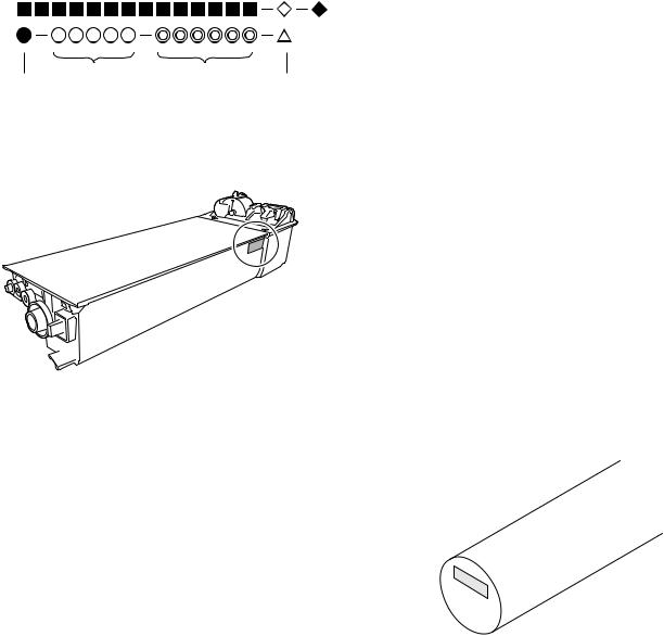
Parts marked with “ “ are important for maintaining the safety of the set.
Be sure to replace these parts with specified ones for maintaining the safety and performance of the set.
|
|
SHARP CORPORATION |
This document has been published to be used |
for after sales service only. |
The contents are subject to change without notice.

|
|
|
|
|
|
|
|
|
|
|
|
|
|
|
|
|
|
|
|
|
|
|
|
|
|
|
|
|
|
|
|
|
|
|
|
|
|
|
|
|
|
|
|
|
|
|
|
|
|
|
|
|
|
|
|
|
|
|
|
Disconnect the AC cord before servicing the unit. |
LASER WAVE - LENGTH : 785 15mm |
||||||||
|
|
|
|
|
|
Pulse times : 10.34 |
s |
0.1 |
s/7mm ; MX-M182, MX-M182D, MX-M202D |
|
|
|
|
|
|
8.665 |
s |
0.1 |
s/7mm ; MX-M232D |
|
|
|
|
|
|
Out put power : Max. 0.3mW |
|
||
|
|
|
|
|
|
|
|
|
|
CONTENTS
[1] GENERAL
1. Note for servicing . . . . . . . . . . . . . . . . . . . . . . . . . . . . . . . 1 - 1
[2] CONFIGURATION
1. System Configurations . . . . . . . . . . . . . . . . . . . . . . . . . . . 2 - 1
[3] SPECIFICATIONS
1. Copy mode . . . . . . . . . . . . . . . . . . . . . . . . . . . . . . . . . . . . 3 - 1 2. Print mode . . . . . . . . . . . . . . . . . . . . . . . . . . . . . . . . . . . . 3 - 4 3. Scanner mode . . . . . . . . . . . . . . . . . . . . . . . . . . . . . . . . . 3 - 8
[4] CONSUMABLE PARTS
1. Supply system table . . . . . . . . . . . . . . . . . . . . . . . . . . . . . 4 - 1 2. Environmental conditions . . . . . . . . . . . . . . . . . . . . . . . . . 4 - 2 3. Production number identification . . . . . . . . . . . . . . . . . . . 4 - 3
[5] EXTERNAL VIEWS AND INTERNAL STRUCTURES
1. Appearance . . . . . . . . . . . . . . . . . . . . . . . . . . . . . . . . . . . 5 - 1 2. Internal . . . . . . . . . . . . . . . . . . . . . . . . . . . . . . . . . . . . . . . 5 - 2 3. Operation Section . . . . . . . . . . . . . . . . . . . . . . . . . . . . . . . 5 - 3 4. Motor, solenoid, clutch . . . . . . . . . . . . . . . . . . . . . . . . . . . 5 - 4 5. Sensor, switch . . . . . . . . . . . . . . . . . . . . . . . . . . . . . . . . . 5 - 5 6. PWB unit. . . . . . . . . . . . . . . . . . . . . . . . . . . . . . . . . . . . . . 5 - 6 7. Cross sectional view . . . . . . . . . . . . . . . . . . . . . . . . . . . . . 5 - 7
[6] ADJUSTMENTS
1. Adjustment item list. . . . . . . . . . . . . . . . . . . . . . . . . . . . . . 6 - 1 2. Copier adjustment. . . . . . . . . . . . . . . . . . . . . . . . . . . . . . . 6 - 1
[7] SIMULATIONS
1. Entering the simulation mode . . . . . . . . . . . . . . . . . . . . . . 7 - 1 2. Canceling the simulation mode. . . . . . . . . . . . . . . . . . . . . 7 - 1 3. List of simulations . . . . . . . . . . . . . . . . . . . . . . . . . . . . . . . 7 - 1 4. Contents of simulations . . . . . . . . . . . . . . . . . . . . . . . . . . 7 - 3
[8] TROUBLE CODE LIST
1. Trouble code list . . . . . . . . . . . . . . . . . . . . . . . . . . . . . . . . 8 - 1 2. Details of trouble codes . . . . . . . . . . . . . . . . . . . . . . . . . . 8 - 1 3. Communication result code . . . . . . . . . . . . . . . . . . . . . . . 8 - 6
[9] MAINTENANCE
1. Maintenance table . . . . . . . . . . . . . . . . . . . . . . . . . . . . . . 9 - 1 2. Maintenance display system . . . . . . . . . . . . . . . . . . . . . . 9 - 2 3. Note for replacement of consumable parts . . . . . . . . . . . 9 - 2
[10] DISASSEMBLY AND ASSEMBLY |
|
1. High voltage section/Duplex transport section . . . . . . . |
.10 - 1 |
2. Optical section . . . . . . . . . . . . . . . . . . . . . . . . . . . . . . . . |
.10 - 2 |
3. Fusing section . . . . . . . . . . . . . . . . . . . . . . . . . . . . . . . |
.10 - 4 |
4. Paper exit section . . . . . . . . . . . . . . . . . . . . . . . . . . . . . |
.10 - 7 |
5. MCU . . . . . . . . . . . . . . . . . . . . . . . . . . . . . . . . . . . . . . . |
10 - 10 |
6. Optical frame unit . . . . . . . . . . . . . . . . . . . . . . . . . . . . . |
10 - 10 |
7. LSU . . . . . . . . . . . . . . . . . . . . . . . . . . . . . . . . . . . . . . . . |
10 - 10 |
8. Tray paper feed section/Paper transport section . . . . . |
10 - 11 |
9. Bypass tray section . . . . . . . . . . . . . . . . . . . . . . . . . . . |
10 - 12 |
10. Power section . . . . . . . . . . . . . . . . . . . . . . . . . . . . . . . . |
10 - 14 |
11. Developing section . . . . . . . . . . . . . . . . . . . . . . . . . . . . |
10 - 15 |
12. Process section . . . . . . . . . . . . . . . . . . . . . . . . . . . . . . . |
10 - 16 |
13. Others . . . . . . . . . . . . . . . . . . . . . . . . . . . . . . . . . . . . . . |
10 - 17 |
[11] OPERATIONAL DESCRIPTIONS
1. Paper feed operation . . . . . . . . . . . . . . . . . . . . . . . . . . . .11 - 1
[12] FLASH ROM VERSION UP PROCEDURE
1. Preparation . . . . . . . . . . . . . . . . . . . . . . . . . . . . . . . . . . .12 - 1 2. Download procedure . . . . . . . . . . . . . . . . . . . . . . . . . . . .12 - 1 3. Version confirming procedure . . . . . . . . . . . . . . . . . . . . .12 - 3 4. Facsimile Data upload procedure . . . . . . . . . . . . . . . . . .12 - 4 5. Updating the MX-NB12 firmware. . . . . . . . . . . . . . . . . . .12 - 5 6. Installation procedure . . . . . . . . . . . . . . . . . . . . . . . . . . .12 - 6
[13]IP ADDRESS SETTING
1.Setting the ip address of the machine by
system settings . . . . . . . . . . . . . . . . . . . . . . . . . . . . . . . .13 - 1
[14] ELECTRICAL SECTION
1. Block diagram . . . . . . . . . . . . . . . . . . . . . . . . . . . . . . . . .14 - 1 2. Actual wiring diagram . . . . . . . . . . . . . . . . . . . . . . . . . . .14 - 2
[1] GENERAL
1. Note for servicing
Pictogram
The label (
 ) in the fusing area of the machine indicates the following:
 : Caution, risk of danger
  : Caution, hot surface
A. Warning for servicing
•The fusing area is hot. Exercise care in this area when removing misfeed paper.
•Do not disassemble the laser unit. Do not insert a reflective material such as a screwdriver in the laser beam path.
It may damage eyes by reflection of laser beams.
B. Cautions for servicing
•Do not switch the machine rapidly on and off. After turning the machine off, wait 10 to 15 seconds before turning it back on.
•Machine power must be turned off before installing any supplies. •Place the machine on a firm, level surface.
•Do not install the machine in a humid or dusty location.
•When the machine is not used for a long time, for example, during prolonged holidays, turn the power switch off and remove the power cord from the outlet.
•When moving the machine, be sure to turn the power switch off and remove the power cord from the outlet.
•Do not cover the machine with a dust cover, cloth or plastic film while the power is on. Doing so may prevent heat dissipation, damaging the machine.
•Use of controls or adjustments or performance of procedures other than those specified herein may result in hazardous laser radiation exposure.
•The socket-outlet shall be installed near the machine and shall be easily accessible.
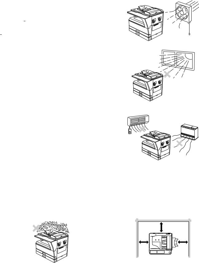
C. Note for installation place
Improper installation may damage the machine. Please note the following during initial installation and whenever the machine is moved.
Caution : If the machine is moved from a cool place to a warm place, condensation may form inside the machine. Operation in this condition will cause poor copy quality and malfunctions. Leave the machine at room temperature for at least 2 hours before use.
Do not install your machine in areas that are:
•damp, humid, or very dusty
•poorly ventilated
•exposed to direct sunlight
•subject to extreme temperature or humidity changes, e.g., near an air conditioner or heater.
The machine should be installed near an accessible power outlet for easy connection and disconnection.
Be sure to connect the power cord only to a power outlet that meets the specified voltage and current requirements. Also make certain the outlet is properly grounded.
Note : Connect the machine to a power outlet which is not used for other electric appliances. If a lighting fixture is connected to the same outlet, the light may flicker.
Be sure to allow the required space around the machine for servicing and proper ventilation.
|
20 cm (8") |
20 cm |
20 cm |
(8") |
(8") |
MX-M182 GENERAL 1-1
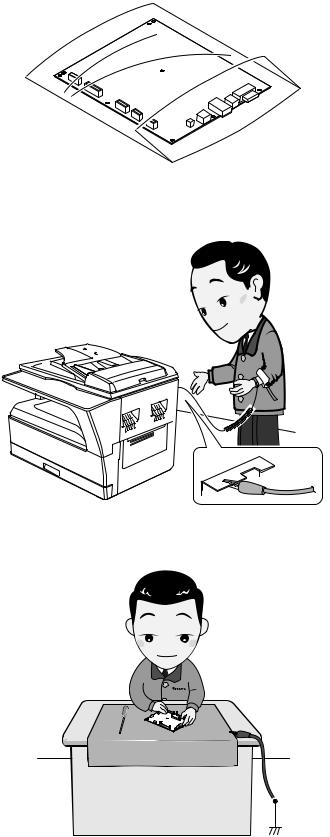
D. Note for handling PWB and electronic parts
When handling the PWB and the electronic parts, be sure to observe the following precautions in order to prevent against damage by static electricity.
1)When in transit or storing, put the parts in an anti-static bag or an anti-static case and do not touch them with bare hands.
2)When and after removing the parts from an anti-static bag (case), use an earth band as shown below:
•Put an earth band to your arm, and connect it to the machine.
3)When repairing or replacing an electronic part, perform the procedure on an anti-static mat.
MX-M182 GENERAL 1-2
[2] CONFIGURATION
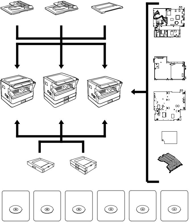
1. System Configurations
AR-RP10 AR-SP10 (MX-M182D/M202D/M232D only)
AR-VR7 (MX-M182 is standard.)
MX-NB12
MX-FX13 |
|
|
|
|
|
|
|
|
|
|
|
|
|
|
|
|
|
|
|
|
|
|
|
|
|
|
|
|
|
|
|
|
|
|
|
|
|
|
|
|
|
|
|
|
|
|
|
|
|
|
|
|
|
|
|
|
|
|
|
|
|
|
|
|
|
|
|
|
|
|
|
|
|
|
|
|
|
|
|
|
|
|
|
|
|
|
|
|
|
|
|
|
|
|
|
|
|
|
|
|
|
|
|
|
|
|
|
|
|
|
|
|
|
|
|
|
|
|
|
|
|
|
|
|
|
|
|
|
|
|
|
|
|
|
|
|
|
|
|
|
|
|
|
|
|
|
|
|
|
|
|
|
|
|
|
|
|
|
|
|
|
|
|
|
|
|
|
|
|
|
|
|
|
|
|
|
MX-M182 |
MX-M232D |
MX-M182D |
|
|
|
|
|
|
|
|
|
|
|
|
|
|
|||||
|
|
MX-M202D |
|
|
|
|
|
|
|
|
|
|
|
|
|
|
|
|
|
|
|
|
|
|
|
|
|
|
|
|
|
|
|
|
|
|
|
|
|
|
|
|
|
|
|
|
|
|
|
|
|
|
|
|
|
|
|
|
|
|
|
|
|
|
|
MX-XB17
MX-EB14
|
AR-D36 |
|
AR-D37 |
|
|
|
|
|
MX-TR10 |
|
|
|
|
|
|
|
|
|
|
||
MX-PK10 |
|
MX-USX1 |
MX-USX5 |
|
MX-US10 |
MX-US50 |
MX-USA0 |
|||
|
|
|
|
|
|
Sharpdesk 10 license kit |
|
|
|
|
PS3 EXPANSION KIT |
|
Sharpdesk 1 license kit |
Sharpdesk 5 license kit |
|
Sharpdesk 50 license kit |
Sharpdesk 100 license kit |
||||
MX-M182 CONFIGURATION 2-1

|
Model |
MX-M182 |
MX-M182D/M202D/M232D |
Option |
|
||
|
|
|
|
|
|
|
|
AR-RP10 |
Reversing single pass feeder (RSPF) |
X |
O*1 |
|
|
|
|
AR-SP10 |
Single pass feeder (SPF) |
O |
O*2 |
|
|
|
|
AR-D36 |
250-sheet paper feed unit |
O |
O |
|
|
|
|
AR-D37 |
2x250-sheet paper feed unit |
O |
O |
|
|
|
|
AR-VR7 |
DOCUMENT COVER |
STD |
O*2 |
|
|
|
|
MX-NB12 |
NETWORK EXPANSION KIT |
O |
O |
|
|
|
|
MX-FX13 |
FACSIMILE EXPANSION KIT |
O*3 |
O*3 |
|
|
|
|
MX-XB17 |
FACSIMILE MOUNTING KIT |
O |
O |
|
|
|
|
MX-TR10 |
JOB SEPARATOR |
O |
O |
|
|
|
|
MX-EB14 |
EXPANSION MEMORY BOARD |
O |
O |
|
|
|
|
MX-PK10 |
PS3 EXPANSION KIT |
O*4 |
O*4 |
|
|
|
|
MX-USX1 |
SHARPDESK 1 LICENSE KIT |
O |
O |
|
|
|
|
MX-USX5 |
SHARPDESK 5 LICENSE KIT |
O |
O |
|
|
|
|
MX-US10 |
SHARPDESK 10 LICENSE KIT |
O |
O |
|
|
|
|
MX-US50 |
SHARPDESK 50 LICENSE KIT |
O |
O |
|
|
|
|
MX-USA0 |
SHARPDESK 100 LICENSE KIT |
O |
O |
|
|
|
|
STD: Standard O: Option installation enable X: Option installation disable *1 Standard for U.S.A
*2 Not available for U.S.A
*3 MX-NB12 or MX-XB17 is required. *4 MX-NB12 is required.
MX-M182 CONFIGURATION 2-2
[3] SPECIFICATIONS
1. Copy mode
A. Type
Type |
Desk-top |
Paper exit |
center tray / internal |
B. Machine composition
MX-M182 |
18-CPM multi function model |
MX-M182D |
|
MX-M202D |
20-CPM multi function model |
MX-M232D |
23-CPM multi function model |
(1) Option
Machine |
Model |
|
250-sheet paper feed unit |
AR-D36 |
MX-M182/M182D/M202D/ |
|
|
M232D |
2x250-sheet paper feed unit |
AR-D37 |
MX-M182/M182D/M202D/ |
|
|
M232D |
SPF |
AR-SP10 |
MX-M182/M182D/M202D/ |
|
|
M232D |
RSPF*1 |
AR-RP10 |
MX-M182D/M202D/M232D |
Network expansion kit |
MX-NB12 |
MX-M182/M182D/M202D/ |
|
|
M232D |
Document cover |
AR-VR7 |
MX-M182D/M202D/M232D |
Job separator |
MX-TR10 |
MX-M182/M182D/M202D/ |
|
|
M232D |
PS3 Expantion kit |
MX-PK10 |
MX-M182/M182D/M202D/ |
|
|
M232D |
Facsimile expantion kit |
MX-FX13 |
MX-M182/M182D/M202D/ |
|
|
M232D |
Facsimile mounting kit |
MX-XB17 |
MX-M182/M182D/M202D/ |
|
|
M232D |
Expantion memory board |
MX-EB14 |
MX-M182/M182D/M202D/ |
|
|
M232D |
*1: Standard for North America and Latin America.
C. Copy speed
(1) Engine speed (ppm)
Paper size |
MX-M232D |
MX-M202D |
MX-M182 |
|
MX-M182D |
||||
|
|
|
||
A4/8.5" x 11" |
23ppm |
20ppm |
18ppm |
|
A4R/8.5" x 11"R |
15/16ppm |
14/15ppm |
14/15ppm |
|
A5/5.5"x8.5" |
23ppm |
20ppm |
18ppm |
|
B5/16K |
23ppm |
20ppm |
18ppm |
|
B5R/16KR |
18/16ppm |
16/15ppm |
16/15ppm |
|
8.5"x13" |
13ppm |
12ppm |
12ppm |
|
B4/8.5"x14" |
13ppm |
12ppm |
12ppm |
|
A3/11"x17"/8K |
12/11/12ppm |
11/10/11ppm |
11/10/11ppm |
(2) Engine performance when printing
Model |
23cpm machine |
20cpm machine |
18cpm machine |
ROPM OFF |
12ppm or more |
12ppm or more |
12ppm or more |
ROPM ON |
23ppm |
20ppm |
18ppm |
(3) Document replacement speed (Copy mode)
Copy mode |
MX-M232D |
MX-M202D |
MX-M182 |
|
MX-M182D |
||||
|
|
|
||
S to S |
20cpm (87%) |
20cpm (100%) |
18cpm (100%) |
S to S : A4/8.5" x 11" document 11 sheets, copy 1 set (Excluding the first copy)
(4) Job efficiency
Copy mode |
MX-M232D |
MX-M202D |
MX-M182 |
|
MX-M182D |
||||
|
|
|
||
S to S |
18cpm (78%) |
18cpm (90%) |
15cpm (83%) |
|
S to D |
10cpm (43%) |
10cpm (50%) |
10cpm (56%) |
|
D to D |
10cpm (43%) |
10cpm (50%) |
10cpm (56%) |
S to S : A4/8.5" x 11" document 10 sheets, copy 5 sets S to D : A4/8.5" x 11" document 10 sheets, copy 5 sets
D to D : A4/8.5" x 11" document 10 sheets (20 pages), copy 5 sets
Note : The temperature at the end portion of the heat roller may rise too high, depending on the kind of paper to be used, when in continuous printing of small-size paper.
To avoid this, when the thermistor at the end portion detects a higher temperature than the specified level, output is stopped temporarily.
During temporary stop, Power Save Indicator lamp flashes in the same manner as warming up.
(5) First copy time
Tray |
18/20cpm machine |
23cpm machine |
1st tray |
7.2 sec or less |
5.9 sec or less |
AE mode, A4/Letter, single surface copy with OC, in polygon ready state
D. Document
Max. document size |
A3, 11" x 17" |
Document reference position |
Upper left-hand corner |
Detection (Platen) |
Yes |
E. Paper feed
(1) Paper feed section details
Item |
|
1st tray |
2nd tray*1 |
Bypass tray |
|
Paper capacity |
|
250 sheets |
250 sheets |
100 sheets |
|
Paper size detection |
|
|
No |
|
|
|
|
(Paper size is set with |
|||
|
|
the operasion panel.) |
|||
Paper type setting |
|
No |
No |
No |
|
|
|
|
|
(Heavy |
|
|
|
|
|
paper setting |
|
|
|
|
|
is enabled.) |
|
Paper size changing method |
The paper guide is set by the user. |
||||
Default paper size |
AB series |
A4 |
A4 |
- |
|
when shipping |
|
|
|
|
|
Inch series |
8 1/2" x11" |
8 1/2" x11" |
- |
||
|
|||||
Remaining paper quantity |
Only empty detection available |
||||
detection |
|
|
|
|
|
*1: 2-stage standard only for the MX-M202D/M232D |
|
||||
MX-M182 SPECIFICATIONS 3-1

(2) Feedable paper
Paper size |
|
1st tray |
2nd tray |
Bypass |
|
|
|
|
tray |
A3 |
297x420 |
Yes |
Yes |
Yes |
B4 |
257x364 |
Yes |
Yes |
Yes |
A4 |
297x210 |
Yes |
Yes |
Yes |
A4-R |
210x297 |
Yes |
Yes |
Yes |
B5 |
257x182 |
Yes |
Yes |
Yes |
B5R |
182x257 |
Yes |
Yes |
Yes |
A5 |
210x148.5 |
Yes |
N/A |
Yes |
A5R |
148.5x210 |
N/A |
N/A |
Yes |
A6R |
105x148.5 |
N/A |
N/A |
Yes |
B6R |
128.5x182 |
N/A |
N/A |
Yes |
Ledger 11x17 in |
279.4x431.8 |
Yes |
Yes |
Yes |
Legal 8.5x14in. |
215.9x355.6 |
Yes |
Yes |
Yes |
8.5x13.4 *1 |
216x340 *1 |
*1 |
*1 |
*1 |
Foolscap 8.5x13 in |
215.9x330.2 |
Yes |
Yes |
Yes |
Letter 11x8.5in |
279.4x215.9 |
Yes |
Yes |
Yes |
Letter-R 8.5x11in |
215.9x279.4 |
Yes |
Yes |
Yes |
Executive-R 7.25x10.5in. |
184.2x266.7 |
N/A |
N/A |
Yes |
Invoice 8.5x5.5 in. |
215.9x139.7 |
Yes |
N/A |
Yes |
Invoice-R 5.5x8.5 in |
139.7x215.9 |
N/A |
N/A |
Yes |
8K |
270x390 |
Yes |
Yes |
Yes |
16K |
270x195 |
Yes |
Yes |
Yes |
16KR |
195x270 |
Yes |
Yes |
Yes |
COM10 |
104.8x241.3 |
N/A |
N/A |
Yes |
*1: Switches by SIM26-2. (Operation UI supports by 8.5x13 and exclusion.)
(3)Types of feedable paper
Types of paper |
1st tray |
2nd tray |
Bypass tray |
|
Thin paper |
56-59g/m2 |
Yes |
Yes |
Yes |
|
15-15.9lbs |
|
|
|
Plain paper |
60-90g/m2 |
Yes |
Yes |
Yes |
|
16-24lbs |
|
|
|
Heavy paper |
91-105g/m2 |
N/A |
N/A |
Yes |
|
16-24lbs |
|
|
(Multi paper feed enable) |
Heavy paper |
106-128g/m2 |
N/A |
N/A |
Yes |
|
24.1-33.5lbs |
|
|
(A4 or less) |
|
|
|
|
(Multi paper feed enable) |
Heavy paper |
129-200g/m2 |
N/A |
N/A |
Yes |
|
33.6-53.2lbs |
|
|
(A4 or less) |
|
|
|
|
(Only single paper feed) |
Heavy paper |
201-256g/m2 |
N/A |
N/A |
N/A |
|
53.3-68lbs |
|
|
|
Envelope |
75-90g/m2 |
N/A |
N/A |
Yes |
|
20-24lbs |
|
|
|
Postcard |
|
N/A |
N/A |
Yes |
OHP film |
|
N/A |
N/A |
Yes |
Label sheet |
|
N/A |
N/A |
Yes |
Tab paper 20 |
|
N/A |
N/A |
N/A |
F. Multi copy
Max. number of multi copy |
999 sheets |
G. Warm-up time
Warm-up time |
25 seconds or less |
Pre-heat |
Available |
Jam recovery |
Within 25 sec |
H. Copy magnification ratio
Fixed magnification |
AB system: |
|
ratio |
400, 200, 141, 122, 115, 100, 86, 81, 70, 50, 25% |
|
|
|
Inch system: |
|
|
400, 200, 141, 129, 121, 100, 95, 77, 64, 50, 25% |
Zooming |
25 ~ 400% |
|
|
|
SPF/RSPF (50 ~ 200%) |
Independent |
Available (25 ~ 400%) |
|
zooming (vertical) |
SPF/RSPF (50 ~ 200%) |
|
Independent |
Available (25 ~ 400%) |
|
zooming (horizontal) |
SPF/RSPF (50 ~ 200%) |
|
I. Copy density
Density mode |
Auto / Text / Photo |
|
|
|||
No. of manual |
5 steps (Text / Photo) |
|
|
|||
adjustment |
|
|
|
|
|
|
Resolution |
|
Writing: 600 x 600dpi |
|
|
||
|
|
Reading: 400 (main) x 600 (sub) (PHOTO mode) |
|
|||
|
|
|
400 (main) x 600 (sub) (AUTO exposure |
|||
|
|
|
mode) |
|
|
|
|
|
|
400 (main) x 600 (sub) dpi (TEXT mode) |
|
||
Gradation |
|
Reading: 256 gradations |
|
|
||
|
|
Writing: Binary |
|
|
||
J. Void width |
|
|
|
|
|
|
|
|
|
|
|||
Void area |
Lead edge 1 ~ 4mm |
|
|
|||
|
Rear edge 4mm or less |
|
|
|||
|
Total of both sides: 6mm or less |
|
|
|||
Image loss |
OC |
|
|
Same size |
3mm or less |
|
|
SPF/RSPF |
|
Same size |
4mm or less |
|
|
K. Auto duplex
Standard/ |
Standard provision (MX-M182D/M202D/M232D only) |
Option |
(D D / D S enable only when RSPF is installed) |
|
Not available for MX-M182 |
L. Paper exit / finishing
Paper exit section |
Face down 250 sheets |
capacity |
|
Full detection |
Upper stage: Yes (Job separator is installed) |
|
Lower stage: No (Copy/printer 250 sheets |
|
count detection) |
Finishing |
None |
Electronic sort |
A4/ 8.5" x 11" standard document |
capacity |
(6% coverage) 160 sheets |
Offset function |
Yes |
Staple function |
None |
MX-M182 SPECIFICATIONS 3-2
M. Additional functions
|
|
MX-M182 |
|
MX-M182D/M202D/ |
|
|
|
M232D |
|
|
|
|
|
|
APS |
|
|
O |
|
AMS |
|
|
O |
|
Auto tray switching |
|
O |
||
Memory copy |
|
|
O |
|
Rotation copy |
|
|
O |
|
E-sort |
|
|
O |
|
(Sorting function) |
|
|
||
|
|
|
|
|
E-sort |
|
|
O |
|
(Grouping function) |
|
|||
|
|
|
||
Rotation sort |
|
|
X |
|
Prevention of sky shot |
|
X |
||
Independent zooming |
|
O |
||
1 set 2 copy |
|
O |
|
O |
|
|
SPF: Disable |
|
SPF/RSPF: Disable |
|
|
OC: Enlargement is |
|
OC: Enlargement is |
|
|
disable. |
|
disable. |
Binding margin |
|
|
O |
|
Edge erase |
|
Default AB series: 10mm |
||
Center erase |
|
(5, 10, 15, 20mm) |
|
|
|
|
Inch series: 1/2 inch |
|
|
|
|
(1/4, 1/2, 3/4, 1 inch) |
|
|
Black/white reverse |
|
X |
||
2in1/4in1 |
|
|
O |
|
Offset |
|
|
O |
|
Preheating |
|
|
O |
|
|
|
The conditions are set by the system setting. |
||
Auto shut-off |
|
|
O |
|
|
|
The conditions are set by the system setting. |
||
System setting |
|
|
O |
|
Counter |
|
|
O |
|
|
|
(1) Copy total |
|
|
|
|
(2) Print total |
|
|
|
|
(3) Scan |
|
|
|
|
(4) Toner residual quantity |
||
Coin vendor support |
|
O |
||
|
|
(Supporting the interface only) |
||
Auditor support |
|
|
O |
|
|
|
(Supporting the interface only) |
||
Duplex |
|
X |
|
O |
Toner save |
|
|
O |
|
|
|
(Set according to the destination) |
||
Account control |
|
|
O |
|
|
|
(Copy/Printer/Scanner Number of control: 50) |
||
O : Available X |
: Not available |
|
|
|
N. Other specifications
Photoconductor type |
OPC (Organic Photo Conductor) |
Photoconductor drum dia. |
30mm |
Copy lamp |
WhiteCCFL |
Developing system |
Dry 2-component magnetic brush |
|
development |
Charging system |
Saw teeth charging |
Transfer system |
(+) DC corotron |
Separation system |
(-) DC corotron |
Fusing system |
Heat roller |
Cleaning system |
Contact blade |
O. Package form
Body |
Body / Accessories |
P. External view
|
Standard model |
D model |
External dimensions |
591mm(W) x 573mm(D) |
|
(With the bypass tray closed) |
|
|
Occupying area |
883mm(W) x 573mm(D) |
|
(With the bypass tray opened) |
|
|
Weight |
1-tray model: |
1-tray model: |
(Excluding developer) |
29.4kg |
29.6kg (OC) |
|
|
2-tray model: |
|
|
35.0kg (OC) |
|
|
1-tray model: |
|
|
33.2kg (RSPF) |
|
|
2-tray model: |
|
|
38.6kg (RSPF) |
Q. Power source
Voltage |
100 - 127V 220 - 240V |
Frequency |
50/60Hz common |
R. Power consumption
Max. power consumption |
1200W |
S. Digital performance
Resolution |
Reading |
400 x 600dpi (PHOTO mode) |
|
|
400 x 600dpi (AUTO exposure mode) |
|
|
400 (main) x 600 (sub) dpi (TEXT mode) |
|
Writing |
600 x 600dpi |
Gradation |
Reading |
256 gradations |
|
Writing |
Binary |
Memory (MAX) |
256MB (with MX-EB14) |
|
Hard disk |
None |
|
MX-M182 SPECIFICATIONS 3-3
2. Print mode
A. Printing function
(1) Platform
|
Item |
|
|
Content |
|
|
|
|
|
|
|
||
Support platform |
|
IBM PC/AT compatible machine |
|
|
|
|
|
|
|||||
(2) Support OS |
|
|
|
|
|
|
|
|
|
|
|||
|
|
|
|
|
|
|
|
|
|
|
|
|
|
|
|
|
|
|
Main unit |
|
|
When MX-NB12 is installed |
|
When MX-FX13 is |
|||
|
|
|
|
|
|
|
|
installed |
|||||
|
|
OS |
|
|
|
|
|
|
|
|
|
||
|
|
|
Twain/Button |
|
SPLC |
Custom |
Custom |
Custom |
PPD |
PC-FAX |
|||
|
|
|
|
|
|
||||||||
|
|
|
|
|
Manager |
|
PCL6 |
PCL5e |
PS |
||||
|
|
|
|
|
|
|
|
|
|||||
Windows |
|
98/Me |
|
No |
|
No |
|
No |
No |
No |
No |
No |
|
|
|
NT 4.0 SP5 or later |
No |
|
No |
|
No |
No |
No |
No |
No |
||
|
|
2000 |
|
|
CD-ROM |
|
CD-ROM |
CD-ROM |
No |
CD-ROM |
CD-ROM |
CD-ROM |
|
|
|
XP |
|
CD-ROM |
|
CD-ROM |
CD-ROM |
No |
CD-ROM |
CD-ROM |
CD-ROM |
||
|
|
XPx64 |
|
CD-ROM |
|
CD-ROM |
CD-ROM |
No |
CD-ROM |
CD-ROM |
CD-ROM |
||
|
|
Server 2003 |
|
No |
|
No |
CD-ROM |
No |
CD-ROM |
CD-ROM |
CD-ROM |
||
|
|
Server 2003x64 |
|
No |
|
No |
CD-ROM |
No |
CD-ROM |
CD-ROM |
CD-ROM |
||
|
|
Vista |
|
CD-ROM |
|
CD-ROM |
CD-ROM |
No |
CD-ROM |
CD-ROM |
CD-ROM |
||
|
|
Vistax64 |
|
CD-ROM |
|
CD-ROM |
CD-ROM |
No |
CD-ROM |
CD-ROM |
CD-ROM |
||
|
|
Server 2008 |
|
No |
|
No |
CD-ROM |
No |
CD-ROM |
CD-ROM |
CD-ROM |
||
|
|
Server 2008x64 |
|
No |
|
No |
CD-ROM |
No |
CD-ROM |
CD-ROM |
CD-ROM |
||
|
|
Windows 7 |
|
CD-ROM |
|
CD-ROM |
CD-ROM |
No |
CD-ROM |
CD-ROM |
CD-ROM |
||
|
|
Windows 7x64 |
|
CD-ROM |
|
CD-ROM |
CD-ROM |
No |
CD-ROM |
CD-ROM |
CD-ROM |
||
Mac |
|
9.0-9.2.2 |
|
|
No |
|
No |
|
No |
No |
No |
No |
No |
|
|
X 10.2.8 |
|
No |
|
No |
|
No |
No |
No |
Web |
No |
|
|
|
X 10.3.9 |
|
No |
|
No |
|
No |
No |
No |
Web |
No |
|
|
|
X 10.4.11 |
|
No |
|
No |
|
No |
No |
No |
CD-ROM |
No |
|
|
|
X 10.5- 10.5.8 |
|
No |
|
No |
|
No |
No |
No |
CD-ROM |
No |
|
|
|
X 10.6-10.6.4 |
|
No |
|
No |
|
No |
No |
No |
CD-ROM |
No |
|
(3) Printer driver function
a. Windows version of SPLC driver
|
Function |
Overseas |
Description |
Main |
Copies |
1-999 |
Perform specified numbers of printing. |
|
Collate |
Collate |
If "Collate" is specified, plural printing by the number of set is done, |
|
|
Uncollate |
and "Uncollate" is specified, plural printing by page is done. |
|
Document Style |
1-sided |
Simplex or duplex printing is done depending on the setting. |
|
|
2-sided (Book) |
Print direction is different depending on book/tablet for duplex |
|
|
2-sided (Tablet) |
printing. (* Simplex model have no duplex function.) |
|
N-up |
2/4/6 |
Specified numbers of pages are printed on one sheet. |
|
N-up Order |
Z |
|
|
N-up Border |
Yes / No |
Partition line is added for the plural pages printed on 1 sheet. |
|
User Setting |
Add/Delete |
Register the setting value for commonly-used driver. |
|
Image Orientation |
Portrait |
Print in the specified print direction. |
|
|
Landscape |
|
|
Rotate 180 Degree |
Yes / No |
Rotate data 180 degrees to print. |
Paper |
Paper Size (paper size) |
A3 / B4 / A4 / B5 / A5 / A6 / B6 / Ledger / |
Print in the specified paper size. Even if actual paper size is different |
|
|
Legal/ 8.5x13.4 / Foolscap / Folio / Letter / |
from the specified paper size, the image is created in the specified |
|
|
Invoice / Executive / 8K / 16K / COM-10 / |
paper size to print. |
|
|
DL / C5 / A2(Fit To Page) / Custom *1 |
|
|
Custom Paper Size |
1 size |
Width: 100 - 297mm |
|
(paper size) |
|
Length: 148 - 431.8mm |
|
Fit to Page |
Yes/No |
Print size is changed according to the specified contents. |
|
(Zoom setting) |
|
|
|
Zoom (Zoom setting) |
25-400% |
|
|
Fit to Page size |
A3 / B4 / A4 / B5 / A5 / A6 / B6 / Ledger / |
|
|
(Zoom setting) |
Legal / 8.5x13.4/ Foolscap / Folio / Letter / |
|
|
|
Invoice / Executive / 8K / 16K / COM-10 / |
|
|
|
DL / C5 |
|
|
Paper Selection |
Auto |
Paper is fed from the specified paper feed tray. |
|
|
Bypass (Auto) |
|
|
|
Bypass (Manual) |
|
|
|
Tray 1/2 (3/4) |
|
|
Output |
Center Tray / Upper Tray |
|
MX-M182 SPECIFICATIONS 3-4
|
Function |
Overseas |
Description |
Advanced |
Brightness |
0 - 100% |
Adjust the brightness of the image by moving the scale within the |
|
(Image adjustment) |
|
range of 0-100. The illustration image at the upper left of the screen |
|
|
|
changes by this adjustment. |
|
Contrast |
0 - 100%. |
Adjust the contrast of the image by moving the scale within the range |
|
(Image adjustment) |
|
of 0-100. The illustration image at the upper left of the screen |
|
|
|
changes by this adjustment |
|
Text To Black |
Yes / No |
Print documents created by CAD software in B/W to improve |
|
|
|
visualization of colored line image/text. |
|
Vector To Black |
Yes / No |
Print lines in BW to improve visualization. |
|
Input Resolution |
600dpi/300dpi |
Select input resolution (default: 600dpi) |
|
(compatibility) |
|
|
|
Hatching Pattern |
Standard/fine |
Select hatching pattern (default: standard) |
|
(compatibility) |
|
|
|
Spool format |
RAW/EMF |
Default: RAW |
|
(compatibility) |
|
|
|
Reduction Method |
Standard/By Object/ By page |
Default: Standard |
|
(compatibility) |
|
|
|
Print density |
1 - 5 stages |
Default: 3 |
|
(compatibility) |
|
|
|
Duplex print |
Yes / No |
Specify duplex printing function with giving priority to driver. |
|
(Compatibility) |
|
|
|
Duplex Style |
Pattern1/ Pattern2/ Pattern3 |
Default: 1 |
|
(compatibility) |
|
|
|
Print by number of copy |
Yes / No |
Specify print by set function with giving priority to driver. |
|
(compatibility) |
|
|
Water |
Watermark |
None / TOP SECRET / CONFIDENTIAL / |
Select watermark specified as default. |
marks |
|
DRAFT / ORIGINAL / COPY |
|
|
User Setting |
Add / Update / Delete |
Add, register and delete watermark. |
|
Position |
Center |
Adjust the position of watermark vertically and horizontally. |
|
|
X: ±50 |
|
|
|
Y: ±50 |
|
|
Size |
6 - 300 |
Adjust the size of watermark. |
|
Angle |
±90 |
Adjust the angle of watermark. |
|
Grayscale |
0 - 255 |
Adjust the watermark density. |
|
Edit Font |
Yes |
Edit font. |
|
Thick Letter |
Yes/No |
|
|
Italic Face |
Yes/No |
|
|
Character Set |
Yes |
|
|
On First Page only |
Yes / No |
Put watermark only on the first page. |
Option |
ROPM |
On/Off |
|
|
Paper Feed Option |
1-Tray/2-Tray/3-Tray/4-Tray |
|
|
Auto Configuration |
Yes |
|
|
Paper Tray (Tray Setting) |
Bypass Tray/Tray1/Tray2/Tray3/Tray4 |
|
|
Paper Size to Specify |
No specification/ A3 / B4 / A4 / B5 / A5 / |
|
|
|
A6 / B6 / Ledger / Legal / 8.5x13.4 / |
|
|
|
Foolscap / Folio / Letter / Invoice / |
|
|
|
Executive / 8K / 16K / COM-10 / DL / C5 / |
|
|
|
Custom |
|
|
Status Window |
Yes |
|
|
Version Information |
Yes |
|
*1: Custom paper size range: Width 100 - 297.0 mm (3.94 -11.69 inch) Length 148 -431.8mm (5.83 - 17.00 inch)
MX-M182 SPECIFICATIONS 3-5
b. Windows version of PCL/PS Driver (PCL: MX-NB12 is expanded)
|
|
Function |
PCL6 |
PS |
Main |
Copies |
|
1-999 |
1-999 |
|
Image |
|
Portrait |
Portrait |
|
Orientation |
|
Landscape |
Landscape |
|
|
Rotate 180 Degree |
Yes / No |
Yes / No |
|
Collate |
|
Collate |
Collate |
|
|
|
Uncollate |
Uncollate |
|
Document Style |
1-Sided, 2-Sided(Book) 2-Sided(Tablet), |
1-Sided, 2-Sided(Book) 2-Sided(Tablet), |
|
|
|
|
Pamphlet Style (Tiled Pamphlet), |
Pamphlet Style (Tiled Pamphlet), |
|
|
|
Pamphlet Style (2-up Pamphlet) |
Pamphlet Style (2-up Pamphlet) |
|
Job Control |
Inform job end |
Yes/No |
Yes/No |
|
|
Account Number Setting |
Yes/No (5 digits) |
Yes/No (5 digits) |
|
|
Confirm Job Control |
Yes/No |
Yes/No |
|
Binding Edge |
|
N/A |
N/A |
|
Margin Shift |
|
N/A |
N/A |
|
N-up |
N-up |
2/4/6/8/9/16 |
2/4/6/8/9/16 |
|
|
N-up Order |
Z |
Z |
|
|
N-up Border |
Yes/No |
Yes/No |
Paper |
Paper Size |
Paper Size |
A3 / B4 / A4 / B5 / A5 / B6 / A6 / 11x17 / |
A3 / B4 / A4 / B5 / A5 / B6 / A6 / 11x17 / |
|
|
|
8.5x14 / 8.5 x 13.4/ 8.5x13 / 8.5x11 / 5.5x8.5 / |
8.5x14 / 8.5 x 13.4/ 8.5x13 / 8.5x11 / 5.5x8.5 / |
|
|
|
Folio / Executive / COM-10 / DL / C5/ 8K / |
Folio / Executive / COM-10 / DL / C5 / 8K / |
|
|
|
16K / A0 (Fit To Page) / A1(Fit To Page)/ |
16K / Custom *1 |
|
|
|
A2(Fit To Page) / Custom *1 |
|
|
|
Paper Type |
N/A |
N/A |
|
|
Custom Paper Size |
1 size |
1 size |
|
Zoom Setting |
Fit to Page |
Yes/No |
Yes/No |
|
|
Zoom |
25-400% |
N/A |
|
|
|
Reference Point: Upper left/Center |
|
|
|
XY-Zoom |
N/A |
Width: 25 - 400% |
|
|
|
|
Length: 25 - 400% |
|
|
|
|
Lock Aspect Ratio: On/Off |
|
|
|
|
Reference Point: Upper left/Center |
|
|
Fit to Page size |
A3 / B4 / A4 / B5 / A5 / B6 / A6 / 11x17 / |
A3 / B4 / A4 / B5 / A5 / B6 / A6 / 11x17 / |
|
|
|
8.5x14 / 8.5 x 13.4 / 8.5x13 / 8.5x11 / |
8.5x14 / 8.5 x 13.4 / 8.5x13 / 8.5x11 / |
|
|
|
5.5x8.5 / Folio / Executive / COM-10 / DL / |
5.5x8.5 / Folio / Executive / COM-10 / DL / |
|
|
|
C5 / 8K / 16K |
C5 / 8K / 16K |
|
Paper Selection |
Auto |
Auto |
|
|
|
|
Bypass (Auto) |
Auto Bypass (Auto) |
|
|
|
Bypass (Manual) |
Bypass (Manual) |
|
|
|
Tray 1/2/3/4 |
Tray 1/2/3/4 |
Advanced |
Graphics mode |
Raster/Vector |
N/A |
|
|
Mirror Image |
|
N/A |
Horizontal Vertical |
|
PostScript |
PS Error Information |
N/A |
Yes/No |
|
Option |
PS Pass-Through |
N/A |
Yes/No |
|
Bitmap Compression |
None / Very High Quality / High Quality / |
N/A |
|
|
|
|
Medium Quality / Draft |
|
|
Compression |
Job Compression |
N/A |
None / Fastest / Fast / Medium / |
|
Options |
|
|
Best Compression |
|
|
Bitmap Compression |
N/A |
None / Very High Quality / High Quality / |
|
|
|
|
Medium Quality / Draft |
|
Compatibility |
Input Resolution |
600/300 dpi |
N/A |
|
|
Halftone Setting |
N/A |
N/A |
|
|
Hatching Pattern |
Standard/Fine |
N/A |
|
|
Spool Format |
RAW/EMF |
N/A |
|
|
Print Density |
1-5 Stages |
1-5 Stages |
|
|
Print by set (Give priority |
Yes / No |
N/A |
|
|
to Driver Setting) |
|
|
|
|
Duplex Printing (Give |
Yes / No |
N/A |
|
|
Priority to Driver Setting) |
|
|
|
|
Negative Image |
N/A |
N/A |
|
|
Mirror Image |
N/A |
N/A |
|
|
Zoom |
N/A |
N/A |
|
|
Duplex Style |
Pattern1/ Pattern2/ Pattern3 |
Pattern1 / Pattern2 / Pattern3 |
|
Overlay |
|
ON/OFF |
ON/OFF |
|
Font Setting |
|
Yes |
Yes |
|
|
|
Resident Font: 80 fonts |
Resident Font: 80 fonts |
MX-M182 SPECIFICATIONS 3-6
|
|
Function |
PCL6 |
PS |
Advanced |
Image |
Brightness |
0 - 100% |
0 - 100% |
|
Adjustment |
Contrast |
0 - 100% |
0 - 100% |
|
Text To Black |
|
Yes / No |
Yes / No |
|
Vector To Black |
Yes / No |
Yes / No |
|
|
Right binding |
|
Yes/No |
Yes / No |
Water marks |
Watermark |
|
None / TOP SECRET / CONFIDENTIAL / |
None / TOP SECRET / CONFIDENTIAL / |
|
|
|
DRAFT / ORIGINAL / COPY |
DRAFT / ORIGINAL / COPY |
|
User Setting |
|
Add / Update / Delete |
Add / Update / Delete |
|
Position |
|
Center |
Center |
|
|
|
X: ±50 |
X: ±50 |
|
|
|
Y : ±50 |
Y : ±50 |
|
Size |
|
6 - 300 |
6 - 300 |
|
Angle |
|
±90 |
±90 |
|
Grayscale |
|
0 - 255 |
0 - 255 |
|
Edit Font |
|
Yes |
Yes |
|
Thick Letter |
|
Yes/No |
Yes/No |
|
Italic Face |
|
Yes/No |
Yes/No |
|
Character Set |
|
Yes |
Yes |
|
Print Pattern |
|
Transparent 1 / Transparent 2 / Overlap / |
Transparent / Overlap / Outline |
|
|
|
Outline |
|
|
Frame Line |
|
None/rectangle/Circle |
None/rectangle/Circle |
|
On First Page only |
Yes / No |
Yes / No |
|
Special Mode |
Page Interleave |
Yes |
N/A |
|
|
Paper |
Different 1st (Cover) and |
1st Page: On/Off |
1st Page : On/Off |
|
Insertion |
Last Page |
(Last Page Not Support) |
(Last Page Not Support) |
|
Setting |
Duplex Printing |
Yes/No |
Yes/No |
|
|
Paper Tray |
Bypass (Auto) |
Bypass (Auto) |
|
|
|
Bypass(Manual) |
Bypass(Manual) |
|
|
|
Tray 1/2/3/4 |
Tray 1/2/3/4 |
|
|
Transparency Inserts |
N/A |
N/A |
|
|
Carbon Copy |
N/A |
N/A |
Option |
ROPM |
|
On/Off |
On/Off |
|
Paper Feed Option |
1-Tray/2-Tray/3-Tray/4-Tray |
1-Tray/2-Tray/3-Tray/4-Tray |
|
|
Job Separator |
|
On/Off |
On/Off |
|
Option Auto Setting |
Yes |
Yes |
|
|
Tray Setting |
Paper Tray |
Bypass Tray/ Tray1/Tray2/Tray3/Tray4 |
Bypass Tray/ Tray1/Tray2/Tray3/Tray4 |
|
|
Paper Size to Specify |
Not Specified/ A3 / B4 / A4 / B5 / A5 / A6 / |
Not Specified/ A3 / B4 / A4 / B5 / A5 / A6 / |
|
|
|
B6 / Ledger / Legal / 8.5x13.4 / Foolscap / |
B6 / Ledger / Legal / 8.5x13.4 / Foolscap / |
|
|
|
Folio / Letter / Invoice / Executive / 8K / 16K / |
Folio / Letter / Invoice / Executive / 8K / 16K / |
|
|
|
COM-10 / DL / C5 / Custom) |
COM-10 / DL / C5 / Custom) |
|
Print Policy |
|
Yes |
Yes |
|
Font |
|
N/A |
Yes |
|
Version Information |
Yes |
Yes |
|
*1: Custom paper size range: Width 100 - 297.0 mm (3.94 -11.69 inch) Length 148 -431.8mm (5.83 - 17.00 inch)
MX-M182 SPECIFICATIONS 3-7
C. Windows version/Mac version of PPD Driver
Function |
WinPPD |
Mac PPD |
Copies |
Yes |
Yes |
Collate/Uncollate |
Yes |
Yes |
N-UP |
Yes |
Yes |
N-up Order |
No |
Yes |
N-up Border |
No |
Yes |
Duplex |
Yes |
Yes |
Retention |
No |
No |
Document Filling |
No |
No |
User Authentication |
No |
No |
User Number |
No |
Yes |
Job ID (User Name/ |
No |
Yes |
Job Name) |
|
|
Color Mode |
No |
No |
Print Mode |
No |
No |
Image Type |
No |
No |
Neutral Gray |
No |
No |
Pure Black Print |
No |
No |
Black Over Print |
No |
No |
Toner Save |
No |
No |
Color Adjustment |
No |
No |
Source Profile |
No |
No |
Rendering Intent |
No |
No |
Output Profile |
No |
No |
Screening |
No |
No |
Simulation Profile |
No |
No |
Paper Size |
A3 / B4 / A4 / B5 / A5 / |
A3 / B4 / A4 / B5 / A5 / |
|
B6 / A6 / 11x17 / |
B6 / A6 / 11x17 / |
|
8.5x14 / 8.5 x 13.4/ |
8.5x14 / 8.5 x 13.4/ |
|
8.5x13 / 8.5x11 / |
8.5x13 / 8.5x11 / |
|
5.5x8.5 / Folio / |
5.5x8.5 / Folio / |
|
Executive / COM-10 / |
Executive / COM-10 / |
|
DL / C5/ 8K / 16K/ |
DL / C5 / 8K / 16K / |
|
Custom*1 |
A0 (Fit To Page) / A1 (Fit |
|
|
To Page) / A2 (Fit To |
|
|
Page) / Custom*1 |
Output Tray |
Upper Tray Center Tray |
Upper Tray Center Tray |
*1: Custom paper size range: Width 100 - 297.0 mm (3.94 -11.69 inch) Length 148 -431.8mm (5.83 - 17.00 inch)
3. Scanner mode
A. Scanner function
(1) Mode
Mode |
Sub Mode |
|
Scanner |
Yes |
|
|
FTP Server |
(MX-NB12 is expanded) |
|
Network Folder (SMB) |
No |
|
Desktop |
Yes |
|
USB Memory |
(MX-NB12 is expanded) |
Twain Scan |
– |
Yes |
(Including Button |
|
|
Manager) |
|
|
(2) Support Image (MX-NB12 is expanded)
Mode |
Mode |
Type |
Support |
Scanner |
File Format |
TIFF |
Yes |
(MX-NB12 is |
(B/W) |
Yes |
|
expanded) |
|
PDF/A |
N/A |
|
|
Encrypted PDF |
N/A |
|
|
XPS |
N/A |
|
File Format |
TIFF |
Yes |
|
(Gray Scale) |
JPEG |
Yes |
|
|
Yes |
|
|
|
PDF/A |
N/A |
|
|
Encrypted PDF |
N/A |
|
|
Compact PDF (ACRE installed) |
N/A |
|
|
XPS |
N/A |
|
File Format |
TIFF |
Yes |
|
(Color) |
JPEG |
Yes |
|
|
Yes |
|
|
|
PDF/A |
N/A |
|
|
Encrypted PDF |
N/A |
|
|
Compact PDF (ACRE installed) |
N/A |
|
|
XPS |
N/A |
(3) Image Processing
Mode |
|
Scanner (MX-NB12 is expanded) |
Exposure Adjustment |
Auto |
Yes |
|
Manual |
5 levels |
Original Type *1 |
Text |
Yes |
|
Photo |
Yes |
|
Auto |
Yes |
Resolution (Different depending on |
75 x 75 dpi |
|
file format/ sending method) |
100x100dpi |
|
|
|
150x150dpi |
|
|
200x200dpi |
|
|
300x300dpi |
|
|
400x400dpi |
|
|
600x600dpi |
*1: This setting can only be set at the B/W mode
(4) Push Scan (Button Manager)
Support OS |
Windows 2000 Professional/Windows XP Home Edition/ |
|
|
Windows XP Professional/Windows Vista/Windows 7 |
|
Hardware |
(System) |
Shall meet the operating conditions of each OS |
Environment |
|
basically. |
|
(HDD) |
8MB or more: 100MB or more is recommended |
|
(Monitor) |
800x600 dots or more |
|
|
Shall be able to display 256 colors or more. |
|
(Other) |
USB port (2.0) |
Selectable |
Sharpdesk/ E-mail software/ Fax software/ OCR |
|
destination |
software/ MS Word/ Any directory |
|
File Format |
TIFF/PDF/BMP |
|
MX-M182 SPECIFICATIONS 3-8
(5) Pull Scan (TWAIN)
|
USB TWAIN (Does not function in Network system) |
Support OS |
Windows 2000 Professional/Windows XP Home Edition/ Windows XP Professional/ Windows Vista/Windows 7 |
Interface |
USB |
Hardware Environment |
(System) Shall meet the operating conditions of each OS basically. |
|
(HDD) 8MB or more: 100MB or more is recommended |
|
(Monitor) 800x600dots or more |
|
Shall be able to display 256 colors or more. |
|
(Other) USB port |
Two-sided Scan |
Yes |
Color Mode |
B/W(Mono2)/ B/W(Error Diffusion)/Gray Scale/Full Color |
Resolution |
75dpi/ 100dpi/ 150dpi/ 200dpi/ 300dpi/ 400dpi/ 600dpi Or Custom: 50 - 9600dpi (simulated) |
Scanning Range |
A3/ A4/ A4-R/ A5/ A5-R/ B4/ B5/ B5-R/ Ledger/ Letter/ Letter-R/ Executive/ Executive-R/ Foolscap/ Invoice/ |
|
Invoice-R/ Legal/ 8.5x13.4/ 8.5x13.5(343x216mm)/ Postcard/ 8K/ 16K/ 16K-R/ Auto/ User Definition |
Preview Function |
Yes |
Zoom Preview Function |
Yes |
Rotation Scan |
Yes (90 / 180/ 270 degrees) |
Quick Scan |
No |
Brightness/Contrast Adjustment |
Auto/ Manual(-100 - +100) |
Gamma Adjustment |
Yes |
Color Matching |
None/ Printer/ CRT/ LCD display/ ICM |
Edge Emphasis |
None/ Normal/ High/ Fuzzy |
B/W Reverse |
Yes |
Selection of Light Source Color |
Yes (Red/ Green/ Blue/ White) |
Threshold Setting |
Auto/ Manual (1-254) |
Addition of Void Area |
Available (Lead Edge/Trail Edge: 2.5mm Right/Left: 3.0mm) |
Storing of Setting Contents |
Yes |
Keeping of Preview Image |
Yes |
Unit of Display for Scanning Range |
Pixel/ mm/ inch |
Notes' Security Feature |
No |
(6) Network Push Scan (MX-NB12 is expanded) a. Specification
Support OS |
Windows 2000 Professional/Windows XP Home Edition/ Windows XP Professional/Windows Vista/Windows 7 |
Scan Resolution |
75x75, 100x100, 150x150, 200x200, 300x300, 400x400, 600x600dpi (main direction x sub direction) |
Interface |
USB 2.0, 10/100BASE-TX |
Support Server/Protocol |
TCP/IP, SMTP, LDAP, FTP |
Output file format |
B&W : PDF (w/o compression, G3, G4), TIFF (w/o compression, G3, G4) |
|
Color/Gray scale: JPEG, PDF(JPEG), TIFF(JPEG) |
|
TIFF/PDF supports multi page. |
2-sided original scan |
Yes |
Optical Resolution |
400x600dpi |
File creation |
File per 1 to 6 page / 1 file for all pages |
Sending method/Linkage |
File server sending scan |
|
Desktop sending scan |
|
E-mail sending scan |
|
USB memory scan |
Density |
1 - 5 |
Light Source |
Yes (Red/ Green/ Blue/ White) |
Void Area |
Yes |
Control System |
Embedded Web server |
Recommended Web browser |
Internet Explorer6.0 or later |
Support Mail system |
Mail server supporting SMTP, Mail server supporting POP3 |
Addressing |
Rapid / Group / Indication by Direct Address Input / Selection from LDAP Server |
Number of registration of |
Max. 200 All destination including E-mail, File server, Desktop and Group. Multiple E-mail addresses can be |
destination |
registered as a group and as 1 destination (max. 100). In this case, number of registration of destination may be |
|
less than 200. |
Utility |
Sharpdesk |
MX-M182 SPECIFICATIONS 3-9
b. Scanner Setting
Key |
Grouping |
Selectable items |
Remark |
Color Mode |
Color Mode |
*Color |
Set the scan color |
|
|
Gray |
*Default is Color. |
|
|
Monochrome |
|
Format |
Format and Compression method |
TIFF |
Specify file format. |
|
|
TIFF G3 |
*Default is PDF |
|
|
TIFF G4 |
|
|
|
|
|
|
|
PDF G3 |
|
|
|
PDF G4 |
|
|
|
JPEG |
|
|
Multi-file/Single file |
Single : 1 page / file |
Specify Single or Multi. |
|
|
*Multi : All pages / file |
Single: 1 page / file |
|
|
Multi : 2 pages / file |
Multi: Plural pages / file |
|
|
Multi : 3 pages / file |
*Default: All pages / file |
|
|
Multi : 4 pages / file |
|
|
|
Multi : 5 pages / file |
|
|
|
Multi : 6 pages / file |
|
Resolution |
Resolution |
75dpi |
Set the output resolution |
|
|
100dpi |
*Default: 150dpi |
|
|
*150dpi |
|
|
|
200dpi |
|
|
|
300dpi |
|
|
|
400dpi |
|
|
|
600dpi |
|
Duplex |
1-side / 2-sided original |
*1-side |
Set the original type whether 1-side or 2-sided. |
|
|
2-sided |
This menu will appear when RSPF is installed. |
|
|
|
If 2-sided is specified, original is scanned only by RSPF. |
|
|
|
*Default: 1-side |
|
Vertical original (set vertical) |
Vertical original (set vertical) |
|
|
Horizontal original (set vertical) |
Horizontal original (set vertical) |
|
|
Vertical original (set horizontal) |
Vertical original (set horizontal) |
|
|
Horizontal original (set horizontal) |
Horizontal original (set horizontal) |
|
Original size |
Scan size |
A3/B4/A4/A4R/B5/B5R/A5/A5 |
Set the scan size. |
MX-M182 SPECIFICATIONS 3-10
[4] CONSUMABLE PARTS
1.Supply system table
A. North America, Middle America, South America
No. |
Name |
Product name |
Content |
|
Life |
Remark |
|
|
|
|
|
|
|
1 |
Toner cartridge(Black) |
MX-235NT |
Toner cartridge |
x1 |
16K |
Life setting by A4 6% document |
|
|
|
Vinyl bag |
x1 |
Default is Toner save |
|
|
|
|
|
|
mode. Life is 19K. |
|
|
|
|
|
|
(200V series) |
|
|
|
|
|
|
|
|
2 |
Developer |
MX-235NV |
Developer |
x1 |
50K |
|
|
|
|
|
|
|
|
3 |
Drum KIT |
AR-205DR |
Drum |
x1 |
50K |
|
|
|
|
Drum fixing plate |
x1 |
|
|
|
|
|
|
|
|
|
B. Brazil
No. |
Name |
Product name |
Content |
|
Life |
Remark |
|
|
|
|
|
|
|
1 |
Toner cartridge(Black) |
MX-235BT |
Toner cartridge |
x1 |
16K |
Life setting by A4 6% document |
|
|
|
Vinyl bag |
x1 |
|
|
|
|
|
|
|
|
|
2 |
Developer |
MX-235NV |
Developer |
x1 |
50K |
|
|
|
|
|
|
|
|
3 |
Drum KIT |
AR-205DR |
Drum |
x1 |
50K |
|
|
|
|
Drum fixing plate |
x1 |
|
|
|
|
|
|
|
|
|
C. Europe
No. |
Name |
Product name |
Content |
|
Life |
Remark |
|
|
|
|
|
|
|
1 |
Toner cartridge(Black) |
MX-235GT |
Toner cartridge |
x1 |
16K |
Life setting by A4 6% document |
|
|
|
Vinyl bag |
x1 |
|
|
|
|
|
|
|
|
|
2 |
Developer |
MX-235GV |
Developer |
x1 |
50K |
|
|
|
|
|
|
|
|
3 |
Drum KIT |
AR-205DM |
Drum |
x1 |
50K |
|
|
|
|
Drum fixing plate |
x1 |
|
|
|
|
|
|
|
|
|
D. Australia/New Zealand
No. |
Name |
Product name |
Content |
|
Life |
Remarke |
|
|
|
|
|
|
|
1 |
Toner cartridge(Black) |
MX-235GT |
Toner cartridge |
x1 |
16K |
Life setting by A4 6% document |
|
|
|
Vinyl bag |
x1 |
|
|
|
|
|
|
|
|
|
2 |
Developer |
MX-235GV |
Developer |
x1 |
50K |
|
|
|
|
|
|
|
|
3 |
Drum KIT |
AR-205DM |
Drum |
x1 |
50K |
|
|
|
|
Drum fixing plate |
x1 |
|
|
|
|
|
|
|
|
|
E. Middle East, Africa (except Iran) /Israel/Philippines/Others
No. |
Name |
Product name |
Content |
|
Life |
Remark |
|
|
|
|
|
|
|
1 |
Toner cartridge(Black) |
MX-235FT |
Toner cartridge |
x1 |
16K |
Life setting by A4 6% document |
|
|
|
Vinyl bag |
x1 |
|
|
|
|
|
|
|
|
|
2 |
Toner cartridge(Black) |
MX-236FT |
Toner cartridge |
x1 |
8.4K |
Life setting by A4 6% document |
|
|
|
Vinyl bag |
x1 |
|
|
|
|
|
|
|
|
|
3 |
Developer |
MX-235FV |
Developer |
x1 |
50K |
|
|
|
|
|
|
|
|
4 |
Drum KIT |
AR-205DR |
Drum |
x1 |
50K |
|
|
|
|
Drum fixing plate |
x1 |
|
|
|
|
|
|
|
|
|
F. Taiwan
No. |
Name |
Product name |
Content |
|
Life |
Remark |
|
|
|
|
|
|
|
1 |
Toner cartridge(Black) |
MX-235FT |
Toner cartridge |
x1 |
16K |
Life setting by A4 6% document |
|
|
|
Vinyl bag |
x1 |
|
|
|
|
|
|
|
|
|
2 |
Toner cartridge(Black) |
MX-236FT |
Toner cartridge |
x1 |
8.4K |
Life setting by A4 6% document |
|
|
|
Vinyl bag |
x1 |
|
|
|
|
|
|
|
|
|
3 |
Developer |
MX-235FV |
Developer |
x1 |
50K |
|
|
|
|
|
|
|
|
4 |
Drum KIT |
AR-205DR |
Drum |
x1 |
50K |
|
|
|
|
Drum fixing plate |
x1 |
|
|
|
|
|
|
|
|
|
MX-M182 CONSUMABLE PARTS 4-1
G. Asia(Except the above)/Thailand/Hong Kong
No. |
Name |
Product name |
Content |
|
Life |
Remark |
|
|
|
|
|
|
|
1 |
Toner cartridge(Black) |
MX-235AT |
Toner cartridge |
x1 |
16K |
Life setting by A4 6% document |
|
|
|
Vinyl bag |
x1 |
|
|
|
|
|
|
|
|
|
2 |
Toner cartridge(Black) |
MX-236AT |
Toner cartridge |
x1 |
8.4K |
Life setting by A4 6% document |
|
|
|
Vinyl bag |
x1 |
|
|
|
|
|
|
|
|
|
3 |
Developer |
MX-235AV |
Developer |
x1 |
50K |
|
|
|
|
|
|
|
|
4 |
Drum KIT |
AR-205DR |
Drum |
x1 |
50K |
|
|
|
|
Drum fixing plate |
x1 |
|
|
|
|
|
|
|
|
|
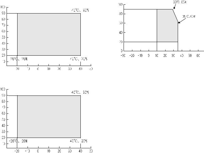
2. Environmental conditions
A. Transport conditions
(1) Transport conditions
Humidity (%) |
B. Use conditions
(%) |
Use envi- |
Humidity |
ronment |
conditions |
|
|
Temperature 

Temperature 

(2) Storage conditions
Humidity (%) |
Temperature 

C. Life(packed conditions)
Photoconductor drum (36 months from the production month) Developer, toner (24 months from the production month)
MX-M182 CONSUMABLE PARTS 4-2
3. Production number identification
<Toner cartridge>
The label on the toner cartridge shows the date of production.
Production |
Serial |
Year/ |
Ver.No. |
place |
number |
Month/ |
|
|
|
Day |
|
<Drum cartridge>
The lot number, printed on the front side flange, is composed of 10 digits, each digit showing the following content:
1 |
2 |
3 |
4 |
5 |
6 |
7 |
8 |
9 |
10 |
The lot number is of 10 digits. Each digit indicates the content as follows. The number is printed on the flange on the front side.
1:Number
For this model, this digit is 2.
2:Alphabet
Indicates the model conformity code. G for this model.
3:Number
Indicates the end digit of the production year.
4:Number or X, Y, Z
Indicates the production month.
X stands for October, Y November, and Z December.
5/6: Number
Indicates the day of the production date.
7:Number
Indicates the day of the month of packing.
X stands for October, Y November, and Z December.
8/9: Number
Indicates the day of the packing date.
10:Alphabet
Indicates the production factory.
MX-M182 CONSUMABLE PARTS 4-3
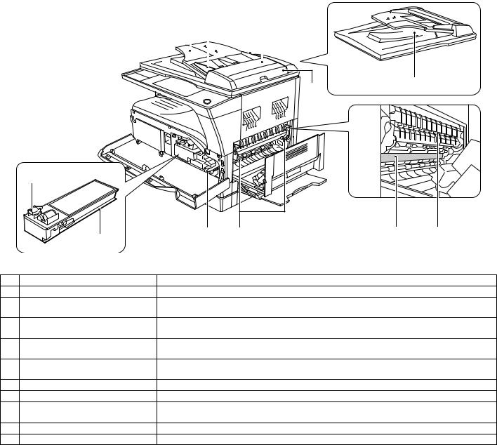
[5] EXTERNAL VIEWS AND INTERNAL STRUCTURES
1. Appearance
1
2 |
3 |
|
8 |
13 |
9 |
|
7 |
|
4 |
|
|
5 |
5 |
|
|
14 |
6 |
10 |
|
15 |
12 |
|
|
11 |
|
|
|
|
16 |
17 |
18 |
|
|
|
||
1 |
USB 2.0 port |
Connect to your computer to this port to use the printer and scanner functions. |
||
|
|
|
|
|
2 |
Charger cleaner |
Use to clean the transfer charger. |
|
|
|
|
|
|
|
3 |
Glass cleaner |
Use to clean the original scanning glass. |
|
|
|
|
|
|
|
4 |
Document glass |
Place an original that you wish to scan face down here. |
|
|
|
|
|
|
|
5 |
Handles |
Use to move the machine. |
|
|
|
|
|
|
|
6 |
Power switch |
Press to turn the machine power on and off. |
|
|
|
|
|
|
|
7 |
Centre tray |
Copies and printed pages are output to this tray. |
|
|
|
|
|
||
8 |
Top tray (when the job separator tray kit is installed) |
Received faxes (when the fax option is installed) and print jobs are delivered to this tray. |
||
|
|
|
|
|
9 |
Operation panel |
Contains operation keys and indicator lights. |
|
|
|
|
|
|
|
10 |
Front cover |
Open to remove paper misfeeds or replace the toner cartridge. |
|
|
|
|
|
||
11 |
Tray 1 |
Tray 1 can hold approximately 250 sheets of copy paper (80 g/m2 (20 lbs.)). |
||
|
|
|
||
12 |
Tray 2 |
Tray 2 can hold approximately 250 sheets of copy paper (80 g/m2 (20 lbs.)). |
||
|
|
|
|
|
13 |
Document cover (when installed) |
Open to make a copy from the document glass. |
|
|
|
|
|
|
|
14 |
Side cover |
Open to remove misfeed paper. |
|
|
|
|
|
|
|
15 |
Side cover handle |
Pull to open the side cover. |
|
|
|
|
|
|
|
16 |
Bypass tray guides |
Adjust to the width of the paper when using the bypass tray. |
|
|
|
|
|
||
17 |
Bypass tray |
Special paper (heavy paper or transparency film) can be fed from the bypass tray. |
||
|
|
|
||
18 |
Bypass tray extension |
Pull out when feeding large paper such as A3 and B4 (11" x 17" and 8-1/2" x 14"). |
||
|
|
|
|
|
MX-M182 EXTERNAL VIEWS AND INTERNAL STRUCTURES 5-1
2. Internal
21 |
22 |
23 |
|||
|
|
|
|
|
|
|
|
|
|
|
|
|
|
|
|
|
|
|
|
|
|
|
|
27
24
|
19 |
|
|
|
|
|
20 |
26 |
25 |
28 |
29 |
|
|
|
|
|
|
19 |
Toner cartridge lock release lever |
To replace the toner cartridge, pull out the toner cartridge while pushing on this lever. |
|||
20 |
Toner cartridge |
Contains toner. |
|
|
|
21 |
Document feeder tray (when the SPF/ |
Place the original(s) that you wish to scan face up here. Up to 40 sheets can be placed. |
|||
|
RSPF is installed) |
|
|
|
|
22 |
Original guides (when the SPF/RSPF is |
Adjust to the size of the originals. |
|
|
|
|
installed) |
|
|
|
|
23 |
Feeding roller cover (when the SPF/ |
Open to remove misfeed originals. |
|
|
|
|
RSPF is installed) |
|
|
|
|
24 |
Right side cover (when the SPF/RSPF is |
Open to remove misfeed originals. |
|
|
|
|
installed) |
|
|
|
|
25 |
Fusing unit release levers |
To remove the paper misfeed in the fusing unit, push down on these levers and remove the paper. |
|||
26 |
Roller rotating knob |
Rotate to remove misfeed paper. |
|
|
|
27 |
Exit area (when the SPF/RSPF is |
Originals exit the machine here after copying/scanning when the SPF/RSPF is used. |
|||
|
installed) |
|
|
|
|
28 |
Photoconductive drum |
Images are formed on the photoconductive drum. |
|
|
|
29 |
Fusing unit paper guide |
Open to remove misfeed paper. |
|
|
|
Warning: The fusing unit is hot. Do not touch the fusing unit when removing misfeed paper. Doing so may cause a burn or injury.
Do not touch the photoconductive drum (green portion) when removing the misfeed paper. Doing so may damage the drum and cause smudges on copies.
Note: The model name is on the front cover of the machine.
MX-M182 EXTERNAL VIEWS AND INTERNAL STRUCTURES 5-2

3. Operation Section
|
1 |
|
|
|
|
|
|
2 |
3 |
4 |
|
5 |
|
|
6 |
|
|
|
|
|
|
7 |
|
|
8 |
|
9 |
|
|
|
10 |
11 |
12 |
||||||||||||||||||||||
|
|
|
|
|
|
|
|
|
|
|
|
|
|
|
|
|
|
|
|
|
|
|
|
|
|
|
|
|
|
|
|
|
|
|
|
|
|
|
|
|
|
|
|
|
|
|
|
|
|
INTERRUPT |
|
||||
|
|
|
|
|
|
|
|
|
|
|
|
|
|
|
|
|
|
|
|
|
|
|
|
|
|
|
|
|
|
|
|
|
|
|
|
|
|
|
|
|
|
|
|
|
|
|
|
|
|
|
|||||
|
|
01 |
02 |
03 |
04 |
05 |
SPEAKER |
|
|
|
|
|
|
|
|
|
|
|
|
|
|
|
|
|
|
|
|
|
|
|
|
|
|
|
|
|
|
|
|
|
|
|
|
|
ABC |
DEF |
|
|
|||||||
|
|
|
|
COPY |
|
|
|
|
FAX STATUS |
|
|
|
|
|
|
|
|
|
|
|
|
|
|
|
|
|
|
|
|
|
|
|
|
|
|
|
|
|
|
|
|
|
|
||||||||||||
|
|
|
|
|
|
|
|
SHIFT |
|
|
|
|
|
|
|
|
|
|
|
|
|
|
|
|
|
|
|
|
|
|
|
|
|
|
|
|
GHI |
|
JKL |
MNO |
|
|
|
|
|
|
|
||||||||
|
|
|
|
|
|
|
|
|
|
|
|
|
|
|
|
|
|
|
|
|
|
|
|
|
|
|
|
|
|
|
|
|
|
|
|
|
|
|
|
|
|
|
|
|
|
|
|
|
|
|
|||||
|
|
06 |
07 |
08 |
09 |
10 |
REDIAL/PAUSE |
|
|
ON LINE |
|
|
|
|
|
|
|
|
|
|
|
|
|
|
|
|
|
|
BACK |
|
OK |
|
|
|
|
|
|
|
|
|
|
|
|
|
|
|
|||||||||
|
|
|
|
|
|
|
|
|
|
DATA |
|
|
SPECIAL |
|
|
|
|
|
|
|
|
|
|
|
|
|
|
|
|
|
|
|
|
|
|
|
|
|
|
|
|
|
|
|
|
|
|||||||||
|
|
|
|
|
|
|
|
|
|
|
|
|
|
|
|
|
|
|
|
|
|
|
|
|
|
|
|
|
|
|
|
|
|
|
|
|
|
|
|
|
|
|
|
|
|
|
|
|
|||||||
|
|
11 |
12 |
13 |
14 |
15 |
|
|
|
|
|
|
|
|
|
FUNCTION |
|
|
|
|
|
|
|
|
|
|
|
|
|
|
|
|
|
|
|
|
PQRS |
|
TUV |
WXYZ |
|
|
|
|
|
|
|
||||||||
|
|
16 |
17 |
18 |
19 |
20 |
SPEED |
|
|
SCAN |
|
|
|
|
|
|
|
|
|
|
|
|
|
|
|
|
|
|
|
|
|
|
|
|
|
|
|
|
|
|
|
|
|
@.-_ |
|
|
|
|
|
|
|
|
|||
|
|
|
|
|
|
|
|
|
|
|
|
|
|
|
|
|
|
|
|
|
|
|
|
|
|
|
|
|
|
|
|
|
|
|
|
|
|
|
|
|
|
|
|
|
|
|
|
||||||||
|
|
|
|
|
|
|
|
|
|
|
|
|
|
|
|
|
|
|
|
|
|
|
|
|
|
|
|
|
|
|
|
|
|
|
|
|
|
|
|
|
|
|
|
|
|
|
|
|
|||||||
|
|
SYMBOL |
|
|
FAX |
LINE |
|
|
COPY EXPOSURE |
PAPER SELECT COPY RATIO AUTO IMAGE |
OUTPUT |
2-SIDED COPY |
|
|
|
|
|
|
|
|
|
|
|
|
|
|
|
|
|
|
|
||||||||||||||||||||||||
|
|
|
|
|
|
|
|
|
|
DATA |
|
|
|
|
|
|
|
|
|
|
|
|
|
|
|
|
|
|
|
|
|
|
|||||||||||||||||||||||
|
|
|
|
|
|
|
|
|
|
|
|
|
|
|
|
SCAN COLOUR MODE |
RESOLUTION ADDRESS |
FORMAT |
ORIGINAL SIZE |
DUPLEX SCAN |
|
|
|
|
|
|
|
|
|
|
|
|
|
|
|
|
|
|
|
|
|||||||||||||||
|
|
21 |
22 |
23 |
24 |
25 |
COMM. SETTING |
|
|
|
|
|
|
|
|
FAX |
PROGRAM |
RESOLUTION ADDRESS |
BROADCAST ORIGINAL SIZE |
DUPLEX SCAN |
|
|
|
|
|
|
|
ACC. #-C |
|
READ-END |
|
|
|
|
|
|
|
||||||||||||||||||
|
|
|
|
|
|
|
|
|
|
|
|
|
|
|
|
|
|
|
|
|
|
|
|
|
|
|
|
|
|
|
|
|
|
|
|
|
|
|
|
|
|
|
|
|
|
|
|
|
|
|
|||||
|
|
|
|
|
|
|
|
SPACE/– |
|
|
|
|
|
|
|
|
|
|
|
|
|
|
|
|
|
|
|
|
|
|
|
|
|
|
|
|
|
|
|
|
|
|
|
|
|
|
|
|
|
|
|
|
|
|
|
|
|
|
|
|
|
|
|
|
|
|
|
|
|
|
|
|
|
|
|
|
|
|
|
|
|
|
|
|
|
|
|
|
|
|
|
|
|
|
|
|
|
|
|
|
|
|
|
|
|
|
|
||||
|
|
|
|
|
|
|
|
|
|
13 |
|
|
14 |
|
15 |
16 |
17 |
18 |
19 |
|
20 |
|
21 |
|
22 |
|
23 |
24 |
25 |
26 |
|
||||||||||||||||||||||||
|
|
|
|
|
|
|
|
|
|
|
|
|
|
|
|
|
|
|
|
|
|
|
|
|
|
|
|
|
|
|
|
|
|
|
|
||||||||||||||||||||
1 |
Keys for fax function (when the fax |
These are used in fax mode. |
|
|
|
|
|
|
|
|
|
|
|
|
|
|
|
|
|
|
|
|
|
|
|
|
|
|
|
|
|
|
|
|
|
||||||||||||||||||||
|
option is installed) |
|
|
|
|
|
|
|
|
|
|
|
|
|
|
|
|
|
|
|
|
|
|
|
|
|
|
|
|
|
|
|
|
|
|
|
|
|
|
|
|
|
|
|
|
|
|
|
|
|
|||||
|
|
|
|
|
|||||||||||||||||||||||||||||||||||||||||||||||||||
2 |
[COPY] key / indicator |
|
|
Press to select copy mode. If pressed when "Ready to copy." appears or during warm-up, the total |
|||||||||||||||||||||||||||||||||||||||||||||||||||
|
|
|
|
|
|
|
|
|
|
number of sheets used appears while the key is pressed. |
|
|
|
|
|
|
|
|
|
|
|
|
|
|
|
|
|
|
|||||||||||||||||||||||||||
|
|
|
|
|
|
|
|
|
|
|
|
|
|
|
|
|
|
|
|
|
|
|
|
|
|
|
|
|
|
|
|
|
|
|
|
|
|
||||||||||||||||||
3 |
[PRINT] key / indicator |
|
|
Press to select print mode. |
|
|
|
|
|
|
|
|
|
|
|
|
|
|
|
|
|
|
|
|
|
|
|
|
|
|
|
|
|
|
|
|
|
||||||||||||||||||
|
• ONLINE indicator |
|
|
|
Print jobs can be received when this indicator is lit. |
|
|
|
|
|
|
|
|
|
|
|
|
|
|
|
|
|
|
|
|
||||||||||||||||||||||||||||||
|
• DATA indicator |
|
|
|
|
This lights steadily when there is a print job in memory that has not been printed, and blinks |
|||||||||||||||||||||||||||||||||||||||||||||||||
|
|
|
|
|
|
|
|
|
|
during printing. |
|
|
|
|
|
|
|
|
|
|
|
|
|
|
|
|
|
|
|
|
|
|
|
|
|
|
|
|
|
|
|
|
|
|
|
|
|
|
|
|
|
||||
|
|
|
|
|
|||||||||||||||||||||||||||||||||||||||||||||||||||
4 |
[SCAN] key / indicator |
|
|
Press to select scan mode. To use the machine as a network scanner, see the "Operation Guide |
|||||||||||||||||||||||||||||||||||||||||||||||||||
|
|
|
|
|
|
|
|
|
|
(NETWORK EXPANSION KIT)" that accompanies the machine. |
|
|
|
|
|
|
|
|
|
|
|
||||||||||||||||||||||||||||||||||
|
|
|
|
|
|
|
|
|
|
|
|
|
|
|
|
|
|
|
|
|
|
|
|
|
|
|
|
|
|
|
|
|
|
|
|
||||||||||||||||||||
5 |
[FAX STATUS] key (when the fax option |
This key is used in fax mode. |
|
|
|
|
|
|
|
|
|
|
|
|
|
|
|
|
|
|
|
|
|
|
|
|
|
|
|
|
|
|
|
|
|
||||||||||||||||||||
|
is installed) |
|
|
|
|
|
|
|
|
|
|
|
|
|
|
|
|
|
|
|
|
|
|
|
|
|
|
|
|
|
|
|
|
|
|
|
|
|
|
|
|
|
|
|
|
|
|
|
|
|
|
|
|||
|
|
|
|
|
|
|
|
|
|
|
|
|
|
|
|
|
|
|
|
|
|
|
|
|
|
|
|
|
|
|
|
|
|
|
|
|
|
|
|
|
|
||||||||||||||
6 |
Display |
|
|
|
|
|
|
Shows various messages. |
|
|
|
|
|
|
|
|
|
|
|
|
|
|
|
|
|
|
|
|
|
|
|
|
|
|
|
|
|
|
|
|
|
||||||||||||||
|
|
|
|
|
|
|
|
|
|
|
|
|
|
|
|
|
|
|
|
|
|
|
|
|
|
|
|
||||||||||||||||||||||||||||
7 |
[BACK] key |
|
|
|
|
|
Press to return the display to the previous screen. |
|
|
|
|
|
|
|
|
|
|
|
|
|
|
|
|
|
|
|
|
||||||||||||||||||||||||||||
|
|
|
|
|
|
||||||||||||||||||||||||||||||||||||||||||||||||||
8 |
Copy number display |
|
|
|
The selected number of copies appears. During copying, this shows the remaining number of |
||||||||||||||||||||||||||||||||||||||||||||||||||
|
|
|
|
|
|
|
|
|
|
copies. |
|
|
|
|
|
|
|
|
|
|
|
|
|
|
|
|
|
|
|
|
|
|
|
|
|
|
|
|
|
|
|
|
|
|
|
|
|
|
|
|
|
|
|||
|
|
|
|
|
|
|
|
|
|
|
|
|
|
|
|
|
|
|
|
|
|
|
|
|
|
|
|
|
|
|
|
|
|
|
|
|
|||||||||||||||||||
9 |
[OK] key |
|
|
|
|
|
|
Press to enter the selected setting. |
|
|
|
|
|
|
|
|
|
|
|
|
|
|
|
|
|
|
|
|
|
|
|
|
|
|
|
|
|||||||||||||||||||
|
|
|
|
|
|
|
|
|
|
|
|
|
|
|
|
|
|
|
|
|
|
|
|
|
|
|
|
|
|
|
|
|
|
|
|
||||||||||||||||||||
10 |
Numeric keys |
|
|
|
|
|
Use to select the number of copies. |
|
|
|
|
|
|
|
|
|
|
|
|
|
|
|
|
|
|
|
|
|
|
|
|
|
|
|
|
||||||||||||||||||||
|
|
|
|
|
|
|
|
|
|
|
|
|
|
|
|
|
|
|
|
|
|
|
|
|
|
|
|||||||||||||||||||||||||||||
11 |
[C] key |
|
|
|
|
|
|
Press to clear the set number of copies or stop a copy run. |
|
|
|
|
|
|
|
|
|
|
|
|
|
|
|
|
|
|
|||||||||||||||||||||||||||||
|
|
|
|
|
|
|
|
|
|
|
|
|
|
|
|||||||||||||||||||||||||||||||||||||||||
12 |
[INTERRUPT] key ( |
) / INTERRUPT |
Interrupts a copy run to allow an interrupt copy job to be performed. |
|
|
|
|
|
|
|
|
|
|
|
|||||||||||||||||||||||||||||||||||||||||
|
indicator |
|
|
|
|
|
|
|
|
|
|
|
|
|
|
|
|
|
|
|
|
|
|
|
|
|
|
|
|
|
|
|
|
|
|
|
|
|
|
|
|
|
|
|
|
|
|
|
|
|
|
|
|
||
|
|
|
|
|
|
|
|
|
|
|
|
|
|
|
|
|
|
|
|
|
|
|
|
|
|
|
|
|
|
|
|
|
|
|
|
||||||||||||||||||||
13 |
[FAX] key / indicator (when the fax option |
This key is used in fax mode. |
|
|
|
|
|
|
|
|
|
|
|
|
|
|
|
|
|
|
|
|
|
|
|
|
|
|
|
|
|
|
|
|
|
||||||||||||||||||||
|
is installed) |
|
|
|
|
|
|
|
|
|
|
|
|
|
|
|
|
|
|
|
|
|
|
|
|
|
|
|
|
|
|
|
|
|
|
|
|
|
|
|
|
|
|
|
|
|
|
|
|
|
|
|
|||
|
LINE indicator, DATA indicator |
|
|
|
|
|
|
|
|
|
|
|
|
|
|
|
|
|
|
|
|
|
|
|
|
|
|
|
|
|
|
|
|
|
|
|
|
|
|
|
|
|
|
|
|
|
|
|
|
||||||
|
|
|
|
|
|
|
|
|
|
|
|
|
|
|
|
|
|
|
|
|
|
|
|
|
|
|
|
|
|
|
|
|
|
|
|
||||||||||||||||||||
14 |
[SPECIAL FUNCTION] key |
|
|
Press to select special functions. |
|
|
|
|
|
|
|
|
|
|
|
|
|
|
|
|
|
|
|
|
|
|
|
|
|
|
|
|
|
|
|
||||||||||||||||||||
|
|
|
|
|
|
|
|
|
|
|
|
|
|||||||||||||||||||||||||||||||||||||||||||
15 |
[EXPOSURE] key |
|
|
|
Use to select the exposure mode. "AUTO", "TEXT", or "PHOTO" can be selected. |
|
|
|
|
|
|
|
|||||||||||||||||||||||||||||||||||||||||||
|
|
|
|
|
|
|
|
|
|
|
|
|
|
|
|
|
|
|
|
|
|
|
|
|
|
|
|
|
|
|
|
|
|||||||||||||||||||||||
16 |
[PAPER SELECT] key |
|
|
Use to manually select a paper tray. |
|
|
|
|
|
|
|
|
|
|
|
|
|
|
|
|
|
|
|
|
|
|
|
|
|
|
|
|
|||||||||||||||||||||||
|
|
|
|
|
|
|
|
|
|
|
|
|
|
|
|
|
|
|
|
|
|
|
|
|
|
||||||||||||||||||||||||||||||
17 |
[COPY RATIO] key |
|
|
|
Press to select a reduction or enlargement copy ratio. |
|
|
|
|
|
|
|
|
|
|
|
|
|
|
|
|
|
|
|
|
||||||||||||||||||||||||||||||
|
|
|
|
|
|
|
|
|
|
|
|
|
|
|
|
|
|
|
|
|
|
|
|
|
|
||||||||||||||||||||||||||||||
18 |
[AUTO IMAGE] key |
|
|
|
Press to have the copy ratio selected automatically. |
|
|
|
|
|
|
|
|
|
|
|
|
|
|
|
|
|
|
|
|
||||||||||||||||||||||||||||||
|
|
|
|
|
|
|
|
|
|
|
|
|
|
|
|
|
|
|
|
|
|
|
|
|
|
|
|
|
|
|
|
|
|
|
|
|
|
||||||||||||||||||
19 |
[OUTPUT] key |
|
|
|
|
Use to select the sort function. |
|
|
|
|
|
|
|
|
|
|
|
|
|
|
|
|
|
|
|
|
|
|
|
|
|
|
|
|
|
|
|
||||||||||||||||||
|
|
|
|
|
|
|
|
|
|
|
|
|
|
|
|
|
|
|
|
|
|
|
|
|
|
|
|
|
|
|
|
|
|||||||||||||||||||||||
20 |
[2-SIDED COPY] key |
|
|
Select the two-sided copying mode. |
|
|
|
|
|
|
|
|
|
|
|
|
|
|
|
|
|
|
|
|
|
|
|
|
|
|
|
|
|||||||||||||||||||||||
|
(MX-M182D/MX-M202D/MX-M232D) |
|
|
|
|
|
|
|
|
|
|
|
|
|
|
|
|
|
|
|
|
|
|
|
|
|
|
|
|
|
|
|
|
|
|
|
|
|
|
|
|
|
|
|
|
|
|
||||||||
|
|
|
|
|
|
|
|
|
|
|
|
|
|
||||||||||||||||||||||||||||||||||||||||||
21 |
Arrow keys |
|
|
|
|
|
Press to move the highlighting (which indicates that an item is selected) in the display. |
|
|
|
|
|
|
||||||||||||||||||||||||||||||||||||||||||
|
|
|
|
|
|
|
|||||||||||||||||||||||||||||||||||||||||||||||||
22 |
[ACC.#-C] key ( |
) |
|
|
|
Press the end the use of an account and return the display to the account number entry screen. |
|||||||||||||||||||||||||||||||||||||||||||||||||
|
|
|
|
|
|
|
|
|
|
|
|
|
|
|
|
||||||||||||||||||||||||||||||||||||||||
23 |
[0] key |
|
|
|
|
|
|
Press during a continuous copy run to display the number of copies completed. |
|
|
|
|
|
|
|
||||||||||||||||||||||||||||||||||||||||
|
|
|
|
|
|
||||||||||||||||||||||||||||||||||||||||||||||||||
24 |
[READ-END] key ( |
) |
|
|
When copying in sort mode from the document glass, press this key when you have finished scanning |
||||||||||||||||||||||||||||||||||||||||||||||||||
|
|
|
|
|
|
|
|
|
|
the original pages and are ready to start copying. |
|
|
|
|
|
|
|
|
|
|
|
|
|
|
|
|
|
|
|
|
|
|
|
||||||||||||||||||||||
|
|
|
|
|
|
|
|
|
|
|
|
|
|
|
|
|
|
||||||||||||||||||||||||||||||||||||||
25 |
[CA] key |
|
|
|
|
|
|
Clears all selected settings and returns the machine to the default settings. |
|
|
|
|
|
|
|
|
|
||||||||||||||||||||||||||||||||||||||
|
|
|
|
|
|
|
|||||||||||||||||||||||||||||||||||||||||||||||||
26 |
[START] key ( |
|
) / indicator |
|
|
Copying is possible when this indicator is on. Press the key to start copying. This indicator blinks when |
|||||||||||||||||||||||||||||||||||||||||||||||||
|
|
|
|
|
|
|
|
|
|
auto power shut-off mode has activated. Press the key to return to normal operation. |
|
|
|
|
|
|
|||||||||||||||||||||||||||||||||||||||
|
|
|
|
|
|
|
|
|
|
|
|
|
|
|
|
|
|
|
|
|
|
|
|
|
|
|
|
|
|
|
|
|
|
|
|
|
|
|
|
|
|
|
|
|
|
|
|
|
|
|
|
|
|
|
|
MX-M182 EXTERNAL VIEWS AND INTERNAL STRUCTURES 5-3
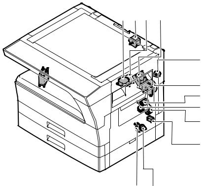
4. Motor, solenoid, clutch
11 


13 1 2 12
3
4 |
6 |
5 |
7 |
8
|
|
|
10 |
9 |
|
|
|
|
|
No. |
Name |
Code |
|
Function operation |
|
|
|
|
|
1 |
Mirror motor |
MRM |
Drives the optical mirror base (scanner unit). |
|
|
|
|
|
|
2 |
Toner motor |
TM |
Toner supply |
|
|
|
|
|
|
3 |
Duplex motor |
DPX |
Switchback operation and paper exit motor in duplex. (MX-M182D/M202D/M232D) |
|
|
|
|
|
|
4 |
Main motor |
MM |
Drives the machine. |
|
|
|
|
|
|
5 |
1st tray paper feed clutch |
CPSCL1 |
Drives the pick up roller |
|
|
|
|
|
|
6 |
PS clutch |
RRC |
Drives the resist roller |
|
|
|
|
|
|
7 |
Bypass tray paper transport clutch |
MPTC |
Drives the bypass tray paper transport roller. |
|
|
|
|
|
|
8 |
Bypass tray paper feed solenoid |
MPFS |
Bypass tray paper feed solenoid |
|
|
|
|
|
|
9 |
2nd tray transport clutch |
FSCL1 |
Drives the 2nd tray transport roller. (MX-M202D/M232D) |
|
|
|
|
|
|
10 |
2nd tray paper feed clutch |
PSCL2 |
Drives the 2nd tray paper feed roller. (MX-M202D/M232D) |
|
|
|
|
|
|
11 |
Exhaust fan motor |
PSFM |
Cools the inside of the machine. |
|
|
|
|
|
|
12 |
Cooling fan motor |
VFM |
Cools the inside of the machine. |
|
|
|
|
|
|
13 |
Shifter motor |
SFTM |
Drives the shifter motor. |
|
|
|
|
|
|
MX-M182 EXTERNAL VIEWS AND INTERNAL STRUCTURES 5-4
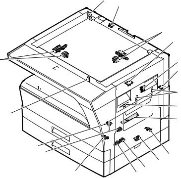
5. Sensor, switch
1
17
20
3
|
(AB) |
|
|
(INCH) |
(AB) |
19 |
|
|
|
(INCH) |
16

15

18
4
5 |
|
|
6 |
2 |
|
7 |
|
|
|
14 |
|
|
13 |
|
8 |
|
|
|
|
|
9 |
|
12 |
10 |
|
11 |
|
|
|
No. |
Name |
Code |
Function operation |
|
|
|
|
1 |
Mirror home position sensor |
MHPS |
Detects the mirror (scanner unit) home position. |
|
|
|
|
2 |
Side door switch |
DSWR |
Side door open detection |
|
|
|
|
3 |
Paper exit sensor (paper exit side) |
POD1 |
Detects paper exit. |
|
|
|
|
4 |
Paper exit sensor (DUP side) |
PDPX |
Paper transport detection |
|
|
|
|
5 |
Thermistor |
RTH |
Fusing section temperature detection |
|
|
|
|
6 |
Thermostat |
RDTCT |
Fusing section abnormally high temperature detection |
|
|
|
|
7 |
Toner density sensor |
TCS |
Detects the toner density in the developing unit. |
|
|
|
|
8 |
2nd tray detection switch |
CSD2 |
2nd tray detection |
|
|
|
|
9 |
Bypass tray sensor |
MPED |
Bypass tray transport detection |
|
|
|
|
10 |
2nd tray door open/close sensor |
DRS2 |
2nd tray door open/close detection (MX-M202D/M232D) |
|
|
|
|
11 |
2nd tray door paper pass sensor |
PPD2 |
2nd tray paper entry detection (MX-M202D/M232D) |
|
|
|
|
12 |
2nd tray paper empty sensor |
CSS2 |
2nd tray paper empty detection (MX-M202D/M232D) |
|
|
|
|
13 |
Paper in sensor |
PIN |
Paper transport detection |
|
|
|
|
14 |
Tray empty |
CSS1 |
Tray paper entry detection |
|
|
|
|
15 |
Front cover SW |
DSWF |
Front cover open detection |
|
|
|
|
16 |
Power switch |
MAIN SW |
Turns ON/OFF the main power source. |
|
|
|
|
17 |
OC sensor |
OCSW |
Original cover and SPF open/close detection |
|
|
|
|
18 |
Shifter home position sensor |
SFTHP |
Shifter home position detection |
|
|
|
|
19 |
Original size sensor(Main Scaning) |
DSIN0 |
Original size detection |
|
|
|
|
20 |
Original size sensor(Sub Scaning) |
DSIN1 |
Original size detection |
|
|
|
|
MX-M182 EXTERNAL VIEWS AND INTERNAL STRUCTURES 5-5
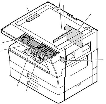
6. PWB unit
|
2 |
1 |
8 |
|
3
7
9
4 |
6
5
No. |
Name |
Function operation |
|
|
|
1 |
Copy lamp Inverter PWB |
Copy lamp control |
|
|
|
2 |
CCD sensor PWB |
Image scanning |
|
|
|
3 |
Main control PWB |
Main control PWB |
|
|
|
4 |
2nd tray PWB |
2nd tray control |
|
|
|
5 |
High voltage PWB |
High voltage control |
|
|
|
6 |
Power PWB |
AC power input/DC power control |
|
|
|
7 |
Operation main PWB |
Operation panel input/Display, operation panel section control |
|
|
|
8 |
USB I/F PWB |
Connect a USB device |
|
|
|
9 |
LCD OPE PWB |
Display and operation panel control |
|
|
|
MX-M182 EXTERNAL VIEWS AND INTERNAL STRUCTURES 5-6
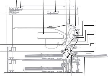
7. Cross sectional view
1 |
2 |
3 |
4 |
5 6 |
7 |
|
18 |
|
|
|
|
|
|
|
|
|
|
|
|
8 |
|
|
|
|
|
|
9 |
|
|
|
|
|
|
10 |
|
|
|
|
|
|
11 |
|
|
|
|
|
|
12 |
23 |
|
|
|
|
|
13 |
|
|
|
|
|
14 |
|
|
|
|
|
|
|
|
22 |
|
|
|
|
|
15 |
|
|
|
|
212019 17 |
16 |
|
No. |
Name |
Function/Operation |
|
|
|
1 |
Copy lamp |
Image radiation lamp |
|
|
|
2 |
Copy lamp unit |
Operates in synchronization with No. 2/3 mirror unit to radiate documents |
|
|
sequentially. |
|
|
|
3 |
LSU unit |
Converts image signals into laser beams to write on the drum. |
|
|
|
4 |
Lens unit |
Reads images with the lens and the CCD. |
|
|
|
5 |
MC holder unit |
Supplies negative charges evenly on the drum. |
|
|
|
6 |
Paper exit roller |
Used to discharge paper. |
|
|
|
7 |
Transport roller |
Used to transport paper. |
|
|
|
8 |
Upper heat roller |
Fuses toner on paper (with the teflon roller). |
|
|
|
9 |
Lower heat roller |
Fuses toner on paper (with the silicon rubber roller). |
|
|
|
10 |
Waste toner transport roller |
Transports waste toner to the waste toner box. |
|
|
|
11 |
Drum unit |
Forms images. |
|
|
|
12 |
Transfer charger unit |
Transfer images (on the drum) onto paper. |
|
|
|
13 |
DUP follower roller |
Transports paper for duplex. |
|
|
|
14 |
Duplex transport roller |
Transports paper for duplex . |
|
|
|
15 |
Resist roller |
Takes synchronization between the paper lead edge and the image lead edge. |
|
|
|
16 |
Bypass tray |
Bypass tray |
|
|
|
17 |
Bypass tray paper pick up roller |
Picks up paper in bypass tray. |
|
|
|
18 |
No. 2/3 mirror unit |
Reflects the images from the copy lamp unit to the lens unit. |
|
|
|
19 |
Bypass tray transport roller |
Transports paper from the bypass tray. |
|
|
|
20 |
2nd tray paper transport roller |
Transports paper from the 2nd tray. (MX-M202D/M232D) |
|
|
|
21 |
2nd tray paper pick up roller |
Picks up paper from the 2nd tray. (MX-M202D/M232D) |
|
|
|
22 |
1st tray paper feed roller |
Picks up paper from the 1st tray. |
|
|
|
23 |
MG roller |
Puts toner on the OPC drum. |
|
|
|
MX-M182 EXTERNAL VIEWS AND INTERNAL STRUCTURES 5-7
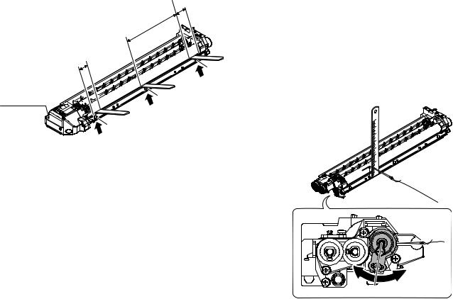
[6] ADJUSTMENTS
1. Adjustment item list
|
Section |
|
Adjustment item |
Adjustment procedure/SIM No. |
|
|
|
|
|
A |
Process |
(1) |
Developing doctor gap adjustment |
Developing doctor gap adjustment |
|
section |
|
|
|
|
(2) |
MG roller main pole position adjustment |
MG roller main pole position adjustment |
|
|
|
|
|
|
|
|
(3) |
Developing bias voltage check |
|
|
|
|
|
|
|
|
(4) |
Main charger voltage check |
|
|
|
|
|
|
B |
Mechanism |
(1) |
Image position adjustment |
SIM-50 |
|
section |
|
|
|
|
(2) |
Main scanning direction (FR direction) distortion balance |
No. 2/3 mirror base unit installing position adjustment |
|
|
|
|
adjustment |
|
|
|
|
Copy lamp unit installing position adjustment |
|
|
|
|
|
|
|
|
(3) |
Main scanning direction (FR direction) distortion adjustment |
Rail height adjustment |
|
|
|
|
|
|
|
(4) |
Sub scanning direction (scanning direction) distortion |
Winding pulley position adjustment |
|
|
|
adjustment |
|
|
|
|
|
|
|
|
(5) |
Main scanning direction (FR direction) magnification ratio |
SIM 48-1 |
|
|
|
adjustment |
|
|
|
|
|
|
|
|
(6) |
Sub scanning direction (scanning direction) magnification ratio |
OC mode in copying (SIM 48-1) |
|
|
|
adjustment |
|
|
|
|
SPF mode in copying (SIM 48-5) |
|
|
|
|
|
|
|
|
(7) |
Off center adjustment |
OC mode (SIM 50-12) |
|
|
|
|
|
|
|
|
|
SPF mode (SIM 50-12) |
|
|
|
|
|
C |
Image density |
(1) |
Copy mode |
SIM 46-2 |
|
adjustment |
|
|
|
|
|
|
|
|
2. Copier adjustment
A. Process section
(1) Developing doctor gap adjustment
1)Loosen the developing doctor fixing screw A.
2)Insert a thickness gauge of 1.5mm to the three positions at 20mm and 150mm from the both ends of the developing doctor as shown.
20mm
150mm
20mm
A
1


 A DV front cover


3
A
2
3)Push the developing doctor in the arrow direction, and tighten the fixing screws of the developing doctor in the sequence of 13233.
4)Check the clearance of the developing doctor. If it is within the specified range, then fix the doctor fixing screw with screw lock.
*When inserting a thickness gauge, be careful not to scratch the developing doctor and the MG roller.
<Adjustment specification>
Developing doctor gap
Both ends (20mm from the both ends) : 1.5 0.1mm
0.1mm
C (Center) (150mm from the both ends) :1.5 0.1mm
0.1mm
(2) MG roller main pole position adjustment
1)Remove the DV front cover, and put the developing tank on a flat surface.
2)Tie a string to a needle or a pin.
3)Hold the string and bring the needle close to the MG roller horizontally. (Do not use paper clip, which is too heavy to make a correct adjustment.) (Put the developing unit horizontally for this adjustment.)
4)Do not bring the needle into contact with the MG roller, but bring it to a position 2 or 3mm apart from the MG roller. Mark the point on the MG roller which is on the extension line from the needle tip.
5)Measure the distance from the marking position to the top of the doctor plate of the developing unit to insure that it is 18mm.
If the distance is not within the specified range, loosen the fixing screw A of the main pole adjustment plate, and move the adjustment plate in the arrow direction to adjust.
MX-M182 ADJUSTMENT 6-1
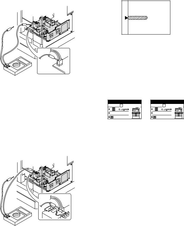
(3) Developing bias voltage check
Note:Use a digital multi-meter with an internal resistance of 10M or more.
1)Set the digital multi-meter range above 500 Vdc.
2)Put the test rod of the digital multi-meter on the developing bias voltage output check pin.
3)Turn on the power, execute SIM25-1.
<Specification>
Mode |
Specification |
|
|
Developing bias voltage |
DC - 400±10V |
|
|
(4) Grid bias voltage check
Note:Use a digital multi-meter with an internal resistance of 10M or more.
1)Set the digital multi-meter range above 600 Vdc.
2)Put the test rod of the digital multi-meter on the grid bias voltage output check pin.
3)Turn on the power.
(The voltage is outputted in the grid bias High output mode during warming up, and in the grid bias Low output mode when warming up is completed.)
<Specification>
Mode |
Specification |
|
|
Grid bias LOW |
DC - 380±8V |
|
|
Grid bias HIGH |
DC - 525±10V |
|
|
B. Mechanism section
(1) Image position adjustment
a. OC image lead edge position adjustment (SIM 50-1)
Note:In advance to this adjustment, the sub scanning magnification ratio adjustment must be performed.
1) Set a scale on the OC table as shown below.
2)Make a copy.
3)Check the copy output. If necessary, perform the following adjustment procedures.
4)Execute SIM 50-01.
Select a desired mode with the arrow keys, enter the adjustment value with 10-key, and press [OK] key.
When [START] key is pressed, a sheet is printed.
(Mode selection window 1) |
|
(Mode selection window 2) |
|||||||
|
|
|
|
|
|
|
|||
Sim50-1 LEAD EDGE |
|
|
Sim50-1 LEAD EDGE |
||||||
|
|
|
|
|
|
|
4:DEN-A |
50 |
|
|
1:TRAY1 |
50 |
|
|
|
|
|
||
|
2:TRAY2 |
50 |
|
|
|
|
5:RRC-A |
1 |
|
|
3:MFT |
50 |
|
|
|
|
6:DEN-B |
50 |
|
1/2 [ 1- 99] |
50 |
|
|
|
2/2 [ 1- 99] |
50 |
|
||
|
|
|
|
|
|
|
|||
|
(Copy start window) |
|
(Copy execution window) |
||||||
Ready to copy. |
Copies in progress. |
S |
S |
100% |
100% |
A4 |
A4 |
<Adjustment specification>
Adjustment |
SIM |
Display |
Set |
Spec |
Set |
mode |
|
text array |
value |
value |
range |
|
|
|
|
|
|
OC image lead |
SIM |
RRC-A |
R/0.1 |
Lead edge |
1 - 99 |
edge position |
50-1 |
|
|
void: |
|
|
|
|
|
1 - 4mm |
|
Main cassette |
|
TRAY1 |
H/0.1 |
|
|
print start |
|
|
|
Image loss: |
|
position |
|
|
|
|
|
|
|
|
|
3mm or |
|
2nd cassette |
|
TRAY2 |
|
|
|
|
|
less |
|
||
print start |
|
|
|
|
|
|
|
|
|
|
|
position |
|
|
|
|
|
|
|
|
|
|
|
Multi bypass |
|
MFT |
|
|
|
tray print start |
|
|
|
|
|
position |
|
|
|
|
|
|
|
|
|
|
|
Lead edge void |
|
DEN-A |
B/0.05 |
|
|
|
|
|
|
|
|
5)Set the OC lead edge position set value (RRC-A) to [1]
The OC image scanning start position is shifted inside the document edge.
6)Set the main cassette lead edge void adjustment value (DEN-A)* to [1] The lead edge void becomes the minimum.
MX-M182 ADJUSTMENT 6-2
7)Set the main cassette print start position value (TRAY1) to [1] and make a copy.
The print start position is shifted inside the document edge.
5mm |
5 |
4mm |
10 |
*The dimension varies depending on the model.
8)Measure the image loss R of the copied image. Enter the set value of the image scanning lead edge position (RRC-A) again.
•1 step of the set value corresponds to about 0.1mm shift.
•Calculate the set value from the formula below. R/0.1(mm) = Image loss set value
<R: Image loss measurement value (mm)>
5mm |
0mm |
5 |
10 |
*The scanning edge is set.
(A line may be printed by scanning the document edge.)
Example: 4/0.1 = 40 = about 40
Note:If the set value is not obtained from the above formula, perform the fine adjustment.
9)Measure the distance H between the paper lead edge and the image print start position. Set the image print start position set value
(TRAY1) again.
•1 step of the set value corresponds to about 0.1mm shift.
•Calculate the set value from the formula below. H/0.1(mm) = Image print start position set value
<H: Print start position measurement value (mm)>
0mm |
0mm |
5 |
10 |
*Fit the print edge with the paper edge, and perform the lead edge adjustment.
Example: 5/0.1 = 50 = about 50
Note:If the set value is not obtained from the above formula, perform the fine adjustment.
10) Set the lead edge void adjustment value (DEN-A)* again.
•1 step of the set value corresponds to about 0.1mm shift.
•Calculate the set value from the formula below.
B/0.05 (mm) = Lead edge void adjustment value <B: Lead edge void (mm)>
2.5mm |
5 |
2.5mm |
10 |
Example: |
When setting the lead edge void to 2.5mm |
|
:2.5 /0.05 = about 50 |
Note:If the set value is not obtained from the above formula, perform the fine adjustment.
b. SPF image lead edge position adjustment (SIM50-6)
1) Set a scale on the OC table as shown below.
Note:Since the printed copy is used as a test chart, put the scale in parallel with the edge lines.
2)Make a copy, Then use the copy output as an original to make an SPF copy again.
3)Check the copy output. If necessary, perform the following adjustment procedures.
4)Execute SIM 50-6.
5)Set the SPF lead edge position set value (SIDE1) so that the same image is obtained as that obtained in the previous OC image lead edge position adjustment.
(Mode selection window)
Sim50-6 SPF EDGE
1:SIDE1 |
50 |
2:SIDE2 |
50 |
3:END EDGE |
50 |
[ 1- 99] |
50 |
(Copy start window) |
(Copy execution window) |
Ready to copy. |
Copies in progress. |
S |
S |
100% |
100% |
A4 |
A4 |
MX-M182 ADJUSTMENT 6-3
Loading...