


 Loading...
 W300 IEM

Instructions for use
.
Thank you for choosing Sennheiser!
We have designed this product to give you reliable operation over many years. Over half a century of accumulated expertise in the design and manufacture of high-quality electro-acoustic equipment have made Sennheiser a world-leading company in this field.
Please take a few moments to read these instructions carefully, as we want you to enjoy your new Sennheiser products quickly and to the fullest.
40
Contents |
|
The ew 300 IEM G2 system .................................................................................. |
42 |
The channel bank system ............................................................................................. |
42 |
Safety instructions ................................................................................................. |
43 |
System components .............................................................................................. |
43 |
Overview of operating controls ........................................................................... |
44 |
SR 300 IEM G2 stereo transmitter ............................................................................... |
44 |
EK 300 IEM G2 stereo receiver ..................................................................................... |
45 |
Indications and displays on the transmitter ............................................................. |
46 |
Indications and displays on the receiver ................................................................... |
46 |
Preparing the components for use ..................................................................... |
48 |
SR 300 IEM G2 stereo transmitter ............................................................................... |
48 |
EK 300 IEM G2 stereo receiver ..................................................................................... |
51 |
Using the components .......................................................................................... |
52 |
Switching the components on/off .............................................................................. |
52 |
Adjusting the volume .................................................................................................... |
52 |
Adjusting the balance .................................................................................................... |
53 |
Activating/deactivating the lock mode ..................................................................... |
53 |
Attaching the receiver to clothing .............................................................................. |
53 |
The operating menu ............................................................................................... |
54 |
The buttons ..................................................................................................................... |
54 |
Overview of menus ......................................................................................................... |
55 |
Working with the operating menu ............................................................................. |
55 |
Operating menu of the stereo transmitter ................................................................ |
57 |
Operating menu of the stereo receiver ...................................................................... |
59 |
Adjustment tips for the operating menu .......................................................... |
62 |
Switching between channel banks ............................................................................. |
62 |
Switching between the channels in a channel bank ............................................... |
62 |
Selecting the frequencies to be stored |
|
in the channel bank “U” ....................................................................................................... |
62 |
Scanning the channel banks for free channels |
|
(receiver only) ........................................................................................................................ |
62 |
Multi-channel operation ................................................................................................ |
63 |
Adjusting the squelch threshold (receiver only) ...................................................... |
63 |
Stereo/FOCUS selection (receiver only) ..................................................................... |
64 |
Limiting the volume at the headphone output (receiver only) ............................ |
64 |
Activating/deactivating the frequency boost (receiver only) .............................. |
64 |
Adjusting the sensitivity (transmitter only) ............................................................ |
64 |
Selecting the standard display .................................................................................... |
65 |
Entering a name .............................................................................................................. |
65 |
Loading the factory-preset default settings ............................................................. |
66 |
Activating/deactivating the pilot tone evaluation (receiver only) ...................... |
66 |
Adjusting the contrast of the graphic display (transmitter only) ....................... |
66 |
Stereo/Mono selection (transmitter only) ................................................................ |
66 |
Activating/deactivating the lock mode ..................................................................... |
67 |
Exiting the operating menu .......................................................................................... |
67 |
Troubleshooting ...................................................................................................... |
68 |
Error checklist .................................................................................................................. |
68 |
Recommendations and tips .......................................................................................... |
69 |
Care and maintenance ........................................................................................... |
69 |
Additional information .......................................................................................... |
70 |
HDX noise reduction ....................................................................................................... |
70 |
Wireless transmission systems ................................................................................... |
70 |
Squelch ............................................................................................................................. |
71 |
Specifications .......................................................................................................... |
72 |
Connector assignment ................................................................................................... |
73 |
Accessories .............................................................................................................. |
73 |
41
The ew 300 IEM G2 system
With the Sennheiser evolution wireless in-ear monitoring system ew 300 IEM G2 (suitable for both stage and broadcast use), musicians, video and sound amateurs, reporters/broadcasters, etc. can directly monitor the received sound signals without troublesome cables or monitor speakers being required. In addition, the system can also be used for any application where talkback signals are to be transmitted.
The evolution wireless in-ear monitoring system ew 300 IEM G2 is a highquality state-of-the-art RF transmission systems with a high level of operational reliability and ease of use. Transmitter and receiver permit wireless transmission with studio-quality sound. The excellent transmission reliability of the ew 300 IEM G2 system is based on the use of
yfurther optimized PLL synthesizer and microprocessor technology,
ythe HDX noise reduction system,
ythe pilot tone squelch control (during stereo operation),
yand the scan function for scanning the channel banks for free channels.
The channel bank system
The ew 300 IEM G2 system is available in five UHF frequency ranges with 1440 transmission/receiving frequencies per frequency range. Please note: Frequency usage is different for each country. Your Sennheiser agent will have all the necessary details on the available legal frequencies for your area.
Range A: |
518 to 554 MHz |
Range B: |
626 to 662 MHz |
Range C: |
740 to 776 MHz |
Range D: |
786 to 822 MHz |
Range E: |
830 to 866 MHz |
Transmitter and receiver have nine channel banks with up to 12 switchable channels each.
|
|
channel 1 |
|
preset frequency |
|
|
|
||
|
|
|
|
|
|
|
|
|
|
|
|
channel 2 |
|
preset frequency |
channel bank 1...8 |
|
|
||
|
|
|
|
|
|
|
|
|
|
|
|
|
|
|
|
|
|
|
|
|
|
channel 12 |
|
preset frequency |
|
|
|
||
|
|
|
|
|
|
|
|
|
|
|
|
channel 1 |
|
freely selectable frequency |
|
|
|
||
|
|
|
|
|
|
|
|
|
|
|
|
channel 2 |
|
freely selectable frequency |
|
|
|
||
|
|
|
channel bank U
channel 12 |
|
freely selectable frequency |
|
||
|
|
|
The channel banks “1” to “8” have switchable channels that are factorypreset to a transmission/receiving frequency (see enclosed frequency table). These transmission/receiving frequencies cannot be changed but have been preset so that e.g. country-specific regulations on frequency usage are taken
42

into account. The channel bank “U” (user bank) has up to 12 switchable channels to store your selection out of 1440 transmission/receiving frequencies that are freely selectable within the preset frequency range.
An advantage of the factory-preset frequencies is that
ythe system is ready for immediate use after switch-on,
yseveral in-ear monitoring systems can be operated simultaneously on the preset channels without causing intermodulation interference.
Safety instructions
Never open electronic units! If units are opened by customers in breach of this instruction, the warranty becomes null and void.
Keep the units away from central heating radiators and electric heaters. Never expose them to direct sunlight.
Use the units in dry rooms only.
Use a damp cloth for cleaning the units. Do not use any cleansing agents or solvents.
Attention! High Volume!
This is a professional transmission system. Commercial use is subject to the rules and regulations of the trade association responsible. Sennheiser, as the manufacturer, is therefore obliged to expressly point out possible health risks arising from use.
This system is capable of producing sound pressure exceeding 85 dB(A). 85 dB(A) is the sound pressure corresponding to the maximum permissible volume which is by law (in some countries) allowed to affect your hearing for the duration of a working day. It is used as a basis according to the specifications of industrial medicine. Higher volumes or longer durations can damage your hearing. At higher volumes, the duration must be shortened in order to prevent damage. The following are sure signs that you have been subjected to excessive noise for too long a time:
yYou can hear ringing or whistling sounds in your ears.
yYou have the impression (even for a short time only) that you can no longer hear high notes.
System components
The system consists of:
y1 EK 300 IEM G2 stereo receiver
y1 SR 300 IEM G2 stereo transmitter
y2 batteries
y1 telescopic antenna for SR 300 IEM G2
y1 NT 2-1 mains unit
yIE 3 in-ear headphones
yInstructions for use
43
Overview of operating controls
SR 300 IEM G2 stereo transmitter
|
|
|
|
|
|
|
|
|
|
|
|
|
|
|
|
|
|
|
|
|
|
|
|
|
|
|
|
|
|
|
|
|
|
|
|
|
|
|
|
|
|
|
|
|
|
|
|
|
|
|
|
|
|
|
|
|
|
|
|
|
|
|
|
|
|
|
|
|
|
|
|
|
|
|
|
|
|
|
|
|
|
|
|
|
|
|
|
|
|
|
|
|
|
|
|
|
|
|
|
|
|
|
|
|
|
|
|
|
|
|
|
|
|
|
|
|
|
|
|
|
|
|
|
|
|
|
|
|
|
|
|
|
|
|
|
|
|
|
|
|
|
|
|
|
Operating controls
Headphone output (PHONES), ¼” (6.3 mm) jack socket
Headphone volume control (VOL)
Graphic display, backlit
/ rocker button, backlit
SET button, backlit
ON button, backlit
(serves as the ESC (cancel) key in the operating menu)
Cable grip for power supply DC cable
DC socket for connection of mains unit (DC IN)
Audio input (AF IN BAL/UNBAL), XLR-3F socket (left and MONO)
Audio input (AF IN BAL/UNBAL), XLR-3F socket (right)
Service interface (DATA)
Type plate
Antenna output (ANT), BNC socket
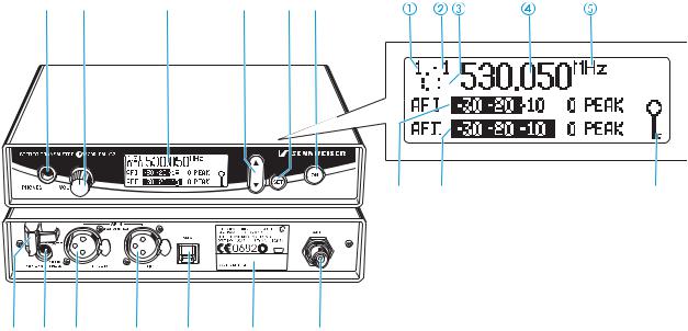
Graphic display panel
Display for the current channel bank “1...8, U”
Display for the current channel number “1...12”
“B.CH“ – abbreviation for channel bank and channel number
Alphanumeric display
“MHz“ – appears when the frequency is displayed
Level display for audio signal “AF I” (left and MONO), with “PEAK” warning
Level display for audio signal “AF II” (right), with “PEAK” warning
Lock mode icon
(lock mode is activated)
Note:
For further illustrations and examples of the different standard displays, please refer to the section “Selecting the standard display“ on page 65.
44
EK 300 IEM G2 stereo receiver
|
|
|
|
|
|
|
|


|
|
|
|
|
|
|
|
|
|
|
|
|
|
|
|
|
|
Operating controls
Headphone output (PHONES), 3.5 mm jack socket
Antenna
Red LED for operation and
battery status indication (ON/LOW BAT)
Green LED for RF signal indication (RF)
SET button
/ rocker button (DOWN/UP)
Battery compartment
Battery compartment cover
Unlocking button
ESC button
LC display
On/off/volume control
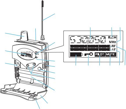
LC display panel
Alphanumeric display
“B.CH“ – appears when the channel bank and the channel number are displayed
“MHz“ – appears when the frequency is displayed
4-step battery status display
Lock mode icon
(lock mode is activated)
“PILOT” display
(pilot tone evaluation is activated)
“MUTE” display
(audio output is muted)
7-step level display for received audio signal “AF”
7-step level display for received RF signal “RF”
45
Indications and displays on the transmitter
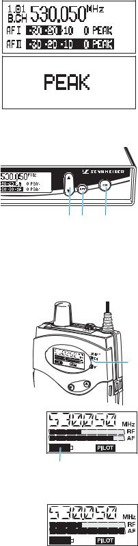
Modulation display
The level display for audio signal “AF” shows the modulation of the transmitter.
When the transmitter’s audio input level is excessively high, the level display for audio signal “AF” shows full deflection.
When the transmitter is overmodulated frequently or for an extended period of time, the text “PEAK” (backlit in red) flashes in alternation with the standard display.
Button backlighting
During standby operation, the ON button is backlit in red. When the transmitter is switched on, the SET button and the / button are additionally backlit in green.
Indications and displays on the receiver
Operation and battery status indication
The red LED (LOW BAT/ON) provides information on the current operating state of the receiver:
Red LED lit up: |
The receiver is switched on and the capacity of the |
|
batteries/accupack BA 2015 is sufficient. |
Red LED flashing: |
The batteries are/the accupack BA 2015 is going flat |
|
(LOW BAT)! |
In addition, the 4-step battery status display on the display panel provides information on the remaining battery/accupack BA 2015 capacity:
|
3 segments: |
capacity approx. 100 % |
2 segments: |
capacity approx. 70 % |
1 segment: |
capacity approx. 30 % |
Battery icon flashing: |
LOW BAT |
Modulation display of the receiving transmitter
The level display for audio signal “AF” shows the modulation of the transmitter.
When the transmitter’s audio input level is excessively high (AF peak), the receiver’s level display for audio signal “AF” shows full deflection.
46

|
“MUTE” display
The “MUTE” display appears on the display panel when the RF signal of the received transmitter is too weak.
|
“PILOT” display
The “PILOT” display appears on the display panel when the pilot tone evaluation is activated (see “Activating/deactivating the pilot tone evaluation (receiver only)” on page 66).
RF signal indication
The green LED (RF) at the front of the receiver lights up when an RF signal is being received.
However, the green LED (RF) does not light up when the audio output is muted because
y the RF signal of the received transmitter is too weak,
 y the transmitter is set to mono operation and the receiver’s pilot tone
  evaluation is activated.
Display backlighting
After pressing a button, the display remains backlit for approx. 15 seconds.
47
Preparing the components for use
SR 300 IEM G2 stereo transmitter
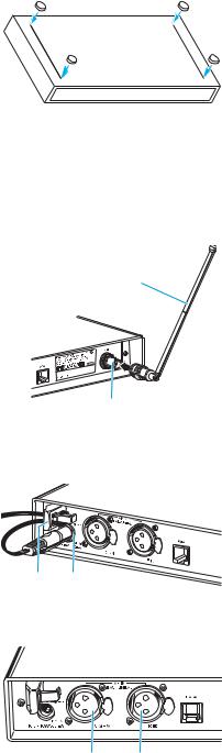
Mounting the transmitter feet
To ensure that the transmitter cannot slip on the surface on which it is placed, four self-adhesive soft rubber feet are supplied.
Ensure that the base of the transmitter is clean and free from grease before mounting the rubber feet.
Fix the rubber feet to the base of the transmitter by peeling of the safety paper and fitting them as shown in the digram on the left.
Attention!
Some furniture surfaces have been treated with varnish, polish or synthetics which might cause stains when they come into contact with other synthetics. Despite a thorough testing of the synthetics used by us, we cannot rule out the possibility of staining.
Connecting the antenna
The supplied telescopic antenna can be mounted quickly and easily to the rear of the transmitter and is suitable for all applications where – good
transmission conditions provided – a wireless transmission system is to be used without a large amount of installation work.
Connect the telescopic antenna to the BNC socket at the rear of the transmitter.
Pull the end cap to extend the telescopic antenna .
Use a remote antenna (available as an accessory) when the transmitter position is not the best antenna position for optimum transmission.
Connecting the mains unit
The transmitter is powered via a mains unit.
Pass the cable through the cable grip .
Insert the DC connector on the mains cable into the DC socket .
Connecting the amplifier/mixing console
Connect the amplifier/mixing console to the XLR-3F sockets (left and MONO) or (right).
Both balanced and unbalanced connection is possible (see “Connector assignment” on page 73).
Note:
Any unit that is only suitable for mono operation must be connected to XLR-3F socket . In this case, set the transmitter to mono operation via the menu.
48
Via the “Sensitiv” menu, adjust the transmitter’s input sensitivity (see “Adjusting the sensitivity (transmitter only)” on page 64).
Connecting the headphones/monitoring the audio signal


 Neue
Neue Abbildung

To monitor the audio signal, connect headphones with a ¼” (6.3 mm) jack plug to the headphone output (PHONES) .
Attention! High volume!
Even short exposure to high volume levels will damage your hearing! Set the volume for the connected headphones to the minimum before putting the headphones on.
First, set the volume control ! to the lowest volume by turning it to the left as far as possible. Then gradually turn up the volume.
Volume up? – NO!
When people use headphones, they tend to choose a higher volume than with loudspeakers. Listening at high volume levels for long periods can lead to permanent hearing defects. Please protect your hearing, Sennheiser headphones have an excellent sound quality even at low volumes.
Service interface
The service interface is only required for servicing purposes.
|
|
|
19” rack adapter and antenna mount |
# |
" |
$ |
For mounting one or two transmitters into a 19” rack, you require the GA 2 |
|
|
|
rack adapter (available as an accessory). The GA 2 rack adapter consists of: |
|
|
|
y 2 rack mount “ears” " |
|
|
|
y 1 connecting bar # |
|
|
|
y 1 connecting plate $ |
|
|
|
y 2 covering plugs % for antenna holes |
y 12 recessed head screws M 3x6
%y 2 recessed head screws M 6x10
When mounting only one transmitter into a rack, you can use the AM 2 antenna mount (available as an accessory) to mount the transmitter’s
antenna connection to the front of the GA 2 rack adapter. The AM 2 antenna mount consists of:
& |
y 2 BNC extension cables (screw-in BNC socket & to BNC connector ') |
|
y 2 plains washers |
' |
y 2 nuts |
49
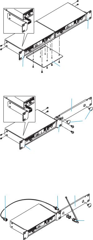
To mount two transmitters into a rack:
Place the two transmitters side by side onto a flat
|
|
surface, their bottom sides facing upwards. |
|
|
Align the connecting plate $ over the holes in the |
|
|
bottom sides of the transmitters. |
|
|
" |
|
|
Secure the connecting plate $ using eight of the |
|
|
supplied recessed head screws (M 3x6). |
|
|
Hook the two rack mount “ears” "to the front panels |
|
|
of the transmitters. |
|
|
Secure the rack mount “ears” to the transmitters |
" |
$ |
using two of the supplied recessed head screws |
(M 3x6) respectively. |
Slide the transmitters into the 19” rack.
Secure the rack mount “ears” to the rack.
#When mounting only one transmitter into a rack, use the
|
|
|
connecting bar # instead of the second transmitter. |
|
|
|
Hook the two rack mount “ears” "to the front panels |
|
|
|
of the transmitter. |
|
|
% |
Secure the rack mount “ears” to the transmitter using |
|
|
|
two of the supplied recessed head screws (M 3x6) |
|
" |
|
respectively. |
|
|
Secure the connecting bar #to one of the rack mount |
|
|
|
|
|
|
|
|
“ears” " using two of the supplied recessed head |
|
" |
|
screws (M 6x10). |
|
|
|
|
|
|
|
If you are not front mounting the antennas, insert the |
|
|
|
two covering plugs % into the antenna holes of the |
|
|
|
connecting bar. |
|
|
|
Slide the transmitter into the 19” rack. |
|
|
|
Secure the rack mount “ears” to the rack. |
' |
& |
# |
To mount the transmitter’s antenna connection to the |
|
|
|
front of the GA 2 rack adapter using the AM 2 antenna |
|
|
|
mount: |
|
|
|
Screw the BNC socket & of the BNC extension cables |
|
|
|
to the connecting bar # using the supplied plain |
|
|
|
washer and nut. |
|
|
|
Connect the BNC connector ' to the BNC socket at |
|
|
|
the rear of the transmitter. |
|
|
|
Slide the transmitter into the 19” rack. |
Secure the rack mount “ears” to the rack.
Connect the telescopic antenna to the BNC socket &.
Pull the end cap to extend the telescopic antenna.
50
Loading...