


EW100-G4-ME3
evolution wireless G4
100 series
Instruction Manual
Sennheiser electronic GmbH & Co. KG
Am Labor 1, 30900 Wedemark, Germany, www.sennheiser.com
ew 100 G4 - v2.0

1
Overview 6
ew 100 G4 series products 7
EM 100 G4 rack receiver 8
SKM 100 G4 handheld transmitter 9
SK 100 G4 bodypack transmitter 10
Accessories 11
Microphones and cables 12
Microphone modules 12
Headset and Lavalier microphones 12
Line/instrument cables 13
Rechargeable battery and charger 14
BA 2015 rechargeable battery 14
L 2015 charger 14
LA 2 charging adapter 15
Accessories for rack mounting 16
GA 3 rack mount kit 16
AM 2 antenna front mounting kit 16
Antennas and accessories 17
Omni-directional antennas 17
Directional antennas 17
Antenna splitter 17
Antenna amplifiers 17
Antenna cables 17
Additional accessories 18
Color labeling set 18
Microphone clamp 18
The frequency bank system 19
Installing and starting up ew 100 G4 series devices
20
Installing the EM 100 G4 21
Connectors on the rear of the device 22
Product overview for the rear side of the EM 100 G4 22
Connecting/disconnecting the EM 100 G4 to/from the
power supply system 23
Creating a data network 24
Setting up a multi-channel system with more than 12
receivers 25
Outputting audio signals 26
Connecting antennas 27
Installing the EM 100 G4 in a rack 28
Mounting a single receiver in a rack 29
Mounting two receivers side by side in a rack 30
Installing the SKM 100 G4 31
Inserting and removing the batteries/rechargeable bat-
teries 32
Battery status 33
Replacing the microphone module 34
Changing the colored ring 35
Installing the SK 100 G4 36
Inserting and removing the batteries/rechargeable bat-

2
teries 37
Battery status 38
Connecting a microphone to the SK 100 G4 39
Connecting an instrument or line source to the SK 100 G4
40
Attaching the bodypack transmitter to clothing 41
Installing the ASA 214 42
Connectors on the rear of the device 43
Product overview for the rear side of the ASA 214 43
Connecting/disconnecting the ASA 214 to/from the po-
wer supply system 44
Connecting receivers to the ASA 214 45
Connecting antennas 47
Connecting remote antennas 47
Connecting rod antennas 47
Information on antenna amplifiers and cable lengths 48
Configuring multi-channel systems 50
Option 1: Two antennas supply a 4-channel system 50
Option 2: Two 4-channel systems are interconnected
51
Option 3: Two antennas supply a 8-channel system 51
Installing the ASA 214 in a rack 52
Mounting a single antenna splitter in a rack 53
Mounting two antenna splitters side by side in a rack
55
Using ew 100 G4 series devices 56
Using the EM 100 G4 58
Operating elements on the front of the device 59
Product overview for the front of the EM 100 G4 59
Switching the EM 100 G4 on and off 60
Muting the audio output 61
Lock-off function 62
Displays on the EM 100 G4 display panel 63
Buttons for navigating through the menu 63
Home screen 65
Receiver Parameters standard display 65
Soundcheck standard display 66
RF Min 66
RF Max 67
AF Max 67
Guitar Tuner standard display 67
Setting options in the menu 68
Menu structure 69
Squelch menu item 70
Easy Setup menu item 72
Scan New List 72
Current List 73
Reset 73
Performing multi-channel frequency setup 73
Setting up a multi-channel system with more than 12
receivers 75

3
Frequency Preset menu item 76
Name menu item 77
AF Out menu item 78
Equalizer menu item 79
Auto Lock menu item 80
Advanced menu item 81
Advanced -> Tune menu item 82
Only adjusting the frequency 82
Setting the channel and frequency 82
Advanced -> Guitar Tuner menu item 83
Advanced -> Pilot Tone menu item 83
Advanced -> LCD Contrast menu item 84
Advanced -> Reset menu item 84
Advanced -> Software Revision menu item 84
Using the SKM 100 G4 85
Operating elements of the SKM 100 G4 handheld trans-
mitter 86
Switching the SKM 100 G4 handheld transmitter on and
off 87
Muting the handheld transmitter (AF mute) 88
SKM 100 G4 88
SKM 100 G4-S 88
Deactivating the RF signal (RF mute) 89
Lock-off function 90
Displays on the SKM 100 G4 handheld transmitter dis-
play panel 91
Select a standard display 92
Buttons for navigating the SKM 100 G4 menu 93
Navigating through the menu 93
Making changes in a menu item 93
Setting options in the menu 94
Sensitivity menu item 95
Frequency Preset menu item 96
Name menu item 96
Auto Lock menu item 97
Advanced menu item 98
Advanced > Tune menu item 99
Only adjusting the frequency 99
Setting the channel and frequency 99
Advanced > Mute Mode menu item (SKM 100 G4-S only)
100
Advanced > Pilot Tone menu item 100
Advanced > LCD Contrast menu item 100
Advanced > Reset menu item 101
Advanced > Software Revision menu item 101
Using the SK 100 G4 102
Operating elements of the SK 100 G4 bodypack transmit-
ter 103
Switching the SK 100 G4 bodypack transmitter on and off
104
Muting the bodypack transmitter (AF mute) 105

4
Deactivating the RF signal (RF mute) 106
Deactivating the RF signal with the MUTE switch 106
Deactivating the RF signal with the ON/OFF button 108
Lock-off function 109
Displays on the SK 100 G4 bodypack transmitter display
panel 110
Select a standard display 111
Buttons for navigating the SK 100 G4 menu 112
Navigating through the menu 112
Making changes in a menu item 112
Setting options in the menu 113
Sensitivity menu item 114
Frequency Preset menu item 114
Name menu item 115
Auto Lock menu item 115
Advanced menu item 116
Advanced > Tune menu item 117
Only adjusting the frequency 117
Setting the channel and frequency 117
Advanced > Mute Mode menu item 118
Advanced > Cable Emulation menu item 118
Advanced > Pilot Tone menu item 119
Advanced > LCD Contrast menu item 119
Advanced > Reset menu item 119
Advanced > Software Revision menu item 119
Establishing a radio link 120
Setting notes 120
Synchronizing devices 121
Using the ASA 214 123
Operating elements on the front of the device 124
Switching the ASA 214 on and off 125
Overview 126
Product variants 127
EM 100 G4 product variants 127
Made in Germany 127
Assembled in the USA 127
SKM 100 G4 product variants 128
Made in Germany 128
Assembled in the USA 128
SK 100 G4 product variants 129
Made in Germany 129
Assembled in the USA 129
Frequency tables 130
Specifications 131
EM 100 G4 132
RF characteristics 132
AF characteristics 133
Overall device 133
SKM 100 G4 134
RF characteristics 134

5
AF characteristics 134
Overall device 135
SK 100 G4 136
RF characteristics 136
AF characteristics 136
Overall device 137
ASA 214 138
Specifications 138
Block diagram 139
Pin assignment 140
3.5 mm stereo jack plug 140
3.5 mm mic jack plug 140
3.5 mm line jack plug 140
6.3 mm stereo jack plug, balanced (audio in/loop out)
140
6.3 mm mono jack plug, unbalanced 141
6.3 mm stereo jack plug for headphone jack 141
XLR-3 plug, balanced 141
Hollow jack plug for power supply 141
Cleaning and maintenance 142
Cleaning the sound inlet basket of the microphone mo-
dule 142
Overview
6
PRODUCT INFORMATION
Overview
You can find information about the individual products in the ew 100 G4 se-
ries under “ew 100 G4 series products”.
For information about the available accessories, see “Accessories”.
You can find information about the ew 100 G4 series frequency bank sys-
tem under “The frequency bank system”.

ew 100 G4 series products
7
ew 100 G4 series products
You can also find more information here:
• A variety of frequency variants are available from the individual prod-
ucts. You can find more information under “Product variants”.
•You can find technical specifications about the individual products un-
der “Specifications”.
• You can find information about installing the products under “Installing
and starting up ew 100 G4 series devices”.
• You can find information about operating the products under “Using
ew 100 G4 series devices”.
8
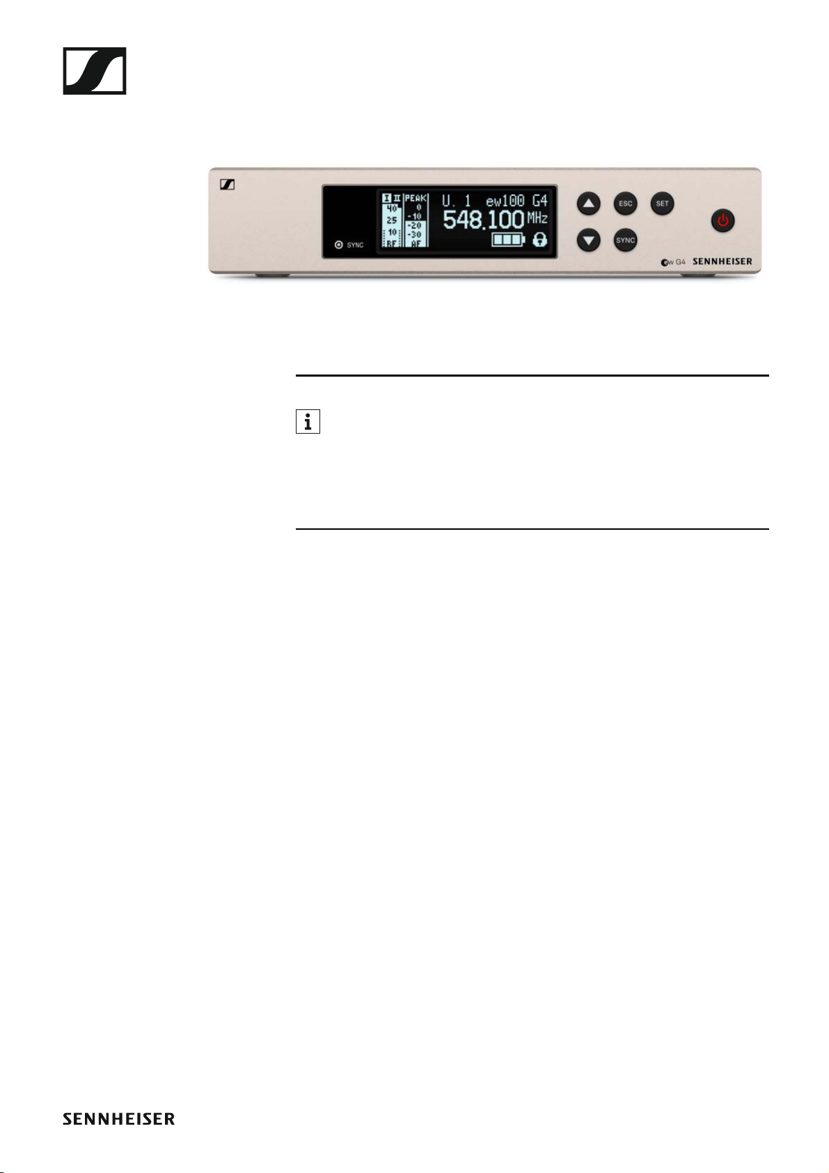
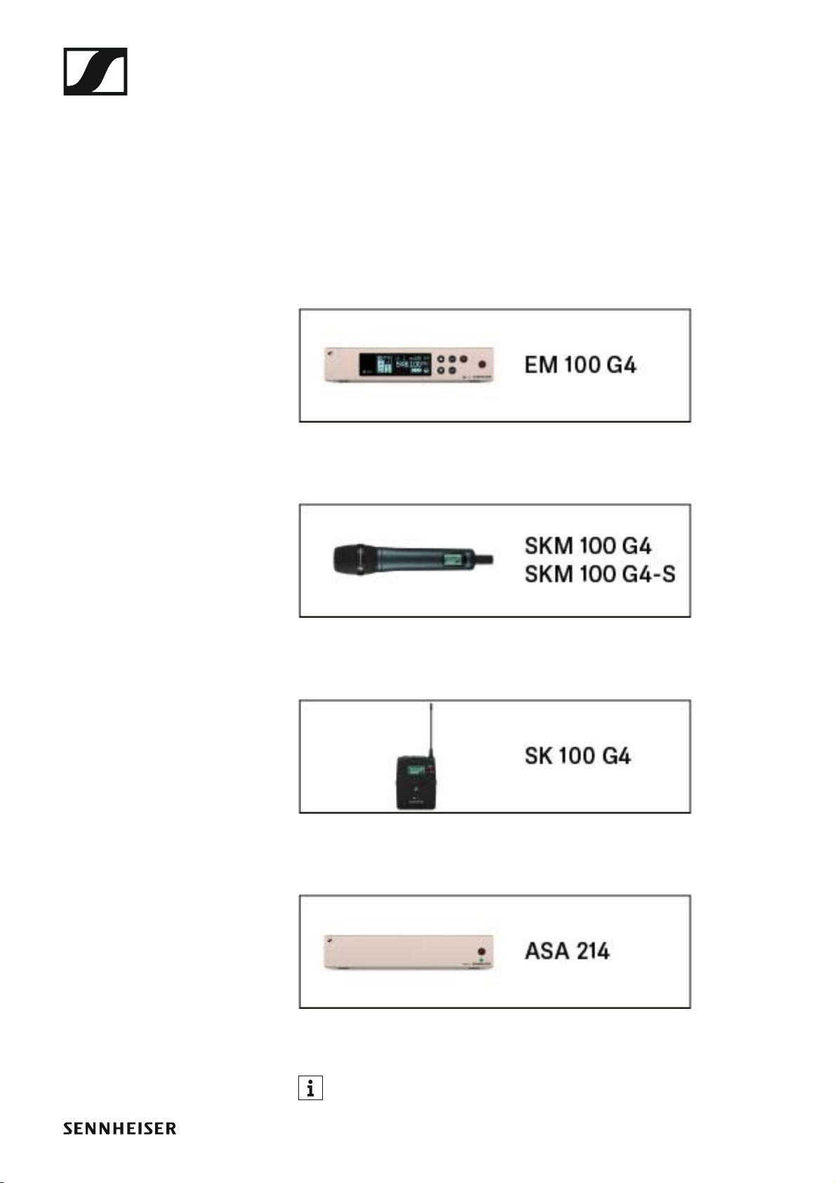
EM 100 G4 rack receiver
►
You can find more detailed information about the EM 100 G4 in the
following sections:
• Installation and Startup: “Installing the EM 100 G4”
• Operation: “Using the EM 100 G4”
• Technical Data: “EM 100 G4”
9
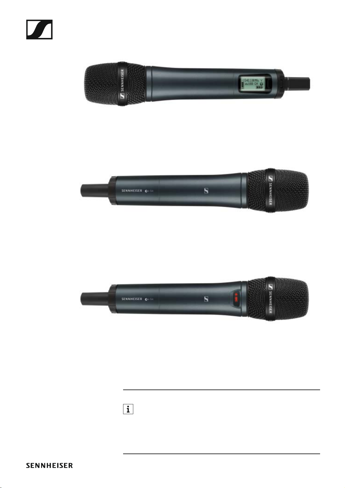
SKM 100 G4 handheld transmitter
►
SKM 100 G4 variant:
►
SKM 100 G4-S variant:
►
The SKM 100 G4 handheld transmitter is also available in the SKM 100 G4-
S variant with an integrated mute switch.
You can find more detailed information about the SKM 100 G4 in the
following sections:
• Installation and Startup: “Installing the SKM 100 G4”
• Operation: “Using the SKM 100 G4”
• Technical Data: “SKM 100 G4”

10
SK 100 G4 bodypack transmitter
►
You can find more detailed information about the SK 100 G4 in the
following sections:
• Installation and Startup: “Installing the SK 100 G4”
• Operation: “Using the SK 100 G4”
• Technical Data: “SK 100 G4”

Accessories
11
Accessories
A variety of accessories are available for the ew 100 G4 series.

Accessories
12
Microphones and cables
Microphone modules
We recommend using the following microphone modules with the
SKM 100 G4 and SKM 100 G4-S handheld transmitters.
►
You can find more information about the individual microphone mod-
ules on their respective product pages at www.sennheiser.com.
Headset and Lavalier microphones
We recommend using the following Lavalier microphones and headset mi-
crophones with the SK 100 G4 bodypack transmitter.
►
Module Features Article
no.
MMD 835-1 BK Dynamic, cardioid, black 502575
MMD 845-1 BK Dynamic, super-cardioid, black 502576
MME 865-1 BK Capacitor, super-cardioid, black 502581
MMD 935-1 BK Dynamic, cardioid, black 502577
MMD 945-1 BK Dynamic, super-cardioid, black 502579
MMK 965-1 BK Capacitor, switchable
Cardioid/super-cardioid, black
502582
MMK 965-1 NI Capacitor, switchable
Cardioid/super-cardioid, nickel
502584
MMD 42-1 Dynamic, omni-directional, black 506772
Microphone Features Article
no.
ME 2-II Lavalier microphone, omni-direc-
tional, black
507437
ME 3-II Headset microphone, cardioid,
black
506295
ME 4-N Lavalier microphone, cardioid,
black
005020
MKE 1-ew Lavalier microphone, omni-direc-
tional, black
502876
MKE 1-ew-3 Lavalier microphone, omni-direc-
tional, beige
502879
MKE 2-ew Gold Lavalier microphone, omni-direc-
tional, black
009831
MKE 2 ew-3 Gold Lavalier microphone, omni-direc-
tional, beige
009832
MKE 40-ew Lavalier microphone, cardioid,
black
500527
Accessories
13
You can find more information about the individual microphones on
their respective product pages at www.sennheiser.com.
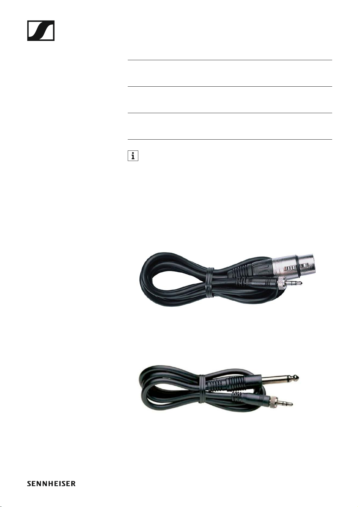
Line/instrument cables
The following cables are available to connect instruments and line sources
to the SK 100 G4 bodypack transmitter:
• Sennheiser CL 2
Line cable with XLR-3F plug on lockable 3.5 mm jack plug, article no.
004840
►
• Sennheiser Ci 1-N
Guitar cable with 6.3 mm jack plug on lockable 3.5 mm jack plug, article
no. 005021
►
SL Headmic 1 BE Headband microphone, omni-di-
rectional,
beige
506272
SL Headmic 1 BK Headband microphone, omni-di-
rectional,
black
506271
SL Headmic 1 SB Headband microphone, omni-di-
rectional,
silver
506904
Microphone Features Article
no.
Accessories
14
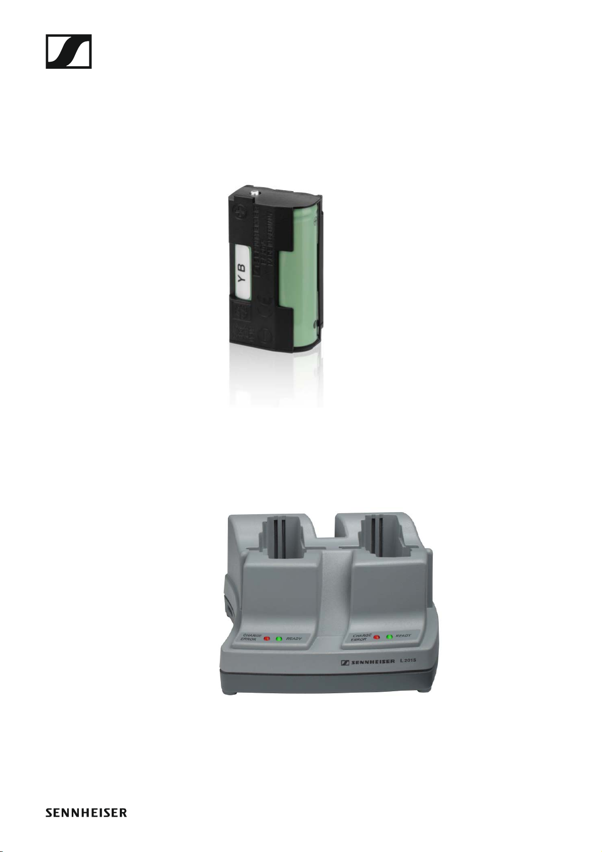
Rechargeable battery and charger
BA 2015 rechargeable battery
The BA 2015 rechargeable battery is designed for use with evolution wire-
less G4 series handheld transmitters, bodypack transmitters and
bodypack receivers.
Article no. 009950
►
L2015 charger
The BA 2015 rechargeable battery can be charged in the L 2015 charger on
its own or inside of the bodypack transmitter/bodypack receiver.
Article no. 009828
►
Accessories
15
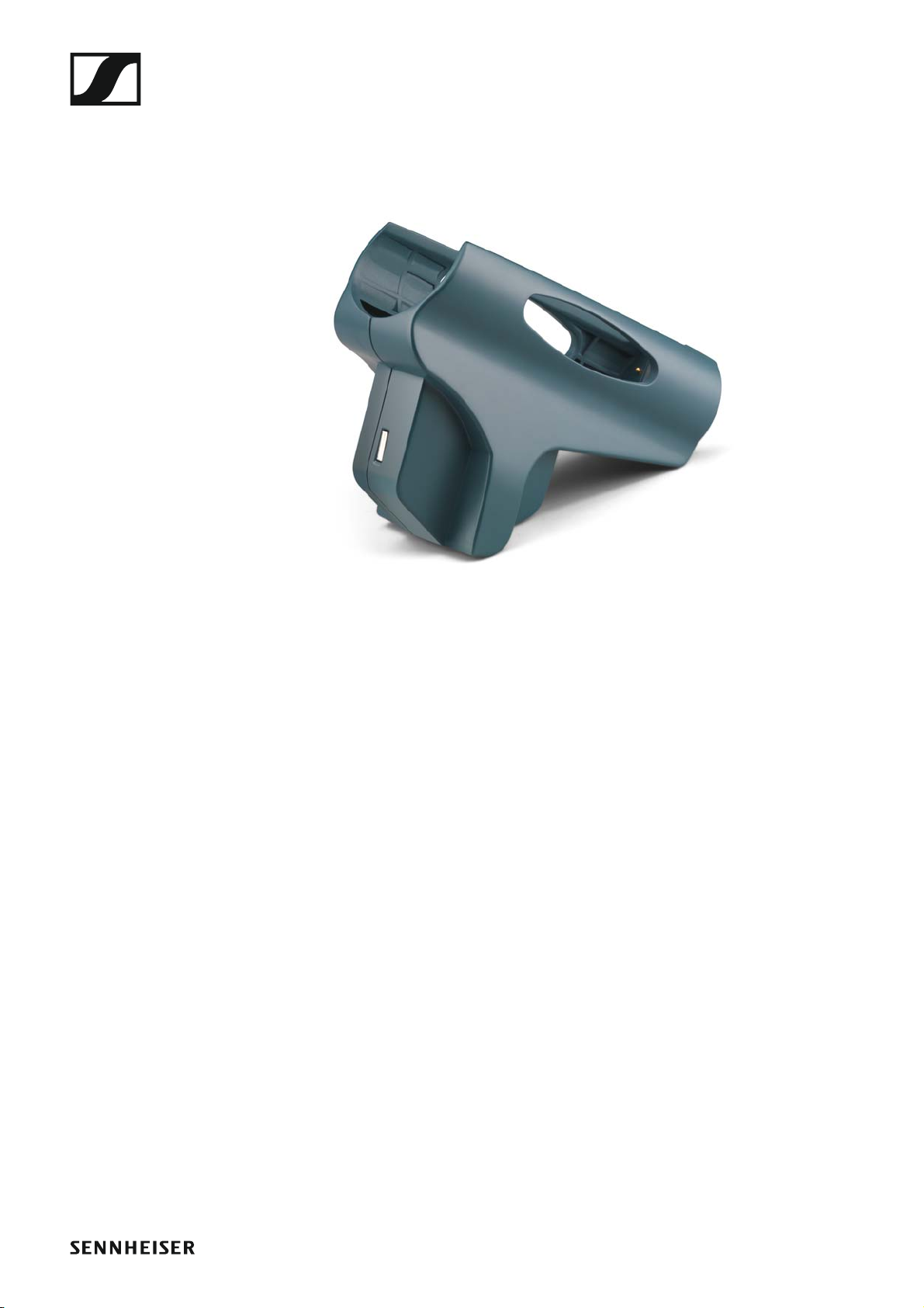
LA 2 charging adapter
Charging adapter for L 2015 charger for charging SKM G4 handheld trans-
mitters with installed BA 2015 rechargeable battery.
Article no. 503162
►
Accessories
16
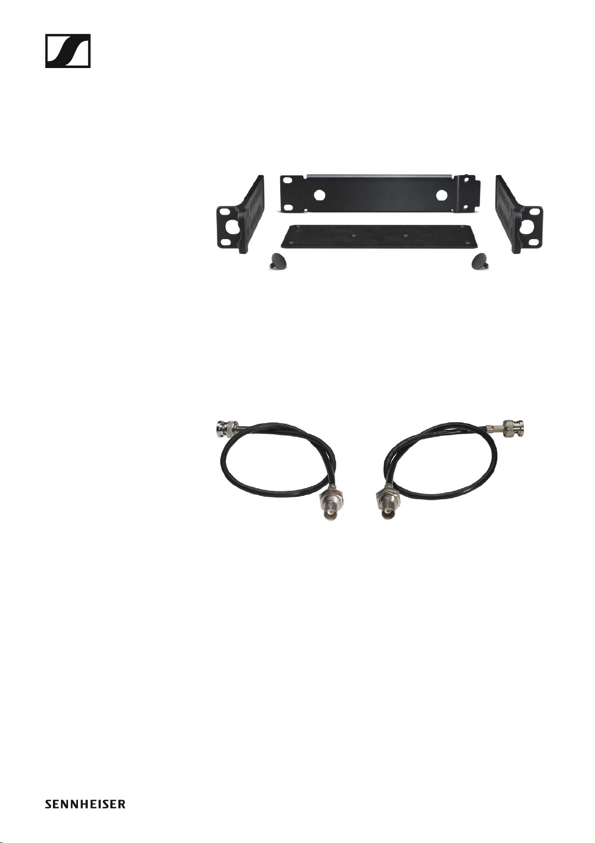
Accessories for rack mounting
GA 3 rack mount kit
19” rack adapter for mounting the EM 100 G4, EM 300-500 G4 or
SR IEM G4 in a 19” rack.
Article no. 503167
►
AM 2 antenna front mounting kit
Antenna front mounting kit for installing antenna connections on the front
of the rack when using the EM 100 G4, EM 300-500 G4 or SR IEM G4 to-
gether with the GA 3 rack mounting kit.
Article no. 009912
►
►
Accessories
17
Antennas and accessories
The following antenna components are available as accessory parts.
Omni-directional antennas
• A 1031-U, passive omni-directional antenna, article no. 004645
Directional antennas
• A 2003 UHF, passive directional antenna, article no. 003658
• AD 1800, passive directional antenna, 1.8 GHz range, article no. 504916
Antenna splitter
►
• ASA 214, active antenna splitter 2×1:4
• ASA 214-UHF variant, 470 – 870 MHz, article no. 508241
• ASA 214-1G8 variant, 1785 – 1800 MHz, article no. 508242
• See “Installing the ASA 214” and “Using the ASA 214”
Antenna amplifiers
• AB 3700, broadband antenna amplifier, article no. 502196
• AB 3, antenna amplifier, up to 42 MHz bandwidth
• AB 3-A variant, frequency range A, article no. 502567
• AB 3-A1 variant, frequency range A1, article no. 507367
• AB 3-B variant, frequency range B, article no. 502568
• AB 3-C variant, frequency range C, article no. 502569
• AB 3-D variant, frequency range D, article no. 502570
• AB 3-E variant, frequency range E, article no. 502571
• AB 3-G variant, frequency range G, article no. 502572
• AB 3-GB variant, frequency range GB, article no. 504680
• AB 3-K variant, frequency range K, article no. 505550
• AB 3-1G8 variant, frequency range 1G8, article no. 504915
Antenna cables
• GZL 1019, BNC/BNC coaxial cable, antenna cable with 50 Ω character-
istic (wave) impedance
• GZL 1019-A1 variant, 1 m (3 ft), article no. 002324
• GZL 1019-A5 variant, 5 m (16 ft), article no. 002325
• GZL 1019-A10 variant, 10 m (32 ft), article no. 002326
Accessories
18
Additional accessories
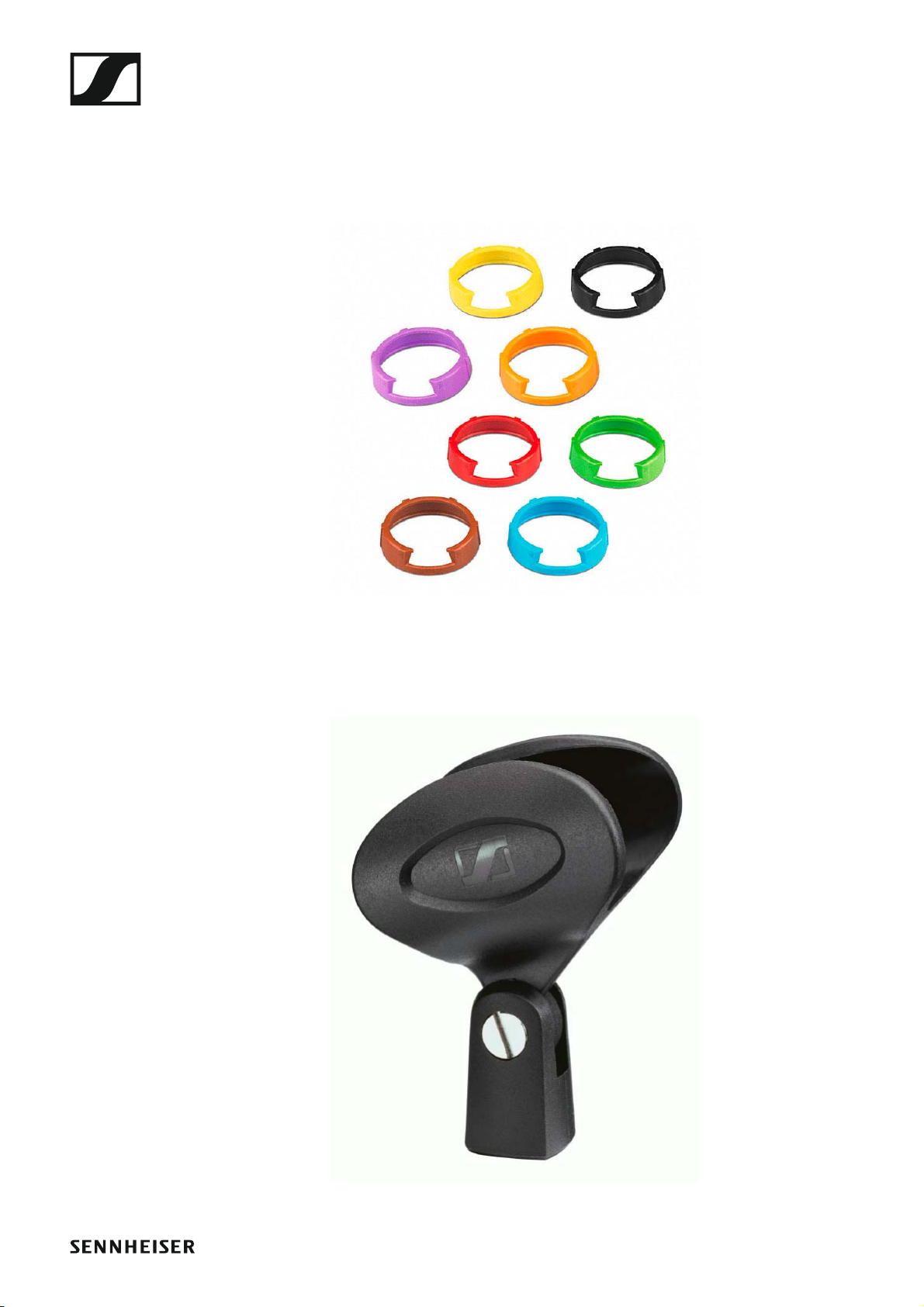
Color labeling set
• KEN 2, color labeling set for SKM handheld transmitters, article no.
530195
►
Microphone clamp
• MZQ 1, microphone clamp for SKM handheld transmitters, article no.
076670
►
The frequency bank system
19
The frequency bank system
There are different frequency ranges in the UHF band available for trans-
mission.
The following frequency ranges are available for the ew 100 G4 series:
• A1 range: 470 – 516 MHz
• A range: 516 – 558 MHz
• AS range: 520 – 558 MHz
• G range: 566 – 608 MHz
• GB range: 606 – 648 MHz
• B range: 626 – 668 MHz
• C range: 734 – 776 MHz
• D range: 780 – 822 MHz
• TH range: 794 – 806 MHz
• JB range: 806 – 810 MHz
• E range: 823 – 865 MHz
• K+ range: 925 – 937.5 MHz
• 1G8 range: 1785 – 1800 MHz
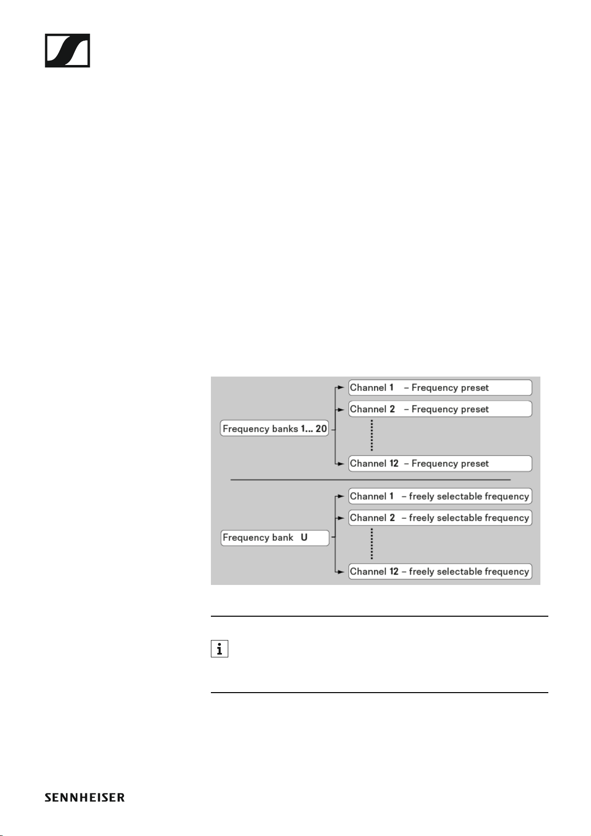
Every frequency range has 21 frequency banks with up to 12 channels:
►
You can find information about the frequency presets in the frequen-
cy tables of the respective frequency ranges under “Frequency ta-
bles”.
Installing and starting up ew 100 G4 series devices
20
INSTALLATION
Installing and starting up ew 100 G4 se-
ries devices
You can find information about installing and connecting ew 100 G4 series
devices in the following sections.
• EM 100 G4 rack receiver >> “Installing the EM 100 G4”
• SKM 100 G4(-S) handheld transmitter >> “Installing the SKM 100 G4”
• SK 100 G4 bodypack transmitter >> “Installing the SK 100 G4”
• ASA 214 antenna splitter>> “Installing the ASA 214”
You can find information about operating the products under “Using
ew 100 G4 series devices”.

Installing the EM 100 G4
21
Installing the EM 100 G4
These sections contain detailed information about installing and starting
up the EM 100 G4.
You can find information about operating the EM 100 G4 under “Using the
EM 100 G4”.

Installing the EM 100 G4
22
Connectors on the rear of the device
Product overview for the rear side of the EM 100 G4
►
1 Strain relief for the cable of the power supply unit
• See “Connecting/disconnecting the EM 100 G4 to/from the power
supply system”
2 Connecting cables for the power supply unit (DC IN)
• See “Connecting/disconnecting the EM 100 G4 to/from the power
supply system”
3 XLR-3 socket for audio output, balanced (AF OUT BAL)
• See “Outputting audio signals”
4 6.3 mm jack socket for audio output, unbalanced (AF OUT UNBAL)
• See “Outputting audio signals”
5 RJ-10 interface (DATA)
• See “Creating a data network”
6 RJ-10 interface (DATA)
• See “Creating a data network”
7 BNC socket, antenna input II (ANT II) with remote power supply unit
• See “Connecting antennas”
8 BNC socket, antenna input I (ANT I) with remote power supply unit
• See “Connecting antennas”
Installing the EM 100 G4
23
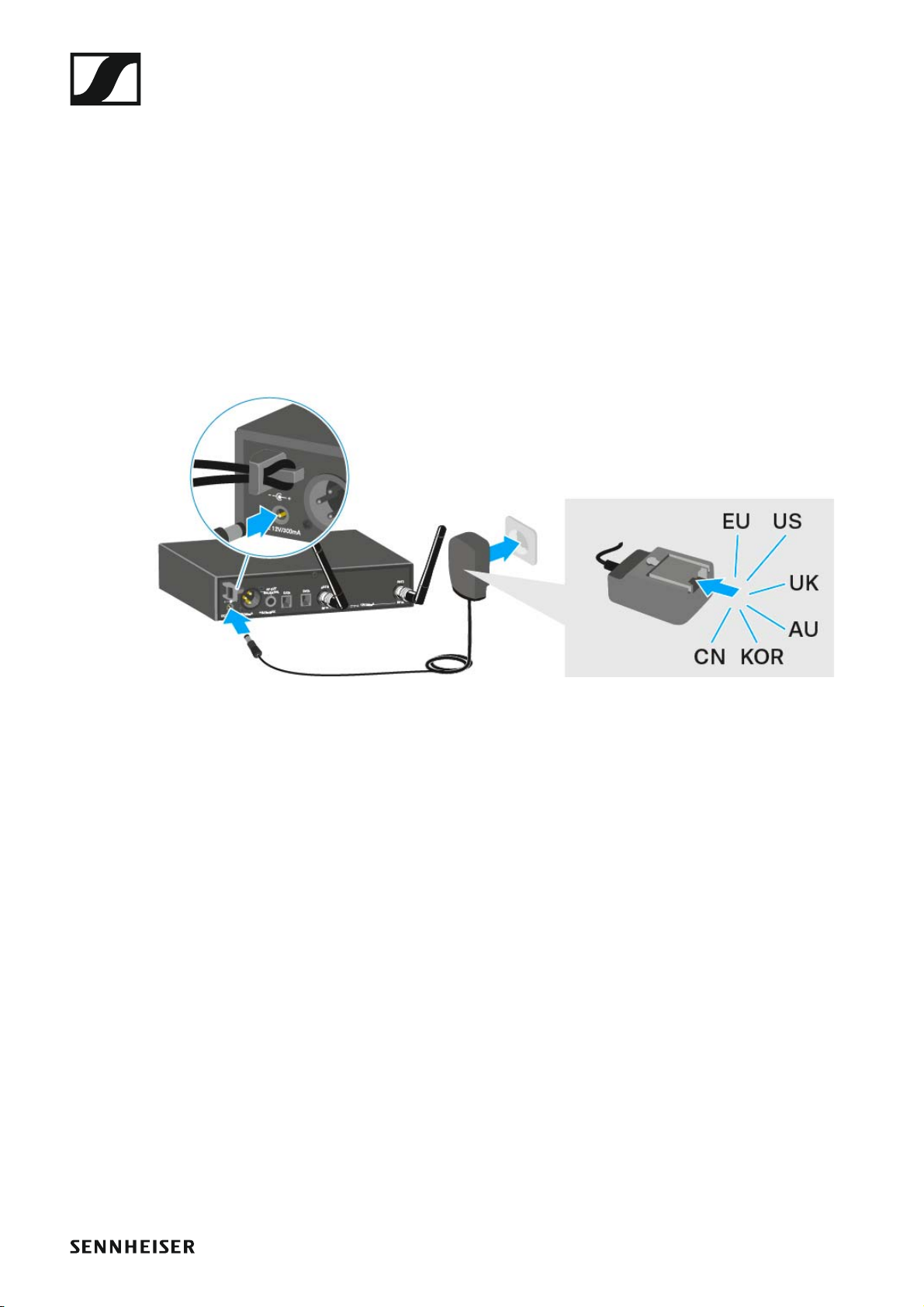
Connecting/disconnecting the EM 100 G4 to/from
the power supply system
Only use the supplied power supply unit. It is designed for your receiver
and ensures safe operation.
To connect the EM 100 G4 to the power supply system:
▷ Insert the plug of the power supply unit into the DC IN socket of the re-
ceiver.
▷ Pass the cable of the power supply unit through the cable grip.
▷ Slide the supplied country adapter onto the power supply unit.
▷ Plug the power supply unit into the wall socket.
To completely disconnect the EM 100 G4 from the power supply system:
▷ Unplug the power supply unit from the wall socket.
▷ Unplug the power supply unit from the DC IN socket of the receiver.
Installing the EM 100 G4
24
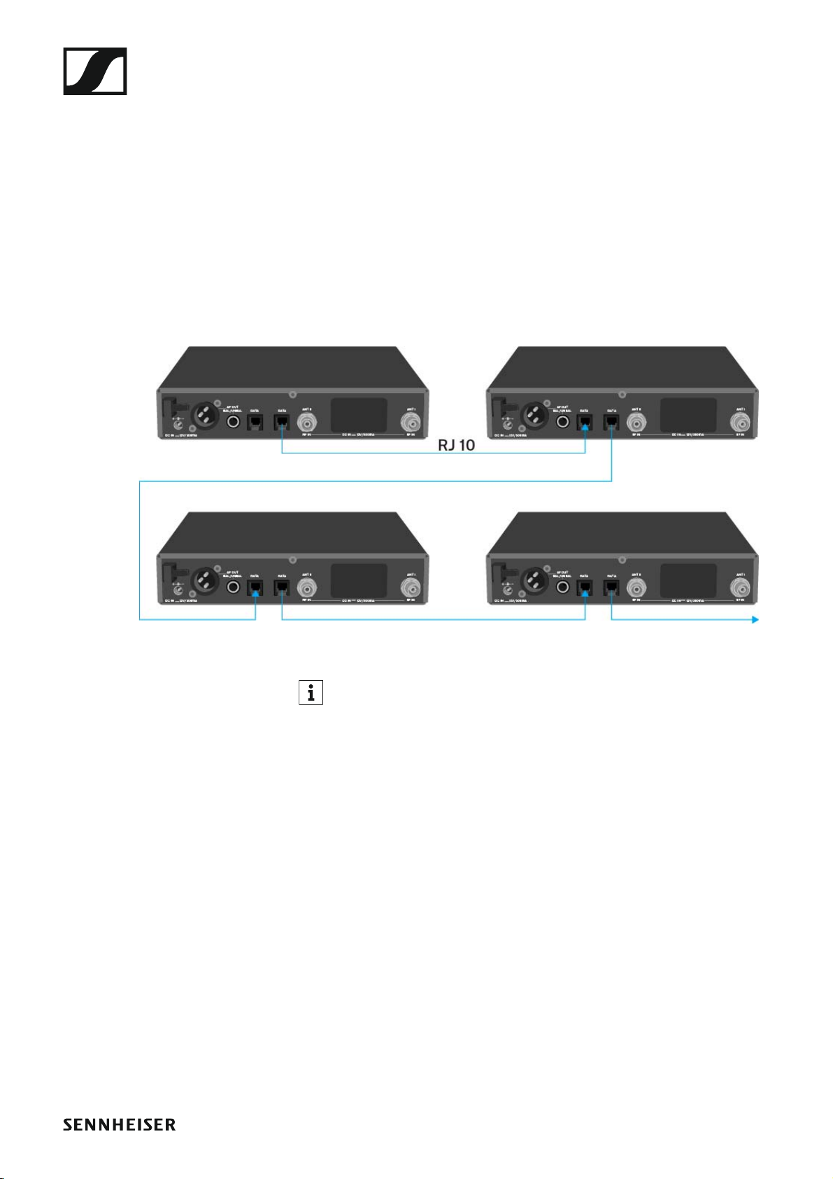
Creating a data network
You can cascade multiple EM 100 G4s to a multi-channel system using the
two DATA RJ-10 interfaces (up to 12 receivers). You can perform a frequen-
cy setup for the entire multi-channel system via this data network using the
Easy Setup function.
The setup only works when all of the receivers have the same frequency
range.
▷ Connect the receivers to create a multi-channel system using the sup-
plied RJ-10 cables as shown in the diagram.
Both RJ-10 sockets are interchangeable. There is no set order for ca-
bling.
►
You can find more information about the Easy Setup function under
“Easy Setup menu item”.
Installing the EM 100 G4
25
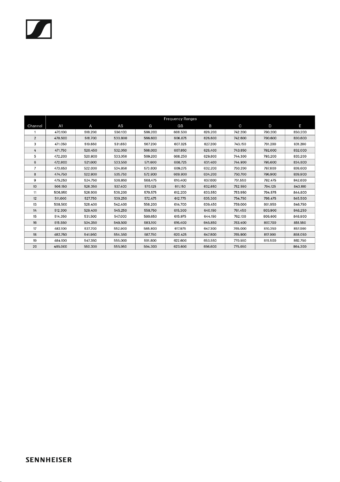
Setting up a multi-channel system with more than 12 receivers
You can use the Easy Setup function to automatically set up a maximum
of 12 receivers.
If you assign the frequencies manually, however, you can use up to 20 re-
ceivers in a multi-channel system (not possible in the TH, JB, K+ and 1G8
frequency ranges).
▷ To do so, set a frequency manually in each receiver (see “Advanced ->
Tune menu item”).
▷ Use the frequencies from the following table.
►
Installing the EM 100 G4
26
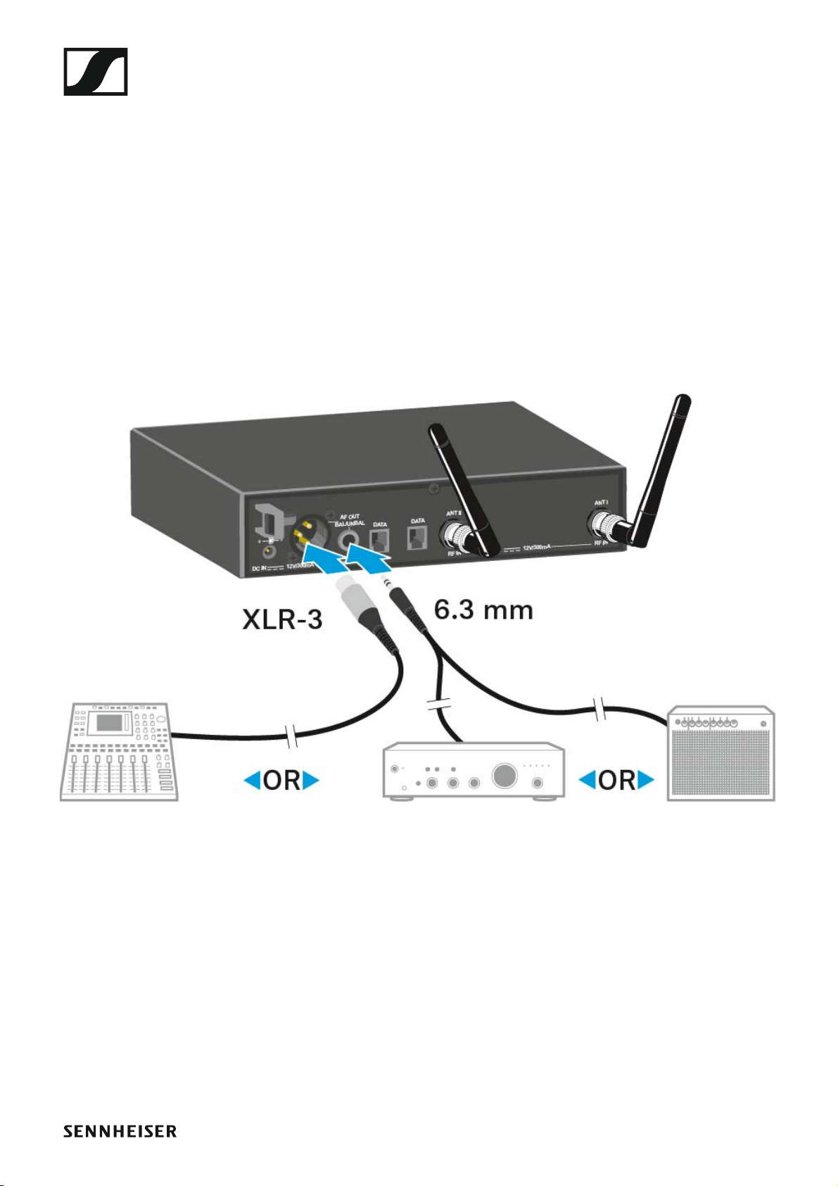
Outputting audio signals
The EM 100 G4 has a balanced XLR-3M output socket and an unbalanced
6.3 mm jack output socket.
▷ Always use only one of the two AF OUT output sockets for each chan-
nel.
To connect an XLR cable:
▷ Plug the XLR cable into the AF OUT BAL socket of the EM 100 G4.
To connect a jack cable:
▷ Plug the jack cable into the AF OUT UNBAL socket of the EM 100 G4.

Installing the EM 100 G4
27
Connecting antennas
To connect the supplied rod antennas:
▷ Connect the first rod antenna to the ANT I socket on the rear side of the
EM 100 G4.
▷ Connect the second rod antenna to the ANT II socket on the rear side
of the EM 100 G4.
▷ Gently angle the rod antennas to the left and right as shown in the fig-
ure.
If you are using more than one receiver, we recommend using remote
antennas and the ASA 214 antenna splitter. You can find more infor-
mation here:
•“Installing the ASA214”
•“Using the ASA214”

Installing the EM 100 G4
28
Installing the EM 100 G4 in a rack
CAUTION
Rack mounting poses risks
When installing the device in a closed or multi-rack assembly, please con-
sider that, during operation, the ambient temperature, the mechanical
loading and the electrical potentials will be different from those of devices
which are not mounted into a rack.
▷ Make sure that the ambient temperature within the rack does not ex-
ceed the permissible temperature limit specified in the specifications.
See “EM 100 G4”.
▷ Ensure sufficient ventilation; if necessary, provide additional ventila-
tion.
▷ Make sure that the mechanical loading of the rack is even.
▷ When connecting to the power supply system, observe the information
indicated on the type plate. Avoid circuit overloading. If necessary, pro-
vide overcurrent protection.
▷ When rack mounting, please note that intrinsically harmless leakage
currents of the individual power supply units may accumulate, thereby
exceeding the allowable limit value. As a remedy, ground the rack via
an additional ground connection.
Installing the EM 100 G4
29
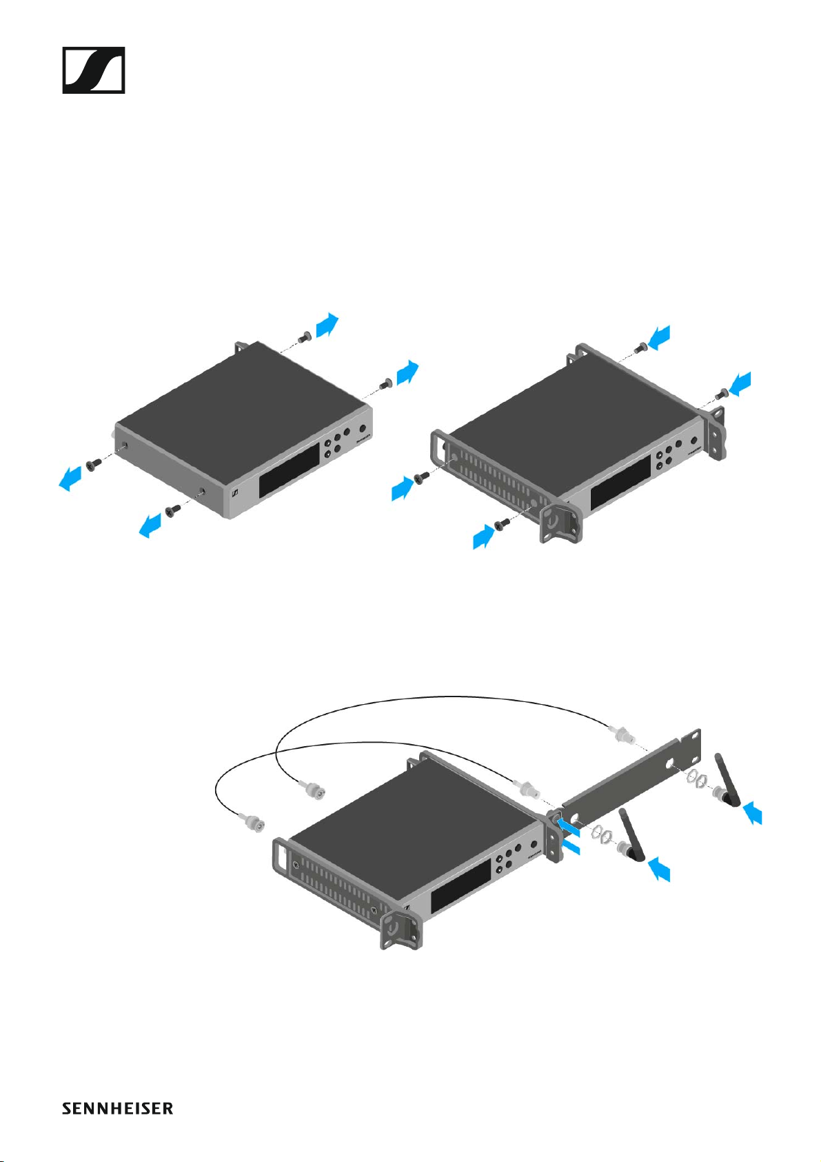
Mounting a single receiver in a rack
To mount the receiver in a rack, you will need the GA 3 rack mounting kit
(optional accessory).
To fasten the mounting angle of the GA 3 rack mounting kit:
▷ Unscrew and remove the two recessed head screws (M4x8) on each
side of the receiver.
▷ Secure both of the the mounting angles to the sides of the receiver us-
ing the previously removed recessed head screws.
►
▷ Secure the blanking plate to one of the mounting angles using two re-
cessed head screws (M6x10).
▷ Attach the AM 2 antenna front mounting set (optional accessory) and
mount the rod antennas on the blanking plate (right diagram).
►
▷ Slide the receiver with the mounted blanking plate into the 19" rack.
▷ Secure the mounting angle and the blanking plate to the 19" rack.
▷ Align the mounted antennas in a V-shape.
 Loading...