


Service
EM 3031-U EM 3032-U EM 3532-U EM 3031-V EM 3032-V
(Art.-Nr. / Cat no. 04555)
(Art.-Nr. / Cat no. 04556)
(Art.-Nr. / Cat no. 04400)
(Art.-Nr. / Cat no. 04365)
(Art.-Nr. / Cat no. 04201)
Sennheiser electronic GmbH & Co. KG • D-30900 Wedemark • Tel. 0 51 30 / 600-0 |
EM 3031, 3032, 3532 |
Änderungen vorbehalten / Subject to alterations / Sous réserve de modification |
07 / 98 - 1 |
Deutsch
!DVE
English
!DVE
Italiano
!DVE
Français
!DVE
Español
!DVE
USA &
Canada
!


!DVE
Sicherheitsvorschriften/Safetyrequirements/ Prescrizioni de sicurezza / Prescriptions de sécurité / Prescripciones de seguridad
Achtung: Bei Eingriffen in das Gerät sind die Sicherheitsvorschriften nach VDE 701 (reparaturbezogen) bzw. VDE 0860 / IEC 65 (gerätebezogen) zu beachten !
Bauteile nach IECbzw. VDE-Richtlinien ! Im Ersatzfall nur Teile mit gleicher Spezifikation verwenden !
MOS - Vorschriften beim Umgang mit MOS - Bauteilen beachten !
Attention: Please observe the applicable safety requirements according to VDE 701 (concerning repairs) and VDE0860 / IEC 65 (concerning type of product) !
Components to IEC or VDE guidelines ! Only use components with the same specifications for replacement !
Observe MOS components handling instructions when servicing !
Attenzione: Osservarne le corrispondenti prescrizioni di sicurezza VDE 701 (concernente servizio) e VDE 0860 / IEC 65 (concernente il tipo di prodono) !
Componenti secondo le norme VDE risp. te IEC ! In caso di sostituzione impiegare solo componenti con le stesse caratteristiche.
Osservare le relative prescrizioni durante, lavori con componenti MOS !
Attention:Prière d‘observer les prescriptions de sécurité VDE701 (concernant les réparations) et VDE 0860 / IEC 65 (concernant le type de produit) !
Composants répondant aux normes VDE ou IEC. Les remplacer uniquement par des composants ayant les memes spécifications.
Lors de la manipulation des circuits MOS, respecter les prescriptions MOS !
Atención: Recomendamos las normas de seguridad VDE u otras normas equivalentes, por ejemplo: VDE 701 para reparaciones, VDE 0860 / IEC 65 para aparatos !
Componentes que cumplen las normas VDE / IEC. En caso de sustitución, emplear componentes con idénticas especificaciones !
Durante la reparacion observar las normas sobre componentes MOS !
Attention: This set can only be operated from AC mains of 120V / 60Hz. Also observe the information given on the rear of the set !
CAUTION: For continued protection against risk of fire replace only with same type fuses!
CAUTION: To reduce the risk of electric shock, do not remove cover (or back), no user-serviceable parts inside,refer servicing to qualified service personnel.
Components to safety guidelines (IEC / U.L.) ! Only use components with the same specifications for replacement !
Observe by checking leakage-current or resistance measurement that the exposed parts are acceptably insulated from the supply circuit.
Observe MOS components handling instructions when servicing !
EM 3031, 3032, 3532 07 / 98 - 2

INHALTSVERZEICHNIS SEITE
1 |
ALLGEMEINES |
4 |
1.1 |
INHALT DER SERVICE-ANLEITUNG |
4 |
1.2 |
SERVICE-KONZEPT |
5 |
2 |
KURZBESCHREIBUNG |
6 |
2.1 |
VARIANTEN |
6 |
2.2 |
MERKMALE |
6 |
3 |
BEDIENUNGSELEMENTE |
7 |
3.1 |
FRONTSEITE |
7 |
3.2 |
RÜCKSEITE |
8 |
4 |
TECHNISCHE DATEN |
9 |
5 |
MESSGERÄTE UND PRÜFMITTEL |
11 |
5.1 |
SPEZIELLE SERVICE-HILSMITTEL |
11 |
5.2 |
SERVICE-SET SEPT2 |
11 |
6 |
SYSTEMÜBERSICHT |
12 |
6.1 |
ÜBERSICHT DER MODIFIKATIONEN |
12 |
6.2 |
ÜBERSICHT DER MODULVERWENDUNG |
12 |
7 |
SERVICE HINWEISE |
13 |
7.1 |
ALLGEMEINES ÜBERPRÜFEN |
13 |
7.2 |
EMPFANGSEIGENSCHAFTEN ÜBERPRÜFEN |
13 |
7.3 |
ABGLEICH UND FEHLERSUCHE |
14 |
7.4 |
FEHLERMELDUNGEN EM 3031/32 |
15 |
7.5 |
FEHLERMELDUNGEN EM 3532-U |
15 |
7.6 |
TIPS ZUR FEHLERSUCHE |
15 |
8 |
MODIFIKATIONEN |
16 |
8.1 |
FREQUENZEN INNERHALB DER |
16 |
|
SCHALTBANDBREITE |
|
8.2 |
FREQUENZEN AUSSERHALB DER |
16 |
|
SCHALTBANDBREITE |
|
8.3 |
EM 3031/32 TUNER-MODUL AUSTAUSCHEN |
18 |
8.4 |
EM 3532-U TUNER-MODUL AUSTAUSCHEN |
20 |
8.5 |
DC-SPEISEBUCHSE NACHRÜSTEN |
22 |
8.6 |
EM 3032-U AUF EM 3532-U UPGRADEN |
23 |
8.7 |
VERDRAHTUNG FÜR S-MCD BETRIEB |
25 |
9 |
PRÜFUND ABGLEICHANWEISUNG |
26 |
9.1 |
MESSAUFBAU |
26 |
9.2 |
MODULE |
27 |
9.3 |
PRÜFUND ABGLEICHANWEISUNG |
28 |
10 |
BAUGRUPPENTRÄGER |
38 |
11 |
HAUPTPLATINE |
43 |
12 |
EXPLOSIONSZEICHNUNG |
47 |
13 |
ERSATZTEILE |
50 |
14 |
UHF TUNER-MODUL A001 |
55 |
15 |
ZF-MODUL A002 |
89 |
16 |
SCHALT-MODUL A003 |
95 |
17 |
HDP-MODUL A004 |
101 |
18 |
ANZEIGE-MODUL A006 |
107 |
19 |
DC/DC-WANDLER-MODUL A007 |
111 |
20 |
VHF TUNER-MODUL A012 |
113 |
21 |
PROZESSOR-MODUL A014 |
137 |
22 |
PROZESSOR-MODUL A015 |
143 |
TABLE OF CONTENTS |
PAGE |
||
1 |
GENERAL |
|
4 |
1.1 |
CONTENTS |
|
4 |
1.2 |
SERVICING |
|
5 |
2 |
BRIEF DESCRIPTION |
|
6 |
2.1 |
VARIANTS |
|
6 |
2.2 |
FEATURES |
|
6 |
3 |
OPERATING CONTROLS |
|
7 |
3.1 |
FRONT SIDE |
|
7 |
3.2 |
REAR SIDE |
|
8 |
4 |
TECHNICAL DATA |
|
10 |
5 |
MEASURING AND TEST EQUIPMENT |
11 |
|
5.1 |
SPECIAL SERVICE TOOLS |
|
11 |
5.2 |
SePT2 SERVICE SET |
|
11 |
6 |
SYSTEM OVERVIEW |
|
12 |
6.1 |
MODIFICATION OVERVIEW |
|
12 |
6.2 |
ASSEMBLY OVERVIEW |
|
12 |
7 |
SERVICE INSTRUCTIONS |
|
13 |
7.1 |
GENERAL TEST |
|
13 |
7.2 |
RECEPTION TEST |
|
13 |
7.3 |
ALIGNMENT AND TROUBLESHOOTING |
|
14 |
7.4 |
EM 3031 AND EM 3032 ERROR MESSAGES |
|
15 |
7.5 |
EM 3532-U ERROR MESSAGES |
|
15 |
7.6 |
HINTS FOR TROUBLESHOOTING |
|
15 |
8 |
MODIFICATIONS |
|
16 |
8.1 |
FREQUENCIES WITHIN THE SWITCHING |
|
16 |
|
BANDWIDTH |
|
|
8.2 |
FREQUENCIES OUTSIDE THE SWITCHING |
|
16 |
|
BANDWIDTH |
|
|
8.3 |
REPLACING THE EM 3031/32 TUNER ASSEMBLY |
18 |
|
8.4 |
REPLACING THE EM 3532-U TUNER ASSEMBLY |
20 |
|
8.5 |
RETROFITTING THE DC SUPPLY SOCKET |
|
22 |
8.6 |
UPGRADING OF EM 3032-U TO EM 3532-U |
|
23 |
8.7 |
WIRING FOR S-MCD OPERATION |
|
25 |
9 |
TEST AND ALIGNMENT INSTRUCTION 26 |
||
9.1 |
TEST SET-UP |
|
26 |
9.2 |
ASSEMBLIES |
|
27 |
9.3 |
TEST AND ALIGNMENT INSTRUCTIONS |
|
33 |
10 |
MAINFRAME |
|
38 |
11 |
MAIN BOARD |
|
43 |
12 |
EXPLODED VIEW |
|
47 |
13 |
SPARE PARTS |
|
50 |
14 |
UHF TUNER ASSEMBLY A001 |
|
55 |
15 |
IF ASSEMBLY A002 |
|
89 |
16 |
DIVERSITY ASSEMBLY A003 |
|
95 |
17 |
HDP ASSEMBLY A004 |
|
101 |
18 |
DISPLAY ASSEMBLY A006 |
|
107 |
19 |
DC/DC CONVERTER ASSEMBLY A007 111 |
||
20 |
VHF TUNER ASSEMBLY A012 |
|
113 |
21 |
PROCESSOR ASSEMBLY A014 |
|
137 |
22 |
PROCESSOR ASSEMBLY A015 |
|
143 |
|
|
|
|
EM 3031, 3032, 3532 07 / 98 - 3
1 ALLGEMEINES
1.1 INHALT DER SERVICE-ANLEITUNG
Eine Reparatur der Mikroport Empfänger EM 3031, EM 3032 und EM 3532 kann durch Baugruppentausch (bzw. Modultausch) vorgenommen werden. Diese Form der Reparatur hat sich in der Praxis bewährt und begrenzt das notwendige Funktionsverständnis auf die Baugruppen.
Auf geeigneten Meßplätzen kann die Reparatur der Module bis auf Bauteilebene erfolgen. Stromlaufpläne und gedruckte Schaltungen sind in den Schaltunterlagen enthalten.
Die Service-Anleitung vermittelt das entsprechende Wissen zur Fehlerlokalisation und Reparatur der Mikroport Empfänger EM 3031, EM 3032 und EM 3532.
1.1.1 HINWEISE ZU DEN ABSCHNITTEN
- Allgemeines
Der vorliegende Abschnitt 1.1 soll das Konzept der ServiceAnleitung vermitteln und den Einstieg in die verschiedenen Abschnitte erleichtern.
- Bedienungselemente
Die Bedienung des Gerätes wird knapp und unter Voraussetzung fundierter Sachkenntnis erläutert.
- Technische Daten
Dieser Abschnitt beschreibt die technischen Daten der Mikroport Systeme EM 3031, EM 3032 und EM 3532.
- Meßgeräte und Prüfmittel
Hier sind alle für einen Abgleich, eine Reparatur oder Frequenzänderung notwendigen Service-Hilfsmittel aufgezählt.
- Systemübersicht
Die Funktion der Module innerhalb der Mikroport Empfänger EM 3031, EM 3032 und EM 3532 werden in diesem Abschnitt beschrieben.
- Service Hinweise
Das Kapitel beschreibt das allgemeine Überprüfen, das Überprüfen der Empfangseigenschaften, Abgleich und Fehlersuche, Fehlermeldungen und Tips zur Fehlersuche. Desweiteren werden Maßnahmen beschrieben, die zur Lokalisation von defekten Baugruppen führen.
- Frequenzänderungen
Hier wird detailiert auf die Programmierung über die Service-/ Programmierbuchse eingegangen. Frequenzänderungen innerhalb der definierten Schaltbandbreite, außerhalb der Schaltbandbreite und der Austausch des Tuner-Moduls sind hier beschrieben.
- Prüfund Abgleichanweisung
Der Meßaufbau, die Lokalisation der Module und die Prüfund Abgleichanweisung (mit Oszillogrammen zur Signalverfolgung) sind hier dargestellt.
- Schaltunterlagen
Die Schaltunterlagen beinhalten sämtliche Verdrahtungspläne, Stromlaufpläne und Bestückungspläne der Module in den Mikroport Empfängern EM 3031, EM 3032 und EM 3532.
- Änderungen
Technische Änderungen, die den Inhalt dieser Service-Anlei- tung berühren, werden als Service-Information an den Benutzer der Service-Anleitung weitergegeben.
1 GENERAL
1.1 CONTENTS
This service manual contains instructions for troubleshooting and repairing the EM 3031, EM 3032 and EM 3532 Mikroport receivers.
A repair of the EM 3031, EM 3032 and EM 3532 Mikroport receivers can be carried out by replacing the respective subassembly or assembly. This form of repair has proved its worth in practical use, and it restricts the necessary functional knowledge to the subassemblies.
With suitable measuring and test equipment, the assembly can be repared down to the component level. Circuit diagrams, wiring diagrams and block diagrams are included in the section "SCHEMATICS".
1.1.1 INFORMATION ON THE SECTIONS
- General
Section 1.1 explains the concept of the service manual and helpstheusertobecomeacquaintedwiththeindividualsections.
- Operating elements
The operation of the receivers is briefly explained; a thorough knowledge of the subject area is assumed.
- Technical data
This section lists the technical data of the EM 3031, EM 3032 and EM 3532 Mikroport receivers.
- Measuring and test equipment
Here, all the service tools that are necessary for alignment, repair or frequency changes are listed.
- System overview
The function of the assemblies within the EM 3031, EM 3032 and EM 3532 Mikroport receivers are described in this section.
- Service instructions
This section describes general testing, testing of the reception qualities, alignment and troubleshooting, error messages, and hints for troubleshooting. In addition, measures are described to locate defective components.
- Changing the receiving frequencies
Here, detailed information is given on programming the receiving frequencies via the service/programming socket. This section also describes how to change the receiving frequencies within the defined switching bandwidth, outside the switching bandwidth and how to replace the tuner assembly.
- Test and alignment instructions
This section describes the test set-up, the localisation of assemblies and the test and adjustment instructions (with oscillograms for signal tracing).
- Schematics
This section contains all wiring diagrams, circuit diagrams and block diagrams of the assemblies of the EM 3031, EM 3032 and EM 3532 Mikroport receivers.
- Modifications
Technical modifications affecting the content of this service manual will be distributed to the users as service information.
EM 3031, 3032, 3532 07 / 98 - 4
1.2 SERVICE-KONZEPT
1.2.1 MIKROPORT MODULE
Einige der Leiterplatten sind als mehrlagige Platinen aufgebaut und können durch einen unsachgemäßen Reparaturversuch irreparabel beschädigt werden.
1.2.2 SERVICE-ANLEITUNG
Die Service-Anleitung soll dem Techniker die Möglichkeit bieten, die wichtigsten Reparaturund Abgleicharbeiten ausführen zu können.
Die Service-Anleitung kann im Bedarfsfall auch dem Kunden ausgehändigt werden.
1.2.3 REPARATUR
a)Ist eine Reparatur durch Baugruppentausch vorgesehen, ist sie in dieser Art durchzuführen.
-ZF-Modul, Schalt-Modul, HDP-Modul, Prozessor-Modul, Anzeige-Modul
b)Wenn keine Reparatur durch Baugruppentausch vorgesehen ist, ist das Gerät unter Zuhilfenahme der ServiceAnleitung auf Bauteileebene zu reparieren.
-Hauptplatine
c)Wenn eine Reparatur durch Baugruppentausch oder durch Reparatur auf Bauteilebene vorgesehen ist, liegt die Verfahrensweise im Ermessen des Service-Technikers.
-Tuner-Modul
d)Ein schneller Service für diese Geräte bedeutet, daß alle Module der Ersatzteilliste vorrätig sind. Diese können über den Sennheiser Service bezogen werden.
1.2.4 SMD (Surface Mounted Devices)
Die Leiterplatten der Mikroport Empfänger EM 3031, EM 3032 und EM 3532 sind weitgehend mit Chip-Elementen (SMD) bestückt. Sollte beim Hantieren mit den Baugruppen ein SMD mechanisch zerstört werden, ist es erforderlich, dieses Bauelement zu ersetzen.
SMD werden direkt auf die dafür vorgesehenen Lötflächen gelötet. Hierfür besitzen sie lötfähige Stirnkontaktierungen, die weitgehend hitzeunempfindlich sind.
Zum Auswechseln ist folgendes Werkzeug erforderlich: Neben einer Pinzette und einem normalen temperaturgeregelten Lötkolben (z. B. Weller mit 0,8 mm Flachkopflötspitze PT-H 7 oder 0,8 mm Langkopflötspitze PT-K 7) sollten noch ein absolut rückschlagfreies Absauggerät und 1,2 mm Entlötlitze vorhanden sein. Sinnvoll ist eine Arbeitslupe.
Die Lötzeit ist so kurz wie möglich zu halten, damit die Leiterbahnen nicht beschädigt werden. Besonders beim Auslöten der Bauteile ist darauf zu achten, daß die Leiterbahnen nicht abgehoben werden. Danach ist die Auflagefläche der Bauteile von Lötresten zu säubern. Um mechanische Spannungen in den Bauteilen zu vermeiden, sollte man erst nach dem Erkalten der ersten Lötstelle die gegenüberliegende Seite anlöten.
Eine Wiederverwendung eines bereits ausgelöteten Chip-Bau- elementes ist nicht zulässig. Dies gilt auch dann, wenn es offensichtlich fehlerfrei ist, da durch die mechanische Beanspruchung beim Einund Auslöten eine Beschädigung nicht ausgeschlossen werden kann.
Die SMD werden als Ersatzteile in Packeinheiten von je 50 Stück geliefert. Die Lagerbehälter müssen verwechslungssicher gekennzeichnet sein, da nur dadurch eine Unterscheidung der Bauteile möglich ist.
1.2 SERVICING
1.2.1 MIKROPORT ASSEMBLIES
Some of the printed circuit boards are multi-layer PCBs and can be irreparably damaged by improper repair or handling.
1.2.2 SERVICE MANUAL
This service manual is intended for technicians to enable them to carry out the most important repairs and alignments.
If necessary, the manual can also be given to the customer.
1.2.3 REPAIR
a)If repair is to be carried out by replacing an entire assembly, it must be carried out as follows:
-IF assembly, Diversity assembly, HDP assembly, Processor assembly, Display assembly
b)If repair is not to be carried out by replacing an entire assembly, the device must be repaired at the component level using the service manual.
-Main printed circuit board (PCB)
c)If repair is to carried out either by replacing an entire component or by a repair at the component level, this is at the discretion of the service technician.
-Tuner assembly
d)Fast service means that all assemblies on the spare parts list have to be held in stock. They can be ordered from the Sennheiser Service Department.
1.2.4 SMDs (Surface Mounted Devices)
The PCBs of the EM 3031, EM 3032 and EM 3532 Mikroport receivers are predominantly populated with surface mounted devices (SMDs). Any SMD damaged during handling must be replaced.
SMDs are directly soldered onto the provided substrate lands. Their end caps have a solderable coating and are largely insensitive to heat.
To replace SMDs, the following tools are needed: in addition to apairoftweezersandanormal,temperature-controlledsoldering iron (e.g. Weller with a 0.8 mm flat-headed soldering bit PT-H 7 or a 0.8 mm long-headed soldering bit PT-K 7), you should have a suction device that is absolutely blow-back proof and a 1.2 mm unsoldering wire. It is also advisable to use a magnifying glass.
The soldering time should be kept as short as possible to ensure that the conductors are not damaged. Especially when unsoldering the components, care must be taken that the solder tracks are not lifted off. After soldering, the contact surface of the components must be cleaned from solder residue. To avoid mechanical stress within the components, solder one side first, then wait until this joint has cooled down before soldering the opposite side.
It is not permissible to reuse components that have previously been unsoldered, even if the component looks faultless. During soldering and unsoldering, the component is subject to thermal stress, so damage cannot be excluded.
SMDs are supplied as spares in packs of 50. Containers used to stock parts have to be unambignously labelled, as it is otherwise not possible to distinguish the components.
EM 3031, 3032, 3532 07 / 98 - 5
2 KURZBESCHREIBUNG
Die HF-Empfänger EM 3031, EM 3032 und EM 3532 bieten dem professionellen Anwender hohe Betriebssicherheit, einfache und komfortable Bedienung, die in Verbindung mit den passenden Handbzw. Taschensendern drahtlose Tonübertragung in Studioqualität möglich machen. Durch den Einsatz von PLLund Mikroprozessortechnik und durch das patentierte Rauschunterdrückungsverfahren HiDynplus übertreffen diese Übertragungsanlagen den Rauschabstand und die Dynamik moderner CD-Produktionen. Die True-Diversity-Technik der Empfänger EM 3031, EM 3032 und EM 3532 mit zwei getrennten Empfängerzügen sichert einen störungsfreien Betrieb und minimiert die Drop-Outs in der HF-Übertragung.
Der Einsatz mehrerer Empfänger EM 3031, EM 3032 und EM 3532 ist eine kostengünstige Alternative zu technisch aufwendigen und teueren Mehrkanalanlagen.
2.1 VARIANTEN
EM 3031, EM 3032 und EM 3532 unterscheiden sich dadurch, daß beim EM 3032 und EM 3532 in einem Gehäuse zwei getrennte True-Diversity-Empfänger untergebracht sind. Diese zwei Empfänger werden von einem gemeinsamen Netzteil und über ein gemeinsames Antennenpaar (Antennenweiche integriert) versorgt. Der EM 3532 ist mit einer DC-Speise- buchse versehen, besitzt erweiterte Bedienfunktionen und kann mit der Software SMCD über einen Personalcomputer ferngesteuert werden.
2 BRIEF DESCRIPTION
With the EM 3031, EM 3032 and EM 3532 receivers, Sennheiser offers the professional user high quality RF receivers with a high level of operational reliability and ease of use. The EM 3031, EM 3032 and EM 3532 receivers together with the suitable hand-held and pocket transmitters permit wireless sound transmission with studio quality. Due to further optimised PLL and microprocessor technology and the Sennheiser patented HiDynplus noise reduction system, these transmission systems surpass the signal-to-noise ratio and dynamic range of modern CD productions. The true diversity technology of EM 3031, EM 3032 and EM 3532 receivers ensures interferencefree transmission and minimises drop-outs during the RF transmission.
Especially for small television studios and theatres, the simultaneous use of several EM 3031, EM 3032 and EM 3532 receivers is an economical alternative to technically more sophisticated and therefore more expensive multi-channel systems.
2.1 VARIANTS
The EM 3031, EM 3032 and EM 3532 differ in the fact that the EM 3032 and EM 3532 contains two complete true diversity receivers in a single 1 U rack housing. These two receivers are powered by a common mains power supply unit and via a common pair of antennæ (antenna splitter integrated). The EM 3532 is equipped with a DC supply socket; its range of functions has been extended, a remote control function via PC has been implemented.
2.2 MERKMALE |
2.2 FEATURES |
|
• |
PLL-Mikroprozessorsteuerung, programmierbar |
• PLL microprocessor control, programmable |
• |
Rauschunterdrückungssystem HiDynplus |
• HiDynplus noise reduction system |
• |
Hohe Übertragungssicherheit (True-Diversity-Empfang) |
• High transmission reliability due to true diversity reception |
• einfache und komfortable Bedienung |
• Ease of use |
|
• Anzeige des Batteriestatus bei Betrieb mit entsprechenden |
• "LOW BATT" indicator for transmitter battery status (only |
|
|
Sendern |
with certain transmitters |
• Eine Höheneinheit im 19“-Gehäuse |
• 19" 1 U housing |
|
• Speisespannung für externe Antennenverstärker |
• Supply voltage for external antenna boosters |
|
EM 3031, 3032, 3532 07 / 98 - 6

3 BEDIENUNGSELEMENTE |
|
3 OPERATING CONTROLS |
|||||||||
3.1 FRONTSEITE |
|
3.1 FRONT SIDE |
|||||||||
|
|
|
|
|
|
|
|
|
|
|
|
|
|
|
|
|
|
|
|
|
|
|
|
|
|
|
|
|
|
|
|
|
|
|
|
1 |
2 |
3 |
4 |
5 |
6 |
7 |
8 9 |
10 11 12 |
1 |
2 |
3 |
4 |
5 |
6 |
7 |
8 9 |
10 11 12 |
1 |
2 |
3 |
4 |
5 |
6 |
7 |
8 9 |
10 11 12 |
|
|
|
|
|
|
|
|
|
|
|
|
|
|
|
|
|
|
|
|
|
|
|
|
|
|
|
|
|
|
|
|
|
|
|
|
|
|
|
|
|
|
|
|
|
|
|
|
|
|
|
|
|
|
|
|
|
|
|
|
|
|
|
|
|
|
|
|
|
|
|
|
|
|
|
|
|
|
|
|
|
|
|
|
|
|
|
|
|
|
|
|
|
|
|
|
|
|
|
|
|
|
|
|
|
|
|
|
|
|
|
|
|
|
|
|
|
|
|
|
|
|
|
|
|
|
|
|
|
|
|
|
|
|
|
|
|
|
|
|
|
|
|
|
|
|
|
|
|
|
|
|
|
|
|
|
|
|
|
|
|
|
|
|
|
|
|
|
|
|
|
|
|
|
|
|
|
|
|
|
|
|
|
|
|
|
|
|
|
|
|
|
|
|
|
|
|
|
1 |
2 |
3 |
4 |
|
5 |
|
6 |
|
7 |
8 9 |
10 11 12 |
1 |
2 |
3 |
4 |
|
5 |
|
6 |
|
7 |
8 9 |
10 11 12 |
||||||||||||||||||||||||||||||||||||||||||
1 |
Kopfhörerausgangsbuchse (6,35 mm Klinke) |
1 |
Headphone socket 1/4" (6.35 mm) ø |
||
2 |
Lautstärkeeinsteller für Kopfhörerausgangsbuchse |
2 |
Headphone volume control |
||
3 |
Feldstärkeanzeige in μV (RF) |
3 |
|
μ |
|
|
|
|
Fieldstrength indicator in V (RF) |
||
4 |
Hubanzeige (DEV) |
|
4 |
Deviation indicator (DEV) |
|
5 |
Senderbatterie-Statusanzeige |
5 |
Batterie status indicator |
||
6 |
Anzeige des aktiven Diversity-Kanals (ANT A) |
6 |
Indicator showing the active diversity channel (ANT A) |
||
7 |
Numerische Anzeige |
|
7 |
Numeric display |
|
8 |
Anzeige des aktiven Diversity-Kanals (ANT B) |
8 |
Indicator showing the active diversity channel (ANT B) |
||
9 |
Anzeige der Speicherebene / Bedienauswahl |
9 |
Indicator showing the storage level / user choise |
||
10 |
Taste zum Speichern der Programmierung (SET) |
10 |
Storage button (SET) |
||
11 |
Auswahltaster |
) |
11 |
Selector button ( |
, |
12 |
EIN / AUS - Schalter (POWER) |
12 |
ON / OFF switch (POWER) |
||
EM 3031, 3032, 3532 07 / 98 - 7

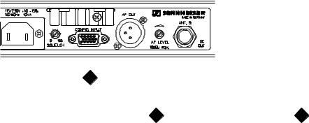
3.2 RÜCKSEITE |
3.2 REAR SIDE |
|
|
|
|
13 |
14 |
15 |
16 |
17 |
18 |
19 |
20 |
13 |
14 |
15 |
16 |
17 |
18 |
19 |
15 |
16 |
17 |
18 |
20 |
13 |
14 |
16 |
17 |
18 |
19 |
21 |
16 |
17 |
18 |
20 |
13 |
Sicherungshalter und Umschalter der Netzspannung |
13 |
Fuse holder and mains voltage selector |
14 |
Netzanschluß (2-poliger Kaltgeräteeinbaustecker) |
14 |
2-pin IEC mains connector |
15 |
Rauschsperreneinsteller, 0 - 100 μV (SQUELCH) |
15 |
Squelch control, 0 - 100 μV (SQUELCH) |
16 |
Service-/Programmierbuchse (CONFIG INPUT) |
16 |
Service interface (CONFIG INPUT) |
17 |
NF-Ausgang, symmetrisch, XLR-3 (AF OUT) |
17 |
AF output, XLR-3, balanced (AF OUT) |
18 |
Lautstärkeeinsteller für NF-Ausgang (AF LEVEL) |
18 |
Control for AF output level (AF LEVEL) |
19 |
Antenneneingang B für Diversity-Betrieb (BNC) |
19 |
Antenna input B for diversity operation (BNC) |
20 |
Antenneneingang A für Diversity-Betrieb (BNC) |
20 |
Antenna input A for diversity operation (BNC) |
21 |
Speisebuchse 11,3 - 18 VDC / 0,8 A |
21 |
DC power supply socket 11.3 - 18 VDC / 0.8 A |
EM 3031, 3032, 3532 07 / 98 - 8
4 TECHNISCHE DATEN
Empfangsfrequenzbereich ................................................................. |
UHF: 430 MHz - 960 MHz |
|
|
VHF: 138 MHz - 260 MHz |
|
Schaltbandbreite ................................................................................ |
UHF: 24 MHz |
|
|
VHF: 7 MHz |
|
Frequenzstabilität ............................................................................... |
UHF: ± 10 ppm (- 10 °C bis + 55 °C) |
|
|
VHF: ± 20 ppm (- 10 °C bis + 55 °C) |
|
Empfangsfrequenzen ......................................................................... |
EM 3031, EM 3032: max. 32 kundenspezifisch programmiert |
|
|
EM 3532: max. 32, im Kanalraster frei wählbar |
|
Kanalabstand (minimal) ...................................................................... |
300 kHz |
|
Kanalraster (minimal) .......................................................................... |
5 kHz |
|
1. Oszillatorfrequenz (1. LO)............................................................... |
UHF: 65,75 MHz unterhalb der Empfangsfrequenz |
|
|
VHF: 10,7 MHz unterhalb der Empfangsfrequenz |
|
1. Zwischenfrequenz (1. ZF) ............................................................... |
UHF: 65,75 MHz |
|
|
VHF: 10,7 MHz |
|
2. Oszillatorfrequenz (2. LO)............................................................... |
UHF: 76,45 MHz (in Sonderfällen 55,05 MHz) |
|
2. Zwischenfrequenz (2. ZF) ............................................................... |
UHF: 10,7 MHz |
|
Deemphasis ....................................................................................... |
50 ms |
|
Modulationsart ................................................................................... |
FM, Breitband |
|
Nennhub............................................................................................. |
± 40 kHz |
|
Spitzenhub ......................................................................................... |
± 56 kHz |
|
NF-Nennausgangspegel ..................................................................... |
+ 12 dBu |
|
NF-Spitzenausgangspegel .................................................................. |
+ 17,5 dBu ± 1 dBu |
|
Monitorpegel ...................................................................................... |
+ 12 dBu, max. Verstärkung = 30 dB |
|
Klirrfaktor bei 1 kHz und Nennhub ..................................................... |
£ 0,5 %, typ. 0,25 % |
|
NF-Frequenzgang (+ 1 dB / - 2 dB) ..................................................... |
45 Hz - 20 kHz |
|
Kompandersystem ............................................................................. |
HiDynplus |
|
Rauschsperre (Squelch) ..................................................................... |
EM 3031, EM 3032: 0 bis 100 mV, einstellbar auf der Rückseite |
|
|
EM 3532: 0 bis 100 mV, einstellbar über Bedienmenue |
|
Empfindlichkeit S/N = 52 dB (Fremd mit HiDynplus) ......................... |
EM 3031: £ 1,0 mV |
|
|
EM 3032, EM 3532: £ 1,5 mV |
|
S/N = 90 dBA (Spitzenhub mit HiDynplus) ......................................... |
£ 5 mV |
|
S/N = 115 dBA (Spitzenhub mit HiDynplus) ....................................... |
£ 15 mV |
|
S/N max. (1 mV, Spitzenhub mit HiDynplus) ...................................... |
120 dBA eff |
|
|
116 dB eff |
|
|
106 dB CCIR peak |
|
Begrenzungseinsatz ........................................................................... |
EM 3031: £ 1,0 mV |
|
|
EM 3032, EM 3532: £ 1,5 mV |
|
Intermodulationsabstand.................................................................... |
³ 66 dB |
|
Nebenempfangsdämpfung ................................................................ |
³ 75 dB |
|
Spiegelfrequenzselektion ................................................................... |
³ 50 dB, typ. 65 dB |
|
HF-Störspannung ............................................................................... |
£ - 57 dBm am HF-Ausgang |
|
Antenneneingänge ............................................................................. |
2 BNC-Buchsen |
|
Antenneneingangsimpedanz .............................................................. |
50 W |
|
NF-Ausgänge...................................................................................... |
LINE: |
3-pol XLR Einbaustecker, trafosymmetrisch |
|
MONITOR: 6,3 mm ø Klinkenbuchse, unsymmetrisch |
|
NF-Ausgangsspannung bei Spitzenhub ............................................. |
LINE: |
0 bis 5,6 V einstellbar, ³ 2 kW |
|
MONITOR: |
0 bis 2,8 V einstellbar, ³ 600 W |
Quellimpedanz der NF-Ausgänge ...................................................... |
£ 50 W (LINE bei max. Pegel) |
|
Temperaturbereich ............................................................................. |
- 10 °C bis + 55 °C |
|
Stromversorgung ............................................................................... |
115 / 230 V AC + 10 % / - 15 % |
|
Leistungsaufnahme............................................................................ |
EM 3031: 10 VA |
|
|
EM 3032, EM 3532: 15 VA |
|
Abmessungen (ohne Montagewinkel) ............................................... |
436 x 228 x 43 mm (19", 1 HE) |
|
Gewicht .............................................................................................. |
EM 3031: ca. 3300 g |
|
|
EM 3032, EM 3532: ca. 4000 g |
|
BTZ-Nummer...................................................................................... |
EM 3031-U: A 128 308H RF |
|
|
EM 3032-U: A 128 310H RF |
|
Konformitätsnorm .............................................................................. |
EM 3532-U: ETS 300 445 |
|
|
EM 3031-V: ETS 300 422 |
|
|
EM 3032-V: ETS 300 445 |
|
EM 3031, 3032, 3532 07 / 98 - 9
4 TECHNICAL DATA
Frequency range ................................................................................ |
UHF: 430 MHz - 960 MHz |
|
|
VHF: 138 MHz - 260 MHz |
|
Switching bandwidth.......................................................................... |
UHF: 24 MHz |
|
|
VHF: 7 MHz |
|
Frequency stability ............................................................................. |
UHF: ± 10 ppm (- 10 °C to + 55 °C) |
|
|
VHF: ± 20 ppm (- 10 °C to + 55 °C) |
|
Receiver frequencies ......................................................................... |
EM 3031, EM 3032: max. 32, pre-programmed |
|
|
EM 3532: max. 32 programmable in channel grid |
|
Channel spacing (min.) ....................................................................... |
300 kHz |
|
Channel grid (min.) ............................................................................. |
5 kHz |
|
1st oscillator frequency (1. LO) .......................................................... |
UHF: 65.75 MHz below receiver frequency |
|
|
VHF: 10.7 MHz below receiver frequency |
|
1st intermediate frequency (1. IF) ...................................................... |
UHF: 65.75 MHz |
|
|
VHF: 10.7 MHz |
|
2nd oscillator frequency (2. LO) ......................................................... |
UHF: 76.45 MHz (optional 55.05 MHz) |
|
2nd intermediate frequency (2. IF) ..................................................... |
UHF: 10.7 MHz |
|
De-emphasis ...................................................................................... |
50 ms |
|
Modulation ......................................................................................... |
wideband FM |
|
Nominal deviation............................................................................... |
± 40 kHz |
|
Peak deviation .................................................................................... |
± 56 kHz |
|
Nominal AF output level ..................................................................... |
+ 12 dBu |
|
Peak AF output level .......................................................................... |
+ 17.5 dBu ± 1 dBu |
|
Monitor level ...................................................................................... |
+ 12 dBu, max. amplification = 30 dB |
|
THD at 1 kHz and nominal deviation .................................................. |
£ 0.5 %, typ. 0.25 % |
|
AF frequency response (+ 1 dB/- 2 dB) .............................................. |
45 Hz - 20 kHz |
|
Compander system ............................................................................ |
HiDynplus |
|
Squelch .............................................................................................. |
EM 3031, EM 3032: 0 - 100 mV, adjustable (rear side) |
|
|
EM 3532: 0 - 100 mV, programmable (menue) |
|
Sensitivity S/N = 52 dB (unweighted with HiDynplus) ....................... |
EM 3031: £ 1.0 mV |
|
|
EM 3032, EM 3532: £ 1.5 mV |
|
S/N = 90 dBA (peak deviation with HiDynplus) .................................. |
£ 5 mV |
|
S/N = 115 dBA (peak deviation with HiDynplus) ................................ |
£ 15 mV |
|
S/N max. (1 mV, peak deviation with HiDynplus) ............................... |
120 dBA eff |
|
|
116 dB eff |
|
|
106 dB CCIR peak |
|
Limiter threshold ................................................................................ |
EM 3031: £ 1.0 mV |
|
|
EM 3032, EM 3532: £ 1.5 mV |
|
Intermodulation attenuation ............................................................... |
³ 66 dB |
|
Adjacent channel rejection ................................................................. |
³ 75 dB |
|
Image rejection .................................................................................. |
³ 50 dB, typ. 65 dB |
|
Free field interference radiation ......................................................... |
£ - 57 dBm at the AF output |
|
Antenna inputs ................................................................................... |
2 BNC sockets |
|
Antenna input impedance .................................................................. |
50 W |
|
AF outputs.......................................................................................... |
LINE: |
3-pin XLR, transformer-balanced |
|
MONITOR: 1/4" (6.3 mm) ø jack plug, unbalanced |
|
AF output voltage at peak deviation ................................................... |
LINE: |
0 - 5.6 V, adjustable, ³ 2 kW |
|
MONITOR: |
0 - 2.8 V, adjustable, ³ 600 W |
Source impedance of AF output ........................................................ |
£ 50 W (LINE at max. level) |
|
Temperature range............................................................................. |
- 10 °C to + 55 °C |
|
Power supply ..................................................................................... |
115 / 230 V AC + 10 % / - 15 % |
|
Power consumption ........................................................................... |
EM 3031: 10 VA |
|
|
EM 3032, EM 3532: 15 VA |
|
Dimensions (without rack mount ears) .............................................. |
436 x 228 x 43 mm (19", 1 U) |
|
Weight................................................................................................ |
EM 3031: approx. 3300 g |
|
|
EM 3032, EM 3532: approx. 4000 g |
|
EM 3031, 3032, 3532 07 / 98 - 10
5 MESSGERÄTE UND PRÜFMITTEL |
5 MEASURING AND TEST EQUIPMENT |
||
1 |
Spektrum-Analysator (z.B. Advantest R 4131 A) |
1 |
Spectrum analyser (e.g. Advantest R 4131 A) |
1 |
Tracking-Generator (z.B. Advantest TR 4131 A) |
1 |
Tracking generator (e.g. Advantest TR 4131 A) |
1 |
HF-Signalgenerator (z.B. Rohde & Schwarz SMS 2) |
1 |
RF signal generator (e.g. Rohde & Schwarz SMS 2) |
1 |
Frequenzmeßgerät (z.B. HEB Digicount) |
1 |
Frequency meter (e.g. HEB Digicount) |
1 |
NF-Multimeter (z.B. Sennheiser UPM 550-1) |
1 |
AF multimeter (e.g. Sennheiser UPM 550-1) |
1 |
Oszilloskop (z.B. Hameg 605) |
1 |
Oscilloscope (e.g. Hameg 605) |
1 |
Voltmeter Ri ³ 1 MW / V (z.B. Thandar TM 351) |
1 |
Voltmeter Ri ³ 1 MW / V (e.g. Thandar TM 351) |
1 |
Amperemeter (z.B. Thandar TM 351) |
1 |
Ammeter (e.g. Thandar TM 351) |
1 |
IBM-kompatibler PC (mit Windows ab V3.1) |
1 |
IBM compatible PC (with Windows, version 3.1 or later) |
5.1 SPEZIELLE SERVICE-HILFSMITTEL |
5.1 SPECIAL SERVICE TOOLS |
||
- Service-Adapter M-SePT2 PH (Bestell-Nr. 70507) |
- M-SePT2 PH service adaptor (spare part no. 70507) |
||
- Programmier-Software SePT.EXE V3.0 (Bestell-Nr. 70502) |
- SePT.EXE V3.0 programming tool (spare part no. 70502) |
||
- DC-Trennadapter M10 (Bestell-Nr. 40838) |
- M10 DC voltage isolating adaptor (spare part no. 40838) |
||
SePT.EXE
Version 3.0
Programmier-Software SePT.EXE V3.0 (Bestell-Nr. 70502) SePT.EXE V3.0 programming tool (spare part no. 70502)
Service-Adapter M-SePT2 PH (Bestell-Nr. 70507) M-SePT2 PH service adaptor (spare part no. 70507)
DC-Trennadapter M10 (Bestell-Nr. 40838)
M10 DC voltage isolating adaptor (spare part no. 40838)
5.2 SERVICE-SET SePT2
Die neuen Service-Hilfsmittel sind auch komplett als ServiceSet SePT2 (Bestell-Nr. 70532) erhältlich. Das Set besteht aus:
-1 x Service-Adapter M-SePT2 PH
-1 x Programmier-Software SePT.EXE V3.0
-1 x Software-Registrationskarte
-1 x Installationshinweise
5.2 SePT2 SERVICE SET
All new service tools are available as a complete set (spare part no. 70532). This set contains:
-1 x M-SePT2 PH service adaptor
-1 x SePT.EXE V3.0 programming tool
-1 x software registration card
-1 x installation instructions
EM 3031, 3032, 3532 07 / 98 - 11

6 SYSTEMÜBERSICHT
6.1 ÜBERSICHT DER MODIFIKATIONEN
Die folgende Tabelle zeigt eine Übersicht der Empfänger der 3000er Serie sowie die Möglichkeiten der Nachrüstung. Detailierte Anweisungen zu den Modifikationen sind dem Kapitel "Modifikationen" zu entnehmen.
6 SYSTEM OVERVIEW
6.1 MODIFICATION OVERVIEW
The following table shows an overview of the 3000 receiver series and possible modifications. Detailed instructions to this modifications you will find in the chapter "modifications".
Gerätebezeichnung |
Artikelnummer |
Frequenzbereich |
Schaltbandbreite |
Empfänger1 |
Empfänger2 |
DC-Speisung |
S-MCD |
|||
Product name |
|
Catalog no. |
|
Frequency range |
Switching bandwidth |
Receiver1 |
Receiver2 |
DC powering |
S-MCD |
|
|
|
|
|
|
|
|
|
|
|
|
EM 3031-U |
|
04555 |
|
434 - 960 MHz |
24 MHz |
X |
– |
|
O |
– |
EM 3032-U |
|
04556 |
|
434 - 960 MHz |
24 MHz |
X |
X |
|
O |
O |
EM 3532-U |
|
04400 |
|
434 - 960 MHz |
24 MHz |
X |
X |
|
X |
X |
EM 3031-V |
|
04365 |
|
138 - 260 MHz |
7 MHz |
X |
– |
|
O |
– |
EM 3032-V |
|
04201 |
|
138 - 260 MHz |
7 MHz |
X |
X |
|
O |
– |
|
|
|
|
|
|
|
|
|
|
|
X bestückt |
– nicht bestückt |
O nachrüstbar |
X equipped |
– not equipped |
O optionally |
|||||
|
|
|
|
|
|
|
|
|
|
|
6.2 ÜBERSICHT DER MODULVERWENDUNG
Die folgende Tabelle zeigt eine Übersicht der Module in den Empfängern der 3000er Serie. Detailierte Informationen zu den Modulen sind den entsprechenden Kapiteln der Service-Anlei- tung zu entnehmen.
6.2 ASSEMBLY OVERVIEW
The following table shows an overview of the 3000 receiver series and the used assemblies. Detailed informations to the modifications you will find in the chapter "modifications".
Gerätebezeichnung |
Tuner-Modul |
ZF-Modul |
Schalt-Modul |
HDP-Modul |
Prozessor-Modul |
Anzeige-Modul |
DC/DC-Modul |
Product name |
Tuner Assembly |
IF Assembly |
Diversity Assembly |
HDP Assembly |
Processor Assembly |
Display Assembly |
DC/DC Assembly |
|
ASSY2 |
ASSY1, ASSY2 |
ASSY3 |
ASSY4 |
ASSY5 |
ASSY6 |
ASSY1 |
|
|
|
|
|
|
|
|
EM 3031-U |
1 x A001 |
2 x A002 |
1 x A003 |
1 x A004 |
1 x A015 |
1 x A006 |
1 x A007 |
EM 3032-U |
2 x A001 |
4 x A002 |
2 x A003 |
2 x A004 |
2 x A015 |
2 x A006 |
2 x A007 |
EM 3532-U |
2 x A001 |
4 x A002 |
2 x A003 |
2 x A004 |
2 x A014 |
2 x A006 |
2 x A007 |
EM 3031-V |
1 x A012 |
2 x A002 |
1 x A003 |
1 x A004 |
1 x A015 |
1 x A006 |
1 x A007 |
EM 3032-V |
2 x A012 |
4 x A002 |
2 x A003 |
2 x A004 |
2 x A015 |
2 x A006 |
2 x A007 |
|
|
|
|
|
|
|
|
NOTIZEN: NOTES:
EM 3031, 3032, 3532 07 / 98 - 12
7 SERVICE HINWEISE
7.1 ALLGEMEINES ÜBERPRÜFEN
Zur Eingrenzung von Fehlern empfiehlt es sich den Empfänger mit einem funktionsfähigen Sender (z.B. SKM 3072/SKM 5000) zu überprüfen. Hierzu wird der Handsender wie in der Praxis betrieben. Der Empfänger wird betriebsbereit gemacht (Netzstecker einstecken, Empfänger einschalten, Kanalwahlschalter aufSendefrequenzeinstellen,Antennenanschließen,Verstärker am Ausgang anschließen (oder Kopfhörer in Kopfhörerausgang kontaktieren) und Signal abhören). Im Praxistest wird der Empfänger nun auf folgende Merkmale überprüft:
1.Klang (Modulation, Verzerrungen)
2.Rauschen (Empfindlichkeit, Reichweite min. 50 m)
3.Diversityverhalten (Sender im Abstand von ca. 1 Meter zwischen den Antenneneingängen, evtl. Betrieb des Empfängers ohne Antennen, hin und her bewegen)
4.Funktion der Bedienelemente (Volume, Squelch, Channel)
5.Wackelkontakte (Abklopfen)
7.2 EMPFANGSEIGENSCHAFTEN ÜBERPRÜFEN
Bei Empfängern die vermutlich eine unzureichende Empfindlichkeit haben (mangelnde Reichweite) ist dieses mit Hilfe eines HF-Signalgenerators zu überprüfen. Hierzu ist der HFSignalgenerator (HF-Trägerfrequenz auf mittleren Kanal innerhalb der Schaltbandbreite, HF-Ausgangsspannung 100 μV, Frequenzhub 40 kHz, Modulation 1 kHz) über DC-Trennadapter an den Antenneneingang ANT. A anzuschließen. Der Empfänger wird nun betriebsbereit gemacht (Netzstecker einstecken, Empfänger einschalten, Kanalwahlschalter einstellen, NFMultimeter und Oszilloskop an Ausgang J3 anschließen und Signal am NF-Multimeter abhören). Nun die Messungen Nr. 9 bis 10 der Prüfund Abgleichanweisung durchführen. Anschließend die Funktion der Rauschsperre und der Anzeigen überprüfen.
7 SERVICE INSTRUCTIONS
7.1 GENERAL TEST
To narrow down the possible causes of faults, it is advisable to test the receiver with an operational transmitter (e.g. SKM 3072/SKM 5000). Put the receiver into operation (connect the plug-in mains unit, switch the receiver on, set the channel selector switch to the transmitter frequency, connect antennas connect a monitoring amplifier to the receiver output - or connect a headphone to the headphone output - and listen to the signal). In a practical test, the receiver is now checked for the following:
1.Sound quality (modulation, distortion)
2.Noise (sensitivity, range min. 50 m)
3.Diversity operation (transmitter at a distance of approx. 1 m between the antenna inputs; perhaps operate the receiver without antennæ and move it back and forth)
4.Functioning of operating elements (volume control, squelch, channel selector switch)
5.Loose contacts (by knocking at the housing)
7.2 RECEPTION TEST
If the sensitivity of the receiver is probably too low (range is reduced), test the sensitivity with an RF signal generator. Connect the RF signal generator (set the RF carrier frequency to a channel in the center of the switching bandwidth, RF output voltage 100 μV, deviation 40 kHz, modulation 1 kHz) via a DC voltage isolating adaptor to antenna input ANT.A. Put the receiver into operation (connect the plug-in mains unit, switch the receiver on, set the channel selector switch, connect the AF multimeter and the oscilloscope to the J3 output and listen to the signal at the AF multimeter). Now carry out measurements 9 and 10 of the test and alignment instructions. Then check the functioning of the squelch and the displays.
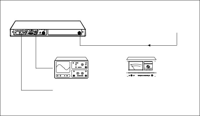
MESSAUFBAU |
TEST SET-UP |
HF - Signalgenerator / RF signal generator
Empfänger / Receiver
RF
Oszilloskop / Oscilloscope |
NF - Multimeter / AF meter |
||||||||||
|
|
|
|
|
|
|
|
|
|
|
|
|
|
|
|
|
|
|
|
|
|
|
|
|
|
|
|
|
|
|
|
|
|
|
|
|
|
|
|
|
|
|
|
|
|
|
|
|
|
|
|
|
|
|
|
|
|
|
|
|
|
|
|
|
|
|
|
|
|
|
|
Netzstecker, Spannung laut Spannungswähler (Sicherung)
Mains plug, mains voltage according to voltage selector (fuse)
HF-Signalgenerator auf Empfangsfrequenz, HF-Ausgangsspannung 100 μV, Frequenzhub 40 kHz,
Modulation 1kHz
RF signal generator to receiver frequency, RF output voltage 100 μV,
Deviation 40 kHz, Modulation 1kHz
EM 3031, 3032, 3532 07 / 98 - 13

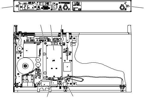
7.3 ABGLEICH UND FEHLERSUCHE
Zum Abgleich und zur Reparatur ist das Gehäuse der Empfänger zu demontieren.
1.Gehäuse öffnen; dazu mit Schraubendreher zwei Schrauben (1) auf der Rückseite des Chassis lösen und entfernen. Chassis nach vorne aus dem Gehäuse ziehen.
2.Schrauben (2) des Abschirmdeckels lösen und entfernen.
1
7.3 ALIGNMENT AND TROUBLESHOOTING
For alignment or repairs the receivers have to be disassembled.
1.For opening the housing, unlock two screws (1) on the rear of the chassis with a screwdriver. Pull the chassis forwards out of the housing.
2.Remove the screws (2) from the lid of the RF screen.
1
2
3.Abschirmdeckel von Abschirmprofil entnehmen.
4.Beim Abgleich ist auf die Position der Widerstandstrimmer zu achten.
3.Remove the lid.
4.During alignment, pay attention to the position of the trimming resistors:
Max. Links |
Mittelstellung |
Max. Rechts |
toter Bereich |
left max. |
centre position |
right max. |
dead band |
Achtung! Die Widerstandstrimmer haben keinen Anschlag. Beim Abgleich ist darauf zu achten, daß Einstellungen nicht am Rande oder im "toten Bereich" vorgenommen werden.
5.Empfänger betriebsbereit machen; dazu Netzstecker an Stromversorgungsbuchse anschließen. Empfänger über Trenntransformator versorgen.
6.Empfänger mit Betriebsschalter S1 einschalten.
7.Mit Schalter "SET" und "UP", bzw. "DOWN" auf Kanal in der Mitte der Schaltbandbreite schalten.
8.HF-Signalgenerator wie in der Prüf - und Abgleichanweisung beschrieben an Antenneneingang ANT. A anschließen. Dazu DC-Trennadapter M10 (Bestell.-Nr. 40838) verwenden, da am Antenneneingang die Boosterspeisung liegt.
Grundeinstellungen des HF-Signalgenerators:
HF-Trägerfrequenz: wie 7., HF-Ausgangsspannung: 100 μV, Frequenzhub: 40 kHz, Modulation: 1 kHz
9.NF-Ausgang J3 mit NF-Multimeter und Oszilloskop verbinden (XLR-Buchse J3, Pin2 nach Pin3, Pin1 - Masse).
10.Prüfund Abgleichanweisung durchführen. Bei stark abweichenden Meßwerten können die Leiterplatten unter Zuhilfenahme des Stromlaufplans repariert werden oder komplette Module getauscht werden.
Attention! The trimming resistors do not have an end stop. When aligning, make sure that they are not set near or in the dead band.
5.To put the receiver into operation, connect the plug-in mains to the mains. Power the receiver via an isolating transformer.
6.Switch the receiver on with operating switch S1.
7.With the buttons "SET" and "UP" or "DOWN", select the channel at the middle of the receiver's switching bandwidth.
8.Connect the RF signal generator to the antenna input ANT.A as described in the test and alignment instructions. Use the M10 DC voltage isolating adaptor (spare part no. 40838), as the booster supply is applied to the antenna input.
Basic settings of the RF signal generator:
RF carrier frequency: as in 7, RF output voltage: 100 μV, Deviation: 40 kHz, Modulation: 1 kHz
9.Connect the AF output J3 to the AF multimeter and the oscilloscope (XLR socket J3, pin2 to pin3, pin1 - GND).
10.Carry out test and alignment instructions. If the measured values deviate strongly from the required values, the PCBs can be repaired using the circuit diagram or complete assemblies can be replaced.
EM 3031, 3032, 3532 07 / 98 - 14
7.4 FEHLERMELDUNGEN EM 3031 UND EM 3032
Bei Störungen und internen Fehlfunktionen detektiert der Mikroprozessor der Empfänger EM 3031 und EM 3032 dieses und zeigt eine Fehlermeldung auf dem Anzeige-Modul an.
ERR 1: Der Prozessor (Prozessor-Modul / U3) hat keinen Kontakt zum EEPROM (Tuner-Modul / U203).
Mögliche Ursachen:
-Leitungen zwischen Prozessor-Modul und Tuner-Modul unterbrochen oder kurzgeschlossen.
-Spannungsversorgung des Tuner-Moduls ausgefallen.
-EEPROM U203 auf dem Tuner-Modul defekt.
-PLL-Kreis defekt.
ERR 2: EEPROM U203 im Tuner-Modul leer.
Mögliche Ursachen:
-EEPROM falsch programmiert (z.B. Abbruch während des Programmiervorgangs).
ERR 3: Falsches Tuner-Modul im Empfänger. Geräte arbeiten nur mit EM 3031-U, 3032-U, EM 3031-V, 3032-V oder SPARE30-U, SPARE30-V konfigurierten Tuner-Modulen.
Mögliche Ursachen:
-Das falsche Tuner-Modul ist bestückt worden.
ERR 4: PLL hat nicht gerastet.
Mögliche Ursachen:
-+ 8 VDC Betriebsspannung am Tuner-Modul fehlt.
-+ 5 VDC an der PLL fehlen.
-PLL defekt.
-Oszillatorspannung (VCO) nicht im Regelbereich.
-Nach Programmierung der Schaltbandbreite mit der Software SePT.EXE erfolgte kein Abgleich des Tuner-Moduls.
-Nach Programmierung der Kanalfrequenzen mit der Software SePT.EXE sind Kanalfrequenzen außerhalb der Schaltbandbreite des Tuner-Moduls programmiert worden.
7.5 FEHLERMELDUNGEN EM 3532-U
Ein Ausrasten der PLL detektiert der Mikroprozessor des Empfängers EM 3532-U und zeigt dieses durch Blinken der Frequenz-/Kanalanzeige auf dem Anzeige-Modul an.
7.6 TIPS ZUR FEHLERSUCHE
Mit der Prüfund Abgleichanweisung läßt sich eine Überprüfung und eine Signalververfolgung des Empfängers durchführen. Anhand der ermittelten Werte lassen sich Aussagen über defekte Schaltungsteile und defekte Module treffen.
Die defekten Bauteile, bzw. Module können im Servicefall durch entsprechende Ersatzteile ersetzt werden.
Bei vermuteten Fehlern im Bereich des Prozessor-Moduls und des Anzeige-Moduls ist ebenfalls nach der Prüfund Abgleichanweisung (Nr. 6 - 6.4 und Nr. 8 - 8.2) zu verfahren. Läßt sich danach keine eindeutige Fehlerdiagnose stellen, ist bei ausgeschaltetem Empfänger der Flexverbinder des Anzeige-Moduls von der Hauptplatine (P6) zu lösen. Anschließend ist das Anzeige-Modul durch ein funktionsfähiges Ersatz-Anzeige- Modul auszutauschen (lediglich Flexverbinder in P6 stecken). Ist der Fehler des Empfängers nun beseitigt, ist das Ersatz- Anzeige-Modul ordnungsgemäß zu montieren. Tritt der gleiche Fehler erneut auf, ist das Prozessor-Modul auszutauschen und der Empfänger erneut auf den Fehler zu überprüfen.
7.4 EM 3031 AND EM 3032 ERROR MESSAGES
Errors or internal malfunctions are detected by the receiver's microprocessor and an error message is displayed on the display assembly.
ERR 1: The processor (processor assembly / U3) has no contact to the EEPROM (tuner assembly / U203).
Possible causes:
-Connections between the processor assembly and the tuner assembly are interrupted or short circuited.
-Voltage supply to the tuner assembly has failed.
-EEPROM U203 on the tuner assembly is defective.
-PLL is defective.
ERR 2: EEPROM U203 in the tuner assembly is empty.
Possible causes:
-EEPROM has been wrongly programmed (e.g. cancellation during the programming process).
ERR 3: Wrong tuner assembly in the receiver. Receivers only work with tuner assemblies configured for EM 3031-U, 3032-U, EM 3031-V, 3032-V or SPARE30-U, SPARE30-V.
Possible causes:
-Replacement tuner assembly has been confused.
ERR 4: PLL has not locked.
Possible causes:
-+ 8 VDC operating voltage at tuner assembly is not present.
-+ 5 VDC at PLL is not present.
-PLL is defective.
-Oscillator voltage (VCO) is outside the tuning voltage.
-After programming the switching bandwidth with the SePT.EXE software, the tuner assembly has not been aligned.
-After programming the channel frequencies with the SePT.EXE software, channel frequencies have been programmed outside the switching bandwidth of the tuner assembly.
7.5 EM 3532-U ERROR MESSAGES
When the PLL unlock error is detected by the microprocessor of the EM 3532 receiver, the display indicates this by blinking.
7.6 HINTS FOR TROUBLESHOOTING
With the test and alignment instructions, it is possible to test the receiver and to trace the signal. On the basis of the values observed, conclusions can be drawn about defective circuit sections and defective assemblies.
Defective components or assemblies can be replaced by the proper replacement parts.
If defects are suspected in the area of the processor assembly and the display assembly, the test and alignment instructions (No. 6 - 6.4 and No. 8 - 8.2) should also be carried out. If this does not permit a clear error diagnosis, switch the receiver off and detach the flexible connection of the display assembly from the main PCB (P6). Then replace the display assembly by a functional replacementdisplayassembly(simplyplugtheflexibleconnector into P6). If the error in the receiver is then eliminated, the display assembly has to be replaced. If the same error occurs again, replace the processor assembly and then retest the receiver for the same error.
EM 3031, 3032, 3532 07 / 98 - 15

8 MODIFIKATIONEN
8.1FREQUENZEN INNERHALB DER SCHALTBANDBREITE
Achtung: Während das Programmierkabel M-SePT2 PH auf der Empfängerschnittstelle "CONFIG INPUT" gesteckt ist, nicht die Bedienelemente "SET", "UP" und "DOWN" benutzen!
1.Empfänger betriebsbereit machen; dazu Netzstecker an Stromversorgungsbuchse anschließen. Empfänger an Netzspannung anschließen.
2.Empfänger mit Betriebsschalter S1 einschalten.
3.Service-Adapter M-SePT2 PH (Bestell-Nr. 70507) mit freien COM-Port des IBM-kompatiblen PC's verbinden.
4.Service-Adapter M-SePT2 PH auf Programmierbuchse J5 (CONFIG INPUT) der Empfänger-Rückseite stecken.
8 MODIFICATIONS
8.1FREQUENCIES WITHIN THE SWITCHING BANDWIDTH
Attention: Do not use the switches "SET", "UP", and "DOWN" on the front panel while the programming cable M-SePT2 PH is connected to the receiver bus "CONFIG INPUT"!
1.Put the receiver into operation (connect the mains cable to the mains power supply,connect the receiver to the mains voltage.
2.Switch the receiver on with switch S1.
3.Connect the M-SePT2 PH service adaptor (spare part no. 70507) to the unused COM port of the IBM compatible PC.
4.Connect the M-SePT2 PH service adaptor to the J5 programming socket (CONFIG INPUT) on the rear of the receiver.
Empfänger
Receiver
|
|
|
|
|
|
|
|
|
|
|
|
|
|
|
|
|
|
|
|
|
|
|
|
|
|
|
|
|
|
|
|
|
|
|
|
|
|
|
|
|
|
|
|
|
|
|
|
M-SePT2 PH |
|
|
|
|
IBM compatible |
|
|
|
|
SePT.EXE V3.0 |
|||||
|
|
|
|
|
|
|
|
||||||||
|
|
|
|
PC |
|
|
|
|
|
||||||
Service adaptor |
|
|
|
|
³ V3.1 |
|
|
|
|
programming tool |
|||||
|
|
|
|
|
|
|
|
||||||||
|
|
|
|
Windows |
|
|
|
|
|||||||
|
|
|
|
|
|
|
|
|
|
|
|
|
|
||
|
|
|
|
|
|
|
|
|
|
|
|
|
|
|
|
5.Programm SePT.EXE (ab V3.0) unter Windows starten.
6.Die Daten des EEPROM's werden ausgelesen und im Programmfenster angezeigt.
7.Die neuen Kanalfrequenzen können nun eingegeben werden. Das Programm SePT.EXE unterstützt die Online-Hilfe. Mit der "Help"-Funktion können somit Informationen über die Bedienung der Programm-Software abgerufen werden.
8.Nach dem Programmiervorgang fragt das Programm SePT.EXE automatisch den Inhalt des EEPROM's ab.
9.Nach dem Überprüfen des gespeicherten Inhaltes kann der Service-Adapter M-SePT2 PH von der Programmierbuchse J5 entfernt werden.
10.Da sich die programmierten Frequenzen innerhalb der bisherigen Schaltbandbreite befinden, sind lediglich die Empfangsfrequenzen und Spezifikationen des Empfängers zu überprüfen.
8.2FREQUENZEN AUSSERHALB DER SCHALTBANDBREITE
Achtung: Während das Programmierkabel M-SePT2 PH auf der Empfängerschnittstelle "CONFIG INPUT" gesteckt ist, nicht die Bedienelemente "SET", "UP" und "DOWN" benutzen!
1.Empfänger betriebsbereit machen; dazu Netzstecker an Stromversorgungsbuchse anschließen. Empfänger an Netzspannung anschließen.
2.Empfänger mit Betriebsschalter S1 einschalten.
3.Service-Adapter M-SePT2 PH (Bestell-Nr. 70507) mit freien COM-Port des IBM-kompatiblen PC's verbinden.
4.Service-Adapter M-SePT2 PH auf Programmierbuchse J5 (CONFIG INPUT) der Empfänger-Rückseite stecken.
5.Start the SePT.EXE programming tool (V3.0 or later) under Windows.
6.SePT.EXE reads in and displays the receiver's EEPROM data.
7.You can now enter new channel frequencies. SePT.EXE has online help. For information on how to use the software simply choose the "Help" command.
8.After programming, SePT.EXE automatically displays the EEPROM data.
9.After you have checked the stored data, remove the M- SePT2 PH service adaptor from the J5 programming socket.
10.As the programmed frequencies are within the previous switching bandwidth, you only have to check receiving frequencies and receiver data.
8.2FREQUENCIES OUTSIDE THE SWITCHING BANDWIDTH
Attention: Do not use the switches "SET", "UP", and "DOWN" on the front panel while the programming cable M-SePT2 PH is connected to the receiver bus "CONFIG INPUT"!
1.Put the receiver into operation (connect the mains cable to the mains power supply,connect the receiver to the mains voltage.
2.Switch the receiver on with switch S1.
3.Connect the M-SePT2 PH service adaptor (spare part no. 70507) to the unused COM port of the IBM compatible PC.
4.Connect the M-SePT2 PH service adaptor to the J5 programming socket (CONFIG INPUT) on the rear of the receiver.
EM 3031, 3032, 3532 07 / 98 - 16
Empfänger
Receiver
|
|
|
|
|
|
|
|
|
|
|
|
|
|
|
|
|
|
|
|
|
|
|
|
|
|
|
|
|
|
|
|
|
|
|
|
|
|
|
|
|
|
|
|
|
|
|
|
M-SePT2 PH |
|
|
|
|
IBM compatible |
|
|
|
|
SePT.EXE V3.0 |
|||||
|
|
|
|
|
|
|
|
||||||||
|
|
|
|
PC |
|
|
|
|
|
||||||
Service adaptor |
|
|
|
|
³ V3.1 |
|
|
|
|
programming tool |
|||||
|
|
|
|
|
|
|
|
||||||||
|
|
|
|
Windows |
|
|
|
|
|||||||
|
|
|
|
|
|
|
|
|
|
|
|
|
|
||
|
|
|
|
|
|
|
|
|
|
|
|
|
|
|
|
5.Programm SePT.EXE (ab V3.0) unter Windows starten.
6.Die Daten des EEPROM's werden ausgelesen und im Programmfenster angezeigt.
7.Die neuen Kanalfrequenzen können nun eingegeben werden. Das Programm SePT.EXE unterstützt die Online-Hilfe. Mit der "Help"-Funktion können somit Informationen über die Bedienung der Programm-Software abgerufen werden.
8a. UHF-Empfänger: Die Grenzen der Schaltbandbreite (24 MHz) können durch Halten der Tasten ALT, CTRL und gleichzeitigen Maus-Klick auf den Button "Chk Data" verändert werden. Die Grenzen der eingegebenen, neuen Schaltbandbreite müssen sich unbedingt innerhalb der Grenzen des bestückten HF-Teils (RF-Amplifier, VCO, Buffer) befinden. Ebenso ist die neue Schaltbandbreite auf 24 MHz zu berechnen. Der bestückte Bereich des Tuner-Moduls ist zu erkennen an den Kodierwiderständen R501 - R505.
Bereich Nr. 1: |
430 - 494 MHz |
R501 bestückt |
Bereich Nr. 2: |
470 - 598 MHz |
R502 bestückt |
Bereich Nr. 3: |
574 - 702 MHz |
R503 bestückt |
Bereich Nr. 4: |
680 - 814 MHz |
R504 bestückt |
Bereich Nr. 5: |
798 - 960 MHz |
R505 bestückt |
5.Start the SePT.EXE programming tool (V3.0 or later) under Windows.
6.SePT.EXE reads in and displays the receiver's EEPROM data.
7.You can now enter new channel frequencies. SePT.EXE has online help. For information on how to use the software simply choose the "Help" command.
8a. UHF receiver: The limits of the switching bandwidth (24 MHz) can be changed by holding down the ALT and CTRL keys and simultaneously clicking the "Chk Data" button. It is essential that the limits of the new switching bandwidth entered are within the limits determined by the components of the RF section (RF amplifier, VCO, buffer). Also, the new switching bandwidth has to be calculated to 24 MHz. The component side of the tuner assembly can be identified by the coded resistors R501 - R505.
Range No. 1: |
430 - 494 MHz |
R501 mounted |
Range No. 2: |
470 - 598 MHz |
R502 mounted |
Range No. 3: |
574 - 702 MHz |
R503 mounted |
Range No. 4: |
680 - 814 MHz |
R504 mounted |
Range No. 5: |
798 - 960 MHz |
R505 mounted |
8b. VHF-Empfänger: Die Grenzen der Schaltbandbreite (7 MHz) können durch Halten der Tasten ALT, CTRL und gleichzeitigen Maus-Klick auf den Button "Chk Data" verändert werden. Die Grenzen der eingegebenen, neuen Schaltbandbreite müssen sich unbedingt innerhalb der Grenzen des bestückten HF-Teils (RF-Amplifier, VCO, Buffer) befinden. Ebenso ist die neue Schaltbandbreite auf 7 MHz zu berechnen. Der bestückte Bereich des Tuner-Moduls ist zu erkennen an den Kodierwiderständen R501 - R504.
Bereich Nr. 1: |
138 - 155 MHz |
R501 bestückt |
Bereich Nr. 2: |
148 - 181 MHz |
R502 bestückt |
Bereich Nr. 3: |
174 - 233 MHz |
R503 bestückt |
Bereich Nr. 4: |
216 - 260 MHz |
R504 bestückt |
8b. VHF receiver: The limits of the switching bandwidth (7 MHz) can be changed by holding down the ALT and CTRL keys and simultaneously clicking the "Chk Data" button. It is essential that the limits of the new switching bandwidth entered are within the limits determined by the components of the RF section (RF amplifier, VCO, buffer). Also, the new switching bandwidth has to be calculated to 7 MHz. The component side of the tuner assembly can be identified by the coded resistors R501 - R505.
Range No. 1: |
138 - 155 MHz |
R501 mounted |
Range No. 2: |
148 - 181 MHz |
R502 mounted |
Range No. 3: |
174 - 233 MHz |
R503 mounted |
Range No. 4: |
216 - 260 MHz |
R504 mounted |
9.Nach dem Programmiervorgang fragt das Programm SePT.EXE automatisch den Inhalt des EEPROM's ab.
10.Nach dem Überprüfen des gespeicherten Inhaltes kann der Service-Adapter M-SePT2 PH von der Programmierbuchse J5 entfernt werden.
11.Da sich die programmierten Frequenzen außerhalb der alten Schaltbandbreite, aber innerhalb der Grenzen des bestückten HF-Teils (RF-Amplifier, VCO, Buffer) befinden, ist ein Neuabgleich laut Prüfund Abgleichanweisung (siehe auch Kapitel 5.3) erforderlich. Vor dem Neuabgleich erscheint auf dem Anzeige-Modul üblicherweise eine Fehlermeldung "ERR 4", da die Bereichsgrenzen der Tuningspannung (Prüfund Abgleichanweisung Nr. 2.1) noch nicht abgeglichen wurden.
9.After programming, SePT.EXE automatically displays the EEPROM data.
10.After you have checked the stored data, remove the M- SePT2 PH service adaptor from the J5 programming socket.
11.As the programmed frequencies are outside the previous switching bandwidth but within the limits determined by the components of the RF section (RF amplifier, VCO, buffer), the receiver has to be re-aligned according to the test and alignment instructions (see also chapter 5.3). Before re-alignment, an error message "ERR 4" normally appears on the display assembly because the limits of the tuning voltage (test and alignment instruction No. 2.1) have not yet been adjusted.
EM 3031, 3032, 3532 07 / 98 - 17
8.3 EM 3031/32 TUNER-MODUL AUSTAUSCHEN
Achtung: Während das Programmierkabel M-SePT2 PH auf der Empfängerschnittstelle "CONFIG INPUT" gesteckt ist, nicht die Bedienelemente "SET", "UP" und "DOWN" benutzen!
Zum Abgleich und zur Reparatur ist das Gehäuse der Empfänger zu demontieren.
1.Gehäuse öffnen; dazu mit Schraubendreher zwei Schrauben (1) auf der Rückseite des Chassis lösen und entfernen. Chassis nach vorne aus dem Gehäuse ziehen.
2.Antennenkabel (2) von Buchsen J1 und J101 des TunerModuls (3) lösen (Achtung! Antennenstecker vorsichtig mit Flachzange aus den Buchsen ziehen. Stecker nicht aus den Buchsen hebeln, da Leiterplatte zerstört werden kann).
3.Schrauben (4) des Tuner-Moduls lösen.
4.Tuner-Modul von Hauptplatine entnehmen.
1
8.3 REPLACING THE EM 3031/32 TUNER ASSEMBLY
Attention: Do not use the switches "SET", "UP", and "DOWN" on the front panel while the programming cable M-SePT2 PH is connected to the receiver bus "CONFIG INPUT"!
Foralignmentandrepairs,thereceivershavetobedisassembled.
1.For opening the housing, unlock two screws (1) on the rear of the chassis with a screwdriver. Pull the chassis forwards out of the housing.
2.Disconnect the antenna cable (2) from the J1 and J101 sockets of the tuner assembly (3). (Attention! The antenna connector has to carefully be plugged out of the socket with flat nose pliers. Do not lever the connector out of the socket, as this can destroy the PCB).
3.Remove the screws (4) of the tuner assembly.
4.Remove the tuner assembly from the main PCB.
1
4 3 4
4 |
2 |
5.Austausch-Tuner-Modul auf Hauptplatine stecken.
6.Tuner-Modul mit Schrauben (4) befestigen.
7.Antennenkabel (2) seitenrichtig auf Tuner-Modul aufstecken (ANT. A auf J1, ANT. B auf J101).
8a. Ist das Tuner-Modul bereits abgeglichen, sind lediglich die Empfangsfrequenzen und Spezifikationen des Empfängers zu überprüfen.
8b. IstdasUHF-Tuner-ModulA001einErsatzteilvomSennheiser Service, ist es auf eine Schaltbandbreite von 24 MHz in der Mitte des bestückten HF-Teils abgeglichen.
Bereich Nr. 1: 430 - 494 MHz abgeglichen auf 450 - 474 MHz Bereich Nr. 2: 470 - 598 MHz abgeglichen auf 522 - 546 MHz Bereich Nr. 3: 574 - 702 MHz abgeglichen auf 626 - 650 MHz Bereich Nr. 4: 680 - 814 MHz abgeglichen auf 735 - 759 MHz Bereich Nr. 5: 798 - 960 MHz abgeglichen auf 867 - 891 MHz
8c. IstdasVHF-Tuner-ModulA012 einErsatzteilvomSennheiser Service, ist es auf eine Schaltbandbreite von 7 MHz in der Mitte des bestückten HF-Teils abgeglichen.
Bereich Nr. 1: 138 - 155 MHz abgeglichen auf 143 - 150 MHz Bereich Nr. 2: 148 - 181 MHz abgeglichen auf 161 - 168 MHz Bereich Nr. 3: 174 - 223 MHz abgeglichen auf 195 - 202 MHz Bereich Nr. 4: 216 - 260 MHz abgeglichen auf 234 - 241 MHz
5.Plug the replacement tuner assembly onto the main PCB.
6.Fix the tuner assembly in place with screws (4).
7.Fit the antenna cable (2) onto the tuner assembly the right way round (ANT.A to J1, ANT.B to J101).
8a. If the tuner assembly has already been aligned, you only have to check receiving frequencies and receiver data.
8b. If the UHF tuner assembly (A001) is a spare part from Sennheiser Service Department, it is aligned to a switching bandwidth of 24 MHz.
Range No. 1: 430 - 494 MHz aligned to 450 - 474 MHz Range No. 2: 470 - 598 MHz aligned to 522 - 546 MHz Range No. 3: 574 - 702 MHz aligned to 626 - 650 MHz Range No. 4: 680 - 814 MHz aligned to 735 - 759 MHz Range No. 5: 798 - 960 MHz aligned to 867 - 891 MHz
8c. If the VHF tuner assembly (A012) is a spare part from Sennheiser Service Department, it is aligned to a switching bandwidth of 7 MHz.
Range No. 1: 138 - 155 MHz aligned to 143 - 150 MHz Range No. 2: 148 - 181 MHz aligned to 161 - 168 MHz Range No. 3: 174 - 223 MHz aligned to 195 - 202 MHz Range No. 4: 216 - 260 MHz aligned to 234 - 241 MHz
EM 3031, 3032, 3532 07 / 98 - 18
9.Schrauben des Abschirmdeckels lösen und entfernen.
10.Abschirmdeckel von Abschirmprofil entnehmen.
11.Empfänger mit Betriebsschalter S1 einschalten.
12.Service-Adapter M-SePT2 PH (Bestell-Nr. 70507) am freien COM-Port des IBM-kompatiblen PC's kontaktieren (siehe Abbildung unter 8.1.4).
13.Service-Adapter M-SePT2 PH auf Programmierbuchse J5 (CONFIG INPUT) der Empfänger-Rückseite stecken.
14.Programm SePT.EXE (ab V3.0) unter Windows starten.
15.Die Daten des EEPROM's werden ausgelesen und im Programmfenster angezeigt.
16.Die neuen Kanalfrequenzen können nun eingegeben werden. Das Programm SePT.EXE unterstützt die Online-Hilfe. Mit der "Help"-Funktion können somit Informationen über die Bedienung der Programm-Software abgerufen werden.
17a.UHF-Empfänger: Die Grenzen der Schaltbandbreite (24 MHz) können durch Halten der Tasten ALT, CTRL und gleichzeitigen Maus-Klick auf den Button "Chk Data" verändert werden.
Die Grenzen der eingegebenen neuen Schaltbandbreite müssen sich unbedingt innerhalb der Grenzen des bestückten HF-Teils (RF-Amplifier, VCO, Buffer) befinden. Ebenso ist die neue Schaltbandbreite auf 24 MHz zu berechnen. Der bestückte Bereich des Tuner-Moduls ist zu erkennen an den Kodierwiderständen R501 - R505.
Bereich Nr. 1: |
430 - 494 MHz |
R501 bestückt |
Bereich Nr. 2: |
470 - 598 MHz |
R502 bestückt |
Bereich Nr. 3: |
574 - 702 MHz |
R503 bestückt |
Bereich Nr. 4: |
680 - 814 MHz |
R504 bestückt |
Bereich Nr. 5: |
798 - 960 MHz |
R505 bestückt |
Das Ersatz-Tuner-Modul für die Empfänger EM 3031-U und EM 3032-U ist beschrieben mit "SPARE30-U".
17b.VHF-Empfänger: Die Grenzen der Schaltbandbreite (7 MHz) können durch Halten der Tasten ALT, CTRL und gleichzeitigen Maus-Klick auf den Button "Chk Data" verändert werden.
Die Grenzen der eingegebenen neuen Schaltbandbreite müssen sich unbedingt innerhalb der Grenzen des bestückten HF-Teils (RF-Amplifier, VCO, Buffer) befinden. Ebenso ist die neue Schaltbandbreite auf 7 MHz zu berechnen. Der bestückte Bereich des Tuner-Moduls ist zu erkennen an den Kodierwiderständen R501 - R504.
Bereich Nr. 1: |
138 - 155 MHz |
R501 bestückt |
Bereich Nr. 2: |
148 - 181 MHz |
R502 bestückt |
Bereich Nr. 3: |
174 - 233 MHz |
R503 bestückt |
Bereich Nr. 4: |
216 - 260 MHz |
R504 bestückt |
Das Ersatz-Tuner-Modul für die Empfänger EM 3031-V und EM 3032-V ist beschrieben mit "SPARE30-V".
Weitere Informationen über das Tuner-Modul sind abrufbar durch einen Mausklick auf das Fragezeichen "?". Im Anzeigefeld "Spare Part No.:" wird die Ersatzteil-Nr. des TunerModuls angezeigt. Im Anzeigefeld "Model:" wird die Verwendung des Tuner-Moduls angezeigt.
18.Nach dem Programmiervorgang fragt das Programm SePT.EXE automatisch den Inhalt des EEPROM's ab.
19.Nach dem Überprüfen des gespeicherten Inhaltes kann der Service-Adapter M-SePT2 PH von der Programmierbuchse J5 entfernt werden.
9.Remove the screws from the lid of the RF screen.
10.Remove the lid.
11.Switch the receiver on with operating switch S1.
12.Connect the M-SePT2 PH service adaptor (spare part no. 70507) to the unused COM port of the IBM compatible PC (pls. see chapter 8.1.4).
13.Connect the M-SePT2 PH service adaptor to the J5 programming socket (CONFIG INPUT) on the rear of the receiver.
14.Start the SePT.EXE programming tool (V3.0 or later) under Windows.
15.SePT.EXE reads in and displays the receiver's EEPROM data.
16.You can now enter new channel frequencies. SePT.EXE has online help. For information on how to use the software simply choose the "Help" command.
17a.UHF receiver: The limits of the switching bandwidth (24 MHz) can be changed by holding down the ALT and CTRL keys and simultaneously clicking the "Chk Data" button.
It is essential that the limits of the new switching bandwidth entered are within the limits determined by the components of the RF section (RF amplifier, VCO, buffer). Also, the new switching bandwidth has to be calculated to 24 MHz. The component side of the tuner assembly can be identified by the coded resistors R501 - R505.
Range No. 1: |
430 - 494 MHz |
R501 mounted |
Range No. 2: |
470 - 598 MHz |
R502 mounted |
Range No. 3: |
574 - 702 MHz |
R503 mounted |
Range No. 4: |
680 - 814 MHz |
R504 mounted |
Range No. 5: |
798 - 960 MHz |
R505 mounted |
The replacement tuner assembly for the EM 3031-U and EM 3032-U receivers is described with "SPARE30-U".
17b.VHF receiver: The limits of the switching bandwidth (7 MHz) can be changed by holding down the ALT and CTRL keys and simultaneously clicking the "Chk Data" button.
It is essential that the limits of the new switching bandwidth entered are within the limits determined by the components of the RF section (RF amplifier, VCO, buffer). Also, the new switching bandwidth has to be calculated to 7 MHz. The component side of the tuner assembly can be identified by the coded resistors R501 - R504.
Range No. 1: |
138 - 155 MHz |
R501 mounted |
Range No. 2: |
148 - 181 MHz |
R502 mounted |
Range No. 3: |
174 - 233 MHz |
R503 mounted |
Range No. 4: |
216 - 260 MHz |
R504 mounted |
The replacement tuner assembly for the EM 3031-V and EM 3032-V receivers is described with "SPARE30-V".
Further information on the tuner assembly can be called up by clicking the question mark "?". In the dialog box "Spare Part No.", the spare part number of the tuner assembly is displayed. In the dialog box "Model", the use of the tuner model is displayed.
18.After programming, SePT.EXE automatically displays the EEPROM data.
19.After you have checked the stored data, remove the M- SePT2 PH service adaptor from the J5 programming socket.
EM 3031, 3032, 3532 07 / 98 - 19

20.Da sich die programmierten Frequenzen außerhalb der alten Schaltbandbreite, aber innerhalb der Grenzen des bestückten HF-Teils (RF-Amplifier, VCO, Buffer) befinden, ist ein Neuabgleich laut Prüfund Abgleichanweisung erforderlich. Vor dem Neuabgleich erscheint auf dem AnzeigeModul der Empfänger EM 3031 und EM 3032 üblicherweise die Fehlermeldung "ERR 4", da die Bereichsgrenzen der Tuningspannung (Prüfund Abgleichanweisung Nr. 2.1) noch nicht abgeglichen wurden.
21.HF-Signalgenerator wie in der Prüf - und Abgleichanweisung beschrieben anschließen. Dazu DC-Trennadapter M10 (Bestell.-Nr. 40838) verwenden, da am Antenneneingang die Boosterspeisung liegt.
Grundeinstellungen des HF-Signalgenerators:
HF-Trägerfrequenz: Kanal in der Mitte der Schaltbandbreite, HF-Ausgangsspannung: 100 μV,
Frequenzhub: 40 kHz, Modulation: 1 kHz
22.NF-Ausgang J3 mit NF-Multimeter und Oszilloskop verbinden (XLR-Buchse J3, Pin2 nach Pin3).
23.Prüfund Abgleichanweisung durchführen.
8.4 EM 3532-U TUNER-MODUL AUSTAUSCHEN
Achtung: Während das Programmierkabel M-SePT2 PH auf der Empfängerschnittstelle "CONFIG INPUT" gesteckt ist, nicht die Bedienelemente "SET", "UP" und "DOWN" benutzen!
Zum Abgleich und zur Reparatur ist das Gehäuse der Empfänger zu demontieren.
1.Gehäuse öffnen; dazu mit Schraubendreher zwei Schrauben (1) auf der Rückseite des Chassis entriegeln. Chassis nach vorne aus dem Gehäuse ziehen.
2.Antennenkabel (2) von Buchsen J1 und J101 des TunerModuls (3) lösen (Achtung! Antennenstecker vorsichtig mit Flachzange aus den Buchsen ziehen. Stecker nicht aus den Buchsen hebeln, da Leiterplatte zerstört werden kann).
3.Schrauben (4) des Tuner-Moduls lösen.
4.Tuner-Modul von Hauptplatine entnehmen.
20.As the programmed frequencies are outside the previous switching bandwidth but within the limits determined by the components of the RF section (RF amplifier, VCO, buffer), the receiver has to be re-aligned according to the test and alignment instructions. Before re-alignment, the error message "ERR 4" normally appears on the display assembly because the limits of the tuning voltage (test and alignment instruction No. 2.1) have not yet been adjusted.
21.Connect the RF signal generator as described in the test and alignment instructions. Use the M10 DC voltage isolating adaptor (spare part no. 40838), as the booster supply is applied to the antenna input.
Basic settings of the RF signal generator:
RF carrier frequency: channel at the middle of the
receiver's switching bandwidth, RF output voltage: 100 μV, Deviation: 40 kHz,
Modulation: 1 kHz
22.Connect AF output J3 to the AF multimeter and the oscilloscope (XLR socket J3, pin2 to pin3).
23.Carry out test and alignment instructions.
8.4 REPLACING THE EM 3532-U TUNER ASSEMBLY
Attention: Do not use the switches "SET", "UP", and "DOWN" on the front panel while the programming cable M-SePT2 PH is connected to the receiver bus "CONFIG INPUT"!
Foralignmentandrepairs,thereceivershavetobedisassembled.
1.For opening the housing, unlock two screws (1) on the rear of the chassis with a screwdriver. Pull the chassis forwards out of the housing.
2.Disconnect the antenna cable (2) from the J1 and J101 sockets of the tuner assembly (3). (Attention! The antenna connector has to carefully be plugged out of the socket with flat nose pliers. Do not lever the connector out of the socket, as this can destroy the PCB).
3.Remove the screws (4) of the tuner assembly.
4.Remove the tuner assembly from the main PCB.
1 1
1
|
|
|
|
|
|
|
|
|
|
4 |
3 |
|
|
4 |
|
|
|
|
|
|
|
|
|
Beispiel: Demontage EM 3031 |
|
|||||||||||||||||||||
|
|
|
|
|
|
|
|
|
|
|
|
|
|
|
|
|
|
|
|
|
Disassembly example: EM 3031 |
|
||||||||||||||||||||||||
|
|
|
|
|
|
|
|
|
|
|
|
|
|
|
|
|
|
|
|
|
|
|
|
|
|
|
|
|
|
|
|
|
|
|
|
|
|
|
|
|
|
|
|
|
|
|
|
|
|
|
|
|
|
|
|
|
|
|
|
|
|
|
|
|
|
|
|
|
|
|
|
|
|
|
|
|
|
|
|
|
|
|
|
|
|
|
|
|
|
|
|
|
|
|
|
|
|
|
|
|
|
|
|
|
|
|
|
|
|
|
|
|
|
|
|
|
|
|
|
|
|
|
|
|
|
|
|
|
|
|
|
|
|
|
|
|
|
|
|
|
|
|
|
|
|
|
|
|
|
|
|
|
|
|
|
|
|
|
|
|
|
|
|
|
|
|
|
|
|
|
|
|
|
|
|
|
|
|
|
|
|
|
|
|
|
|
|
|
|
|
|
|
|
|
|
|
|
|
|
|
|
|
|
|
|
|
|
|
|
|
|
|
|
|
|
|
|
|
|
|
|
|
|
|
|
|
|
|
|
|
|
|
|
|
|
|
|
|
|
|
|
|
|
|
|
|
|
|
|
|
|
|
|
|
|
|
|
|
|
|
|
|
|
|
|
|
|
|
|
|
|
|
|
|
|
|
|
|
|
|
|
|
|
|
|
|
|
|
|
|
|
|
|
|
|
|
|
|
|
|
|
|
|
|
|
|
|
|
|
|
|
|
|
|
|
|
|
|
|
|
|
|
|
|
|
|
|
|
|
|
|
|
|
|
|
|
|
|
|
|
|
|
|
|
|
|
|
|
|
|
|
|
|
|
|
|
|
|
|
|
|
|
|
|
|
|
|
|
|
|
|
|
|
|
|
|
|
|
|
|
|
|
|
|
|
|
|
|
|
|
|
|
|
|
|
|
|
|
|
|
|
|
|
|
|
|
|
|
|
|
|
|
|
|
|
|
|
|
|
|
|
|
|
|
|
|
|
|
|
|
|
|
|
|
|
|
|
|
|
|
|
|
|
|
|
|
|
|
|
|
|
|
|
|
|
|
|
|
|
|
|
|
|
|
|
|
|
|
|
|
|
|
|
|
|
|
|
|
|
|
|
|
|
|
|
|
|
|
|
|
|
|
|
|
|
|
|
|
|
|
|
|
|
|
|
|
|
|
|
|
|
|
|
|
|
|
|
|
|
|
|
|
|
|
|
|
|
|
|
|
|
|
|
|
|
|
|
|
|
|
|
|
|
|
|
|
|
|
|
|
|
|
|
|
|
|
|
|
|
|
|
|
|
|
|
|
|
|
|
|
|
|
|
|
|
|
|
|
|
|
|
|
|
|
|
|
|
|
|
|
|
|
|
|
|
|
|
|
|
|
|
|
|
|
|
|
|
|
|
|
|
|
|
|
|
|
|
|
|
|
|
|
|
|
|
|
|
|
|
|
|
|
|
|
|
|
|
|
|
|
|
|
|
|
|
|
|
|
|
|
|
|
|
|
|
|
|
|
|
|
|
|
|
|
|
|
|
|
|
|
|
|
|
|
|
|
|
|
|
|
|
|
|
|
|
|
|
|
|
|
|
|
|
|
|
|
|
|
|
|
|
|
|
|
|
|
|
|
|
|
|
|
|
|
|
|
|
|
|
|
|
|
|
|
|
|
|
|
|
|
|
|
|
|
|
|
|
|
|
|
|
|
|
|
|
|
|
|
|
|
|
|
|
|
|
|
|
|
|
|
|
|
|
|
|
|
|
|
|
|
|
|
|
|
|
|
|
|
|
|
|
|
|
|
|
|
|
|
|
|
|
|
|
|
|
|
|
|
4 |
2 |
EM 3031, 3032, 3532 07 / 98 - 20
5.Austausch-Tuner-Modul auf Hauptplatine stecken.
6.Tuner-Modul mit Schrauben (4) befestigen.
7.Antennenkabel (2) seitenrichtig auf Tuner-Modul aufstecken (ANT. A auf J1, ANT. B auf J101).
8a. Ist das Tuner-Modul bereits abgeglichen und für EM 3532 konfiguriert, sind lediglich die Empfangsfrequenzen und Spezifikationen des Empfängers zu überprüfen.
8b. IstdasUHF-Tuner-ModulA001einErsatzteilvomSennheiser Service, ist es auf eine Schaltbandbreite von 24 MHz in der Mitte des bestückten HF-Teils abgeglichen und für den Einsatz in den Empfängern EM 3031-U und EM 3032-U konfiguriert.
Bereich Nr. 1: 430 - 494 MHz abgeglichen auf 450 - 474 MHz Bereich Nr. 2: 470 - 598 MHz abgeglichen auf 522 - 546 MHz Bereich Nr. 3: 574 - 702 MHz abgeglichen auf 626 - 650 MHz Bereich Nr. 4: 680 - 814 MHz abgeglichen auf 735 - 759 MHz Bereich Nr. 5: 798 - 960 MHz abgeglichen auf 867 - 891 MHz
9.Prozessor-Modul A014 (EM 3532-U) aus dem entsprechenden Empfänger entnehmen.
10.Prozessor-Modul A015 (EM 3031/32) in Prozessorsteckplatz des Empfängers EM 3532-U stecken.
11.Empfänger betriebbereit machen; dazu Netzstecker an Stromversorgungsbuchse anschließen. Empfänger an Netzspannung anschließen.
12.Empfänger mit Schalter S1 einschalten.
13.Service-Adapter M-SePT2 PH (Bestell-Nr. 70507) am freien COM-Port des IBM-kompatiblen PC´s kontaktieren.
14.Service-Adapter M-SePT2 PH auf Programmierbuchse J5 (CONFIG INPUT) auf der Rückseite des Empfängers RX1 stecken.
15.Programm SePT.EXE (ab V3.0) unter Windows starten.
16.Die Daten des Tuner-EEPROM´s werden ausgelesen und im Programmfenster angezeigt. Das Programm SePT.EXE unterstützt die Online-Hilfe. Mit der "Help"-Funktion können somit Informationen über die Bedienung der Programmiersoftware abgerufen werden.
17.Im Programm-Menü unter "Options" Menü-Punkt "Make 3532" auswählen.
HINWEIS: Das Tuner-EEPROM wird nun auf die Version EM 3532-U konfiguriert. Die bereits im EEPROM abgelegten Kanalfrequenzen, sowie die Schaltbandbreite bleiben bei der Konfiguration unberührt. EM 3532-U Tuner können nicht auf EM 3032-U Tuner rückkonfiguriert werden.
18.Auf dem Anzeige-Modul wird ERR 1 oder ERR 3 angezeigt. Die angezeigte Fehlermeldung ist zu ignorieren.
HINWEIS: Die Fehlermeldung erfolgt aufgrund der Inkompatibilität von EM 3532-U Tuner und Prozessor-Modul A015.
19.Empfänger ausschalten und Netzstecker entfernen.
20.Prozessor-Modul A015 aus dem Empfänger entnehmen.
21.Prozessor-Modul A014 (EM 3532-U) in Prozessorsteckplatz des Empfängers stecken.
22.Netzstecker in den Empfänger einstecken.
23.Empfänger mit Betriebsschalter S1 einschalten.
24.Service-Adapter M-SePT2 PH (Bestell-Nr. 70507) am freien COM-Port des IBM-kompatiblen PC's kontaktieren.
25.Service-Adapter M-SePT2 PH auf Programmierbuchse J5 (CONFIG INPUT) der Empfänger-Rückseite stecken.
5.Plug the replacement tuner assembly onto the main PCB.
6.Fix the tuner assembly in place with screws (4).
7.Fit the antenna cable (2) onto the tuner assembly the right way round (ANT.A to J1, ANT.B to J101).
8a. If the tuner assembly has already been aligned and prepared for EM 3532, you only have to check receiving frequencies and receiver data.
8b. If the UHF tuner assembly (A001) is a spare part from Sennheiser Service Department, it is aligned to a switching bandwidth of 24 MHz. This assembly is prepared for use in EM 3031-U and EM 3032-U receivers.
Range No. 1: 430 - 494 MHz aligned to 450 - 474 MHz Range No. 2: 470 - 598 MHz aligned to 522 - 546 MHz Range No. 3: 574 - 702 MHz aligned to 626 - 650 MHz Range No. 4: 680 - 814 MHz aligned to 735 - 759 MHz Range No. 5: 798 - 960 MHz aligned to 867 - 891 MHz
9.Remove the A014 processor assembly (EM 3532-U) from the receiver.
10.Connect an A015 processor assembly (EM 3031/32) into the processor slot of the EM 3532-U receiver.
11.Prepare the receiver for operation; plug the mains plug in the power supply socket. Connect the receiver to the mains voltage.
12.Switch on the receiver with switch S1.
13.Connect the M-SePT2 PH service adaptor (spare part no. 70507) to the unused COM port of the IBM compatible PC.
14.Connect the M-SePT2 PH service adaptor to the J5 programming socket (CONFIG INPUT) on the rear of the RX1 receiver.
15.Start the SePT.EXE programming software (V3.0 or later) under Windows.
16.SePT.EXE reads out the tuner's EEPROM data and displays them on the programming window. SePT.EXE supports online help. For information on how to use the programming software simply select the "Help" command.
17.In the programming menu, first select "Options", then select the menu item "Make 3532".
NOTE: The tuner EEPROM is now being prepared for the version EM 3532-U. All channel frequencies which have already been stored in the EEPROM and the switching bandwidth are not influenced by this configuration. You cannot prepare EM 3532-U tuners for EM 3032-U tuners.
18.The display assembly displays either ERR 1 or ERR 3. Ignore the displayed error message.
NOTE: The error message is displayed, as the EM 3532-U tuner and the A015 processor assembly are incompatible.
19.Switch off the receiver and disconnect the mains plug.
20.Remove the A015 processor assembly from the receiver.
21.Connect the A014 processor assembly (EM 3532-U) into the processor slot of the receiver.
22.Connect the mains plug to the receiver
23.Switch the receiver on with operating switch S1.
24.Connect the M-SePT2 PH service adaptor (spare part no. 70507) to the unused COM port of the IBM compatible PC.
25.Connect the M-SePT2 PH service adaptor to the J5 programming socket (CONFIG INPUT) on the rear of the receiver.
EM 3031, 3032, 3532 07 / 98 - 21
26.Programm SePT.EXE (ab V3.0) unter Windows starten.
27.Die Daten des EEPROM's werden ausgelesen und im Programmfenster angezeigt.
28.Die neuen Kanalfrequenzen können nun eingegeben werden. Das Programm SePT.EXE unterstützt die Online-Hilfe. Mit der "Help"-Funktion können somit Informationen über die Bedienung der Programm-Software abgerufen werden.
29.Die Grenzen der Schaltbandbreite (24 MHz) können durch Halten der Tasten ALT, CTRL und gleichzeitigen Maus-Klick auf den Button "Chk Data" verändert werden.
Die Grenzen der eingegebenen neuen Schaltbandbreite müssen sich unbedingt innerhalb der Grenzen des bestückten HF-Teils (RF-Amplifier, VCO, Buffer) befinden. Ebenso ist die neue Schaltbandbreite auf 24 MHz zu berechnen. Der bestückte Bereich des Tuner-Moduls ist zu erkennen an den Kodierwiderständen R501 - R505.
Bereich Nr. 1: |
430 - 494 MHz |
R501 bestückt |
Bereich Nr. 2: |
470 - 598 MHz |
R502 bestückt |
Bereich Nr. 3: |
574 - 702 MHz |
R503 bestückt |
Bereich Nr. 4: |
680 - 814 MHz |
R504 bestückt |
Bereich Nr. 5: |
798 - 960 MHz |
R505 bestückt |
Weitere Informationen über das Tuner-Modul sind abrufbar durch einen Mausklick auf das Fragezeichen "?". Im Anzeigefeld "Spare Part No.:" wird die Ersatzteil-Nr. des TunerModuls angezeigt. Im Anzeigefeld "Model:" wird die Verwendung des Tuner-Moduls angezeigt.
30.Nach dem Programmiervorgang fragt das Programm SePT.EXE automatisch den Inhalt des EEPROM's ab.
31.Nach dem Überprüfen des gespeicherten Inhaltes kann der Service-Adapter M-SePT2 PH von der Programmierbuchse J5 entfernt werden.
32.Da sich die programmierten Frequenzen außerhalb der alten Schaltbandbreite, aber innerhalb der Grenzen des bestückten HF-Teils (RF-Amplifier, VCO, Buffer) befinden, ist ein Neuabgleich laut Prüfund Abgleichanweisung erforderlich. Vor dem Neuabgleich wird auf dem Anzeige-Modul des EM 3532-U dieses durch Blinken der Frequenz-/Kanal- anzeige angezeigt, da die Bereichsgrenzen der Tuningspannung (Prüfund Abgleichanweisung Nr. 2.1) noch nicht abgeglichen wurden.
33.HF-Signalgenerator wie in der Prüf - und Abgleichanweisung beschrieben anschließen. Dazu DC-Trennadapter M10 (Bestell.-Nr. 40838) verwenden, da am Antenneneingang die Boosterspeisung liegt.
Grundeinstellungen des HF-Signalgenerators:
HF-Trägerfrequenz: Kanal in der Mitte der Schaltbandbreite, HF-Ausgangsspannung: 100 μV,
Frequenzhub: 40 kHz, Modulation: 1 kHz
34.NF-Ausgang J3 mit NF-Multimeter und Oszilloskop verbinden (XLR-Buchse J3, Pin2 nach Pin3, Pin1 - Masse).
35.Prüfund Abgleichanweisung durchführen.
8.5 DC-SPEISEBUCHSE NACHRÜSTEN
Zur Nachrüstung der DC-Speisebuchse ist zu verfahren wie im Kapitel "EM 3532-U Verdrahtung, Seite 41" dargestellt. Das Nachrüstset ist erhältlich unter der Ersatzteilnummer 75528.
1.Empfängergehäuse entfernen; dazu Schrauben auf der Geräterückseite lösen.
2.Stopfen auf der Rückwand entfernen.
26.Start the SePT.EXE programming tool (V3.0 or later) under Windows.
27.SePT.EXE reads in and displays the receiver's EEPROM data.
28.You can now enter new channel frequencies. SePT.EXE has online help. For information on how to use the software simply choose the "Help" command.
29.The limits of the switching bandwidth (24 MHz) can be changed by holding down the ALT and CTRL keys and simultaneously clicking the "Chk Data" button.
It is essential that the limits of the new switching bandwidth entered are within the limits determined by the components of the RF section (RF amplifier, VCO, buffer). Also, the new switching bandwidth has to be calculated to 24 MHz. The component side of the tuner assembly can be identified by the coded resistors R501 - R505.
Range No. 1: |
430 - 494 MHz |
R501 mounted |
Range No. 2: |
470 - 598 MHz |
R502 mounted |
Range No. 3: |
574 - 702 MHz |
R503 mounted |
Range No. 4: |
680 - 814 MHz |
R504 mounted |
Range No. 5: |
798 - 960 MHz |
R505 mounted |
Further information on the tuner assembly can be called up by clicking the question mark "?". In the dialog box "Spare Part No.", the spare part number of the tuner assembly is displayed. In the dialog box "Model", the use of the tuner model is displayed.
30.After programming, SePT.EXE automatically displays the EEPROM data.
31.After you have checked the stored data, remove the M- SePT2 PH service adaptor from the J5 programming socket.
32.As the programmed frequencies are outside the previous switching bandwidth but within the limits determined by the components of the RF section (RF amplifier, VCO, buffer),thereceiverhastobere-aligned.Beforere-alignment, the EM 3532-U receiver indicates this error with a blinking display because the limits of the tuning voltage (test and alignment instruction No. 2.1) have not yet been adjusted.
33.Connect the RF signal generator as described in the test and alignment instructions. Use the M10 DC voltage isolating adaptor (spare part no. 40838), as the booster supply is applied to the antenna input.
Basic settings of the RF signal generator:
RF carrier frequency: channel at the middle of the
receiver's switching bandwidth, RF output voltage: 100 μV, Deviation: 40 kHz,
Modulation: 1 kHz
34.Connect AF output J3 to the AF multimeter and the oscilloscope (XLR socket J3, pin2 to pin3, pin1 - GND).
35.Carry out test and alignment instructions.
8.5 RETROFITTING THE DC SUPPLY SOCKET
In order to retrofit the DC supply socket, proceed as shown in the chapter "EM 3532-U wiring, page 41". The retrofit kit is available under spare part number 75528.
1.Remove the receiver housing; for this purpose, remove the screws on the receiver's rear.
2.Remove the stopper on the rear panel.
EM 3031, 3032, 3532 07 / 98 - 22
3.Kontaktstifte P4 und P9 auf der rechten Hauptplatine (Leiterplatte mit dem Netztransformator) bestücken.
4.XLR-4 Einbaustecker mit Kreuzschlitzschrauben in der Rückwand montieren.
5.Blaues und rotes Kabel auf der Rückseite des XLR-4 Einbausteckers anlöten.
Blaues Kabel - Pin1 Rotes Kabel - Pin4
6.Blaues und rotes Kabel auf Kontaktstifte P4 und P9 stecken.
Blaues Kabel - P9 - GND
Rotes Kabel - P4 - 11-18 VDC
7.VerdrahtungderDC-Speisebuchseüberprüfen(Sichtprüfung bzw. Funktionstest).
8.Empfängergehäuse auf Empfänger schieben und mit rückwärtigen Schrauben sichern.
8.6 EM 3032-U AUF EM 3532-U UPGRADEN
8.6.1 TUNER-MODULE A001 AUF EM 3532 UPGRADEN
1.Empfänger betriebsbereit machen; dazu Netzstecker an Stromversorgungsbuchse anschließen. Empfänger an Netzspannung anschließen.
2.Empfänger RX1 und RX2 einschalten.
3.Service-Adapter M-SePT2 PH (Bestell-Nr. 70507) am freien COM-Port des IBM-kompatiblen PC´s kontaktieren.
4.Service-Adapter M-SePT2 PH auf Programmierbuchse J5 (CONFIG INPUT) auf der Rückseite des Empfängers RX1 stecken.
5.Programm SePT.EXE (ab V3.0) unter Windows starten.
6.Die Daten des Tuner-EEPROM´s werden ausgelesen und im Programmfenster angezeigt. Das Programm SePT.EXE unterstützt die Online-Hilfe. Mit der "Help"-Funktion können somit Informationen über die Bedienung der Programmiersoftware abgerufen werden.
7.Im Programm-Menü unter "Options" Menü-Punkt "Make 3532" auswählen.
HINWEIS: Das Tuner-EEPROM wird auf die Version 3532- U konfiguriert. Die bereits im EEPROM abgelegten Kanalfrequenzen, sowie die Schaltbandbreite bleiben bei der Konfiguration unberührt. EM 3532-U Tuner können nicht auf EM 3032-U Tuner rückkonfiguriert werden.
8.Auf dem Anzeige-Modul wird ERR 1 oder ERR 3 angezeigt. Die angezeigte Fehlermeldung ist zu ignorieren.
HINWEIS: Die Fehlermeldung erfolgt aufgrund der Inkompatibilität von EM 3532-U Tuner und Prozessor-Modul A015.
9.Bei Empfänger RX2 verfahren wie bei Empfänger RX1.
10.Service-Adapter M-SePT2 PH von Empfänger RX2 entfernen.
11.Empfänger RX1 und RX2 ausschalten.
12.Netzstecker aus Stromversorgungsbuchse entfernen.
8.6.2 MECHANISCHE MODIFIKATION
1.Empfängergehäuse entfernen; dazu Schrauben auf der Geräterückseite lösen und entfernen.
2.DC-Speisebuchse nachrüsten (siehe Kapitel "8.5 Nachrüsten der DC-Speisebuchse, Abschnitt 2 bis 7).
3.Mount the P4 and P9 connector pins on the right main PCB (PCB with mains transformer).
4.Fix the XLR-4 flush-mounting plug to the rear panel with Phillips screws.
5.Solder the red and the blue cable to the rear of the XLR-4 flush-mounting plug.
Blue cable - pin1 Red cable - pin4
6.Connect blue and red cable to P4 and P9 connector pins.
Blue cable - P9 - GND
Red cable - P4 - 11-18 VDC
7.Check the wiring of the DC supply socket (visual check and functional check, respectively).
8.Carefully slide the receiver housing over the receiver and fix it with the rear screws.
8.6 UPGRADING OF EM 3032-U TO EM 3532-U
8.6.1 UPGRADING A001 TUNER ASSEMBLIES TO EM 3532
1.Prepare the receiver for operation; plug the mains plug in the power supply socket. Connect the receiver to the mains voltage.
2.Switch on the RX1 and RX2 receivers.
3.Connect the M-SePT2 PH service adaptor (spare part no. 70507) to the unused COM port of the IBM compatible PC.
4.Connect the M-SePT2 PH service adaptor to the J5 programming socket (CONFIG INPUT) on the rear of the RX1 receiver.
5.Start the SePT.EXE programming software (V3.0 or later) under Windows.
6.SePT.EXE reads out the tuner's EEPROM data and displays them on the programming window. SePT.EXE supports online help. For information on how to use the programming software simply select the "Help" command.
7.In the programming menu, first select "Options", then select the menu item "Make 3532".
NOTE: The tuner EEPROM is now being prepared for the version EM 3532-U. All channel frequencies which have already been stored in the EEPROM and the switching bandwidth are not influenced by this configuration. You cannot prepare EM 3532-U tuners for EM 3032-U tuners.
8.The display assembly displays either ERR 1 or ERR 3. Ignore the displayed error message.
NOTE: The error message is displayed, as the EM 3532-U tuner and the A015 processor assembly are incompatible.
9.Proceed in the same way for the RX2 receiver.
10.Remove the M-SePT2 PH service adaptor from the RX2 receiver.
11.Switch off the RX1 and RX2 receivers.
12.Remove the mains plug from the mains supply socket.
8.6.2 MECHANICAL MODIFICATION
1.Remove the receiver housing; for this purpose, remove the screws on the receiver's rear.
2.Retrofit the DC supply socket (see chapter "8.5 Retrofitting the DC Supply Socket", steps 2 to 7).
EM 3031, 3032, 3532 07 / 98 - 23
3.Griffe entfernen; dazu Schrauben von rechtem und linken Seitenblech lösen.
4.Prozessor-Module A015 (ASSY5) aus Empfänger RX1 und RX2 entnehmen.
5.Lautstärke-Knöpfe von der Frontblende entfernen; dazu Kappen abziehen und Schrauben im Knopf lösen.
6.Schrauben von Seitenblechen zur Rückwand lösen und entfernen.
7.Schrauben von Hauptleiterplatten zum Frontprofil lösen und entfernen.
8.Schrauben von rechter Hauptleiterplatte zum rechten Seitenblech lösen und entfernen.
9.Anzeige-Module A006 von Frontprofil lösen; dazu Schrauben lösen und entfernen.
10.Flexverbinder der Anzeige-Module A006 von Leiste P6 der Hauptleiterplatten lösen.
11.Up, Down und Set-Knöpfe aus Frontblende entnehmen.
12.Frontblende aus Frontprofil schieben.
13.Neue Frontblende "EM 3532" in Frontprofil schieben.
14.Up, Down und Set-Knöpfe von hinten in Frontprofil einsetzen. Dabei ist zu beachten, daß die Knöpfe ca. 2 mm aus der Frontblende herausragen.
15.Anzeige-Module A006 auf Frontprofil verschrauben. Anschließend Sitz der Knöpfe überprüfen.
16.Flexverbinder der Anzeige-Module A006 in Leiste P6 der Hauptleiterplatten stecken.
17.Bedienelemente der Hauptleiterplatten in Frontprofil einführen.
18.Seitenbleche mit Rückwand verschrauben.
19.Hauptleiterplatten mit Frontprofil verschrauben.
20.RechteHauptleiterplattemitrechtemSeitenblechverschrauben.
21.Lautstärke-Knöpfe montieren. Anschließend Kappen auf Knöpfe stecken.
22.Griffe montieren; dazu Schrauben im rechten und linken Seitenblech verschrauben.
23.Squelch-Einsteller auf der Rückseite des Empfängers auf Position "0" stellen.
24.Steckwellen aus beiden Squelch-Einstellern entnehmen.
25.Löcher der Squelch-Einsteller mit Blindstopfen verschließen.
26.Prozessor-Module A014 in Empfänger RX1 und RX2 einstecken.
27.Typenschild mit Seriennummer auf Rückwand kleben.
28.Empfänger RX1 und RX2 laut Prüfund Abgleichanweisung (Punkt 9. - 10.) überprüfen.
3.Remove the handles; for this purpose, loosen the screws on the left side and the right side of the side panel.
4.Remove the A015 (ASSY5) processor assemblies from the RX1 and RX2 receivers.
5.Remove the volume control knobs from the front panel; for this purpose, remove the caps and loosen the screws in the knob.
6.Loosen and remove the screws fixing the side panel to the rear panel.
7.Loosen and remove the screws fixing the main PCBs to the front profile.
8.Loosen and remove the screws fixing the right main PCB to the right side panel.
9.Loosen the A006 display assemblies from the front profile; for this purpose, loosen and remove the screws.
10.Loosen the A006 display assemblies' flexible connectors from the P6 rail of the main PCB.
11.Remove the "Up", "Down", and "Set" knobs from the front panel.
12.Carefully push the front panel out of the front profile.
13.Carefully insert the new "EM 3532" front panel into the front profile.
14.Insert the "Up", "Down", and "Set" knobs into the front profile from the rear. The knobs must project approx. 2 mm from the front panel.
15.Fix the A006 display assemblies to the front profile by means of screws. Subsequently, check that the knobs are mounted correctly.
16.Plug the flexible connectors of the A006 display assemblies in the P6 rail of the main PCBs.
17.Insert the switches of the main PCBs into the front profile.
18.Fix the side panels to the rear panel with screws.
19.Fix the main PCBs to the front profile with screws.
20.Fix the right main PCB to the right side panel with screws.
21.Mount the volume control knobs. Subsequently, slide the caps onto the knobs.
22.Mount the handles by fixing them to the left and right side panels with screws.
23.Set the squelch adjuster on the receiver's rear to position "0".
24.Remove the plug-in shafts from both squelch adjusters.
25.Close the squelch adjuster mounting holes with dummy stoppers.
26.Plug the A014 processor assemblies in the RX1 and RX2 receivers.
27.Apply the nameplate with the serial number to the rear panel.
28.Perform all test and alignment instructions to check the RX1 and RX2 receivers (steps 9 and 10).
EM 3031, 3032, 3532 07 / 98 - 24
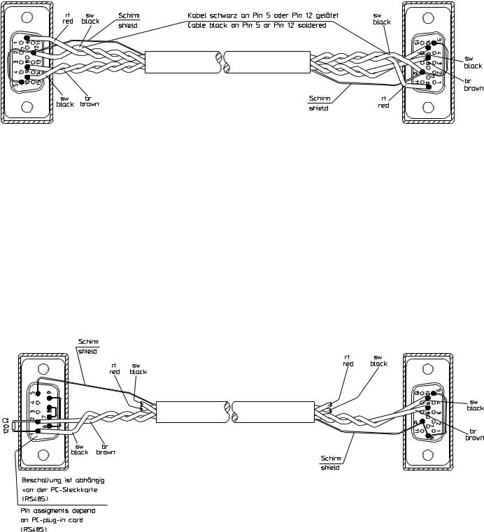
8.7 VERDRAHTUNG FÜR S-MCD BETRIEB |
8.7 WIRING FOR S-MCD OPERATION |
KX 3500, ARTIKELNUMMER 04619, VERDRAHTUNGSPLAN
KX 3500, CATALOG NUMBER 04619, WIRING DIAGRAM
EM 3532-U/PC KABEL, ERSATZTEILNUMMER 75525, VERDRAHTUNGSPLAN
EM 3532-U/PC CABLE, SPARE PART NUMBER 75525, WIRING DIAGRAM
EM 3031, 3032, 3532 07 / 98 - 25
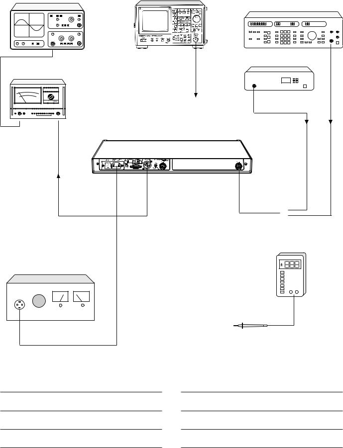
9 PRÜFUND ABGLEICHANWEISUNG |
9 TEST AND ALIGNMENT INSTRUCTIONS |
9.1 MESSAUFBAU |
9.1 TEST SET-UP |
Oszilloskop / Oscilloscope |
Spektrum - Analysator / Spectrum analyser |
|
|
|
HF - Generator / RF generator |
Tracking - Generator / Tracking generator
NF - Multimeter / AF meter
|
-20 |
|
Receiver EM 3031 / EM 3032 / EM 3532-U |
|
siehe Prüfund Abgleichanweisung |
|
Please see test and alignment instructions |
|
DVM |
Trenntransformator / Isolating Transformer |
|
NOTIZEN: |
NOTES: |
|
EM 3031, 3032, 3532 |
|
07 / 98 - 26 |
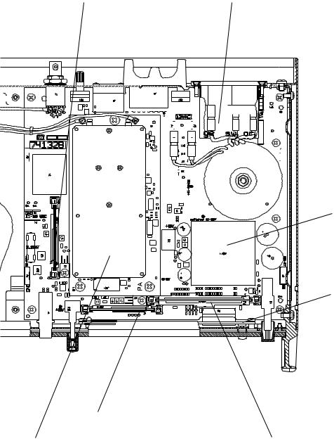
9.2 MODULE |
9.2 ASSEMBLY LOCATION |
|
|
|
|
|
|
|
|
HDP-MODUL (Kapitel 17) |
|
|
|
|
HAUPTPLATINE (Kapitel 11) |
|||||||||||||||||||||||||||||||||||||||||||||
|
|
|
|
|
|
|
|
HDP ASSEMBLY (chapter 17) |
|
|
|
|
MAIN PCB (chapter 11) |
|||||||||||||||||||||||||||||||||||||||||||||
|
|
|
|
|
|
|
|
|
|
|
|
|
|
|
|
|
|
|
|
|
|
|
|
|
|
|
|
|
|
|
|
|
|
|
|
|
|
|
|
|
|
|
|
|
|
|
|
|
|
|
|
|
|
|
|
|
|
|
|
|
|
|
|
|
|
|
|
|
|
|
|
|
|
|
|
|
|
|
|
|
|
|
|
|
|
|
|
|
|
|
|
|
|
|
|
|
|
|
|
|
|
|
|
|
|
|
|
|
|
|
|
|
|
|
|
|
|
|
|
|
|
|
|
|
|
|
|
|
|
|
|
|
|
|
|
|
|
|
|
|
|
|
|
|
|
|
|
|
|
|
|
|
|
|
|
|
|
|
|
|
|
|
|
|
|
|
|
|
|
|
|
|
|
|
|
|
|
|
|
|
|
|
|
|
|
|
|
|
|
|
|
|
|
|
|
|
|
|
|
|
|
|
|
|
|
|
|
|
|
|
|
|
|
|
|
|
|
|
|
|
|
|
|
|
|
|
|
|
|
|
|
|
|
|
|
|
|
|
|
|
|
|
|
|
|
|
|
|
|
|
|
|
|
|
|
|
|
|
|
|
|
|
|
|
|
|
|
|
|
|
|
|
|
|
|
|
|
|
|
|
|
|
|
|
|
|
|
|
|
|
|
|
|
|
|
|
|
|
|
|
|
|
|
|
|
|
|
|
|
|
|
|
|
|
|
|
|
|
|
|
|
|
|
|
|
|
|
|
|
|
|
|
|
|
|
|
|
|
|
|
|
|
|
|
|
|
|
|
|
|
|
|
|
|
|
|
|
|
|
|
|
|
|
|
|
|
|
|
|
|
|
|
|
|
|
|
|
|
|
|
|
|
|
|
|
|
|
|
|
|
|
|
|
|
|
|
|
|
|
|
|
|
|
|
|
|
|
|
|
|
|
|
|
|
|
|
|
|
|
|
|
|
|
|
|
|
|
|
|
|
|
|
|
|
|
|
|
|
|
|
|
|
|
|
|
|
|
|
|
|
|
|
|
|
|
|
|
|
|
|
|
|
|
|
|
|
|
|
|
|
|
|
|
|
|
|
|
|
|
|
|
|
|
|
|
|
|
|
|
|
|
|
|
|
|
|
|
|
|
|
|
|
|
|
|
|
|
|
|
|
|
|
|
|
|
|
|
|
|
|
|
|
|
|
|
|
|
|
|
|
|
|
|
|
|
|
|
|
|
|
|
|
|
|
|
|
|
|
|
|
|
|
|
|
|
|
|
|
|
|
|
|
|
|
|
|
|
|
|
|
|
|
|
|
|
|
|
|
|
|
|
|
|
|
|
|
|
|
|
|
|
|
|
|
|
|
|
|
|
|
|
|
|
|
|
|
|
|
|
|
|
|
|
|
|
|
|
|
|
|
|
|
|
|
|
|
|
|
|
|
|
|
|
|
|
|
|
|
|
|
|
|
|
|
|
|
|
|
|
|
|
|
|
|
|
|
|
|
|
|
|
|
|
|
|
|
|
|
|
|
|
|
|
|
|
|
|
|
|
|
|
|
|
|
|
|
|
|
|
|
|
|
|
|
|
|
|
|
|
|
|
|
|
|
|
|
|
|
|
|
|
|
|
|
|
|
|
|
|
|
|
|
|
|
|
|
|
|
|
|
|
|
|
|
|
|
|
|
|
|
|
|
|
|
|
|
|
|
|
|
|
|
|
|
|
|
|
|
|
|
|
|
|
|
|
|
|
|
|
|
|
|
|
|
|
|
|
|
|
|
|
|
|
|
|
|
|
|
|
|
|
|
|
|
|
|
|
|
|
|
|
|
|
|
|
|
|
|
|
|
|
|
|
|
|
|
|
|
|
|
|
|
|
|
|
|
|
|
|
|
|
|
|
|
|
|
|
|
|
|
|
|
|
|
|
|
|
|
|
|
|
|
|
|
|
|
|
|
|
|
|
|
|
|
|
|
|
|
|
|
|
|
|
|
|
|
|
|
|
|
|
|
|
|
|
|
|
|
|
|
|
|
|
|
|
|
|
|
|
|
|
|
|
|
|
|
|
|
|
|
|
|
|
|
|
|
|
|
|
|
|
|
|
|
|
|
|
|
|
|
|
|
|
|
|
|
|
|
|
|
|
|
|
|
|
|
|
|
|
|
|
|
|
|
|
|
|
|
|
|
|
|
|
|
|
|
|
|
|
|
|
|
|
|
|
|
|
|
|
|
|
|
|
|
|
|
|
|
|
|
|
|
|
|
|
|
|
|
|
|
|
|
|
|
|
|
|
|
|
|
|
|
|
|
|
|
|
|
|
|
|
|
|
|
|
|
|
|
|
|
|
|
|
|
|
|
|
|
|
|
|
|
|
|
|
|
|
|
|
|
|
|
|
|
|
|
|
|
|
|
|
|
|
|
|
|
|
|
|
|
|
|
|
|
|
|
|
|
|
|
|
|
|
|
|
|
|
|
|
|
|
|
|
|
|
|
|
|
|
|
|
|
|
|
|
|
|
|
|
|
|
|
|
|
|
|
|
|
|
|
DC/DC-MODUL (Kapitel 19)
DC/DC ASSEMBLY (chapter 19)
ANZEIGE-MODUL (Kapitel 18)
DISPLAY ASSEMBLY (chapter 18)
SCHALT-MODUL (Kapitel 16)
DIVERSITY ASSEMBLY (chapter 16)
TUNER-MODUL (Kapitel 14 und 20) TUNER ASSEMBLY (chapter 14 and 20)
PROZESSOR-MODUL (Kapitel 21 und 22) PROCESSOR ASSEMBLY (chapter 21 and 22)
EM 3031, 3032, 3532 07 / 98 - 27

9.3 PRÜFUND ABGLEICHANWEISUNG
Nr. |
Messung, |
Signal- |
Vorbereitung, |
Meßpunkt |
Sollwert |
Einsteller |
Bemerkungen |
|
|
Einstellung |
einspeisung |
Geräteeinstellung |
|
|
|
|
|
|
|
|
|
|
|
|
|
|
1 |
Inbetriebnahme |
- |
Netzspannung über |
|
|
|
|
|
|
|
|
Trenntrafo anlegen; |
|
|
|
|
|
|
|
|
S1 "ON", |
|
|
|
|
|
|
|
|
R37 |
"SQUELCH = 0", |
|
|
|
|
|
|
|
R31 |
"AF LEVEL = max." |
|
|
|
|
|
|
|
R30 |
"Headph. = min." |
|
|
|
|
|
|
|
|
|
|
|
|
|
TESTPUNKTE AUF DER HAUPTPLATINE
1.1 |
Betriebsspannung |
- |
DC - Voltmeter |
TP10 |
+ 17 ± 0,5 VDC |
|
|
|
(+ 17 VDC) |
|
|
TP11 - GND |
|
|
|
|
|
|
|
|
|
|
|
1.2 |
Betriebsspannung |
- |
DC - Voltmeter |
TP5 |
+ 5 ± 0,2 VDC |
|
|
|
(+ 5 VDC) |
|
|
|
|
|
|
|
|
|
|
|
|
|
|
1.3 |
Betriebsspannung |
- |
DC - Voltmeter |
TP6 |
+ 8 ± 0,2 VDC |
|
|
|
(+ 8 VDC) |
|
|
|
|
|
|
|
|
|
|
|
|
|
|
1.4 |
Betriebsspannung |
- |
DC - Voltmeter |
TP7 |
- 8 (- 0,2 + 1) VDC |
|
|
|
(- 8 VDC) |
|
|
|
|
|
|
|
|
|
|
|
|
|
|
1.5 |
Boosterspeisung A |
- |
Antennenbuchse |
TP2 nach |
155 ± 25 mV |
|
|
|
Strombegrenzung |
|
(ANT A) kurzschließen; |
TP1 |
|
|
|
|
|
|
DC - Voltmeter |
|
|
|
|
1.6 |
Boosterspeisung B |
- |
Antennenbuchse |
TP4 nach |
155 ± 25 mV |
|
|
|
Strombegrenzung |
|
(ANT B) kurzschließen; |
TP1 |
|
|
|
|
|
|
DC - Voltmeter |
|
|
|
|
|
|
|
|
|
|
|
|
|
|
|
TESTPUNKTE AUF DEM TUNER-MODUL |
|
|
||
|
|
|
|
|
|
|
|
1.7 |
Betriebsspannung |
- |
DC - Voltmeter |
U204 / Pin8 |
+ 5 ± 0,2 VDC |
|
|
|
PLL (+ 5 VDC) |
|
|
|
|
|
|
|
|
|
|
|
|
|
|
2 |
Max. negative |
- |
Mit Schalter "SET" und |
TP10 |
- 4,0 VDC |
|
|
|
Tuningspannung |
|
"DOWN" auf unterste |
|
|
|
|
|
|
|
Empfangsfrequenz |
|
|
|
|
|
|
|
schalten; |
|
|
|
|
|
|
|
DC - Voltmeter |
|
|
|
|
2.1 |
Bereichsgrenzen |
- |
Mit Schalter "SET", "UP" |
TP20 |
- 2,0 …+ 3,8 VDC |
C211 |
Regelsteilheit |
|
der Tuning- |
|
und "DOWN" auf |
|
|
|
UHF (Modul A001): |
|
spannung |
|
oberste und unterste |
|
|
|
5 - 11 MHz / V |
|
|
|
Empfangsfrequenz |
|
|
|
|
|
|
|
schalten; |
|
|
|
VHF (Modul A012): |
|
|
|
DC - Voltmeter |
|
|
|
1,25 MHz / V |
|
|
|
|
|
|
|
|
3 |
1. Oszillator |
- |
Mit Schalter "SET" und |
TP30 |
UHF (Modul A001): |
C228 |
|
|
(Pegel) |
|
"UP" auf mittlere Fre- |
|
- 33 …- 21 dBm |
|
|
|
|
|
quenz des Empfangs- |
|
|
|
|
|
|
|
bereiches einstellen; |
|
VHF (Modul A012): |
|
|
|
|
|
Spektrum - Analysator |
|
- 15 …- 5 dBm |
|
|
3.1 |
1. Oszillator |
- |
wie 3; |
TP30 |
UHF (Modul A001): |
C256 |
FE - Empfangsfrequenz |
|
(Frequenz) |
|
Frequenzmeßgerät |
|
FE - ZF (65,75 MHz) |
|
ZF - Zwischenfrequenz |
|
|
|
|
|
VHF (Modul A012): |
|
|
|
|
|
|
|
FE - ZF (10,7 MHz) |
|
|
|
|
|
|
|
Tol. ± 200 Hz |
|
|
|
|
|
|
|
|
|
|
3.2 |
UHF (Modul A001): |
- |
Spektrum - Analysator: |
TP3 oder |
76,45 MHz, |
T4 |
Kern von T4 eindrehen, |
|
2. Oszillator |
|
CF: 76,45 MHz, |
TP103 |
Tol. ± 3 kHz |
|
bis Frequenzsprung zu |
|
(Frequenz) |
|
SPAN: 10 kHz, |
|
|
|
sehen ist. Kern langsam |
|
|
|
RBW: 1 kHz |
|
|
|
herausdrehen, bis |
|
|
|
|
|
|
|
Frequenz auf |
|
|
|
|
|
|
|
Sollfrequenz springt. |
|
|
|
|
|
|
|
Anschließend Kern |
|
|
|
|
|
|
|
noch 1/2 Drehung |
|
|
|
|
|
|
|
weiter herausdrehen. |
|
|
|
|
|
|
|
Abgleich durch Aus- |
|
|
|
|
|
|
|
und Einschalten |
|
|
|
|
|
|
|
überprüfen. Eventuell |
|
|
|
|
|
|
|
Abgleich wiederholen |
3.3 |
UHF (Modul A001): |
- |
Spektrum - Analysator |
TP3 |
76,45 MHz: max. |
T2 |
|
|
2. Oszillator-Buffer |
|
|
|
Pegel, - 34 …- 26 dBm |
|
|
|
(Pegel Kanal A) |
|
|
|
|
|
|
|
|
|
|
|
65,75 MHz: |
- |
|
|
|
|
|
|
ca. - 32 …- 24 dBm |
|
|
|
|
|
|
|
|
|
|
EM 3031, 3032, 3532 07 / 98 - 28
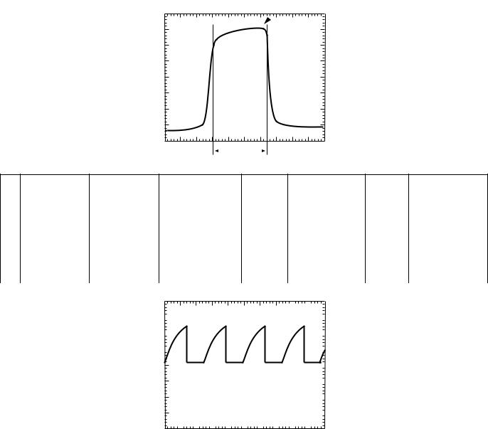
3.4 |
UHF (Modul A001): |
- |
Spektrum - Analysator |
TP103 |
76,45 MHz: max. |
T102 |
|
|
2. Oszillator-Buffer |
|
|
|
Pegel, - 34 …- 26 dBm |
|
|
|
(Pegel Kanal B) |
|
|
|
|
|
|
|
|
|
|
|
65,75 MHz: |
- |
|
|
|
|
|
|
ca. - 32 …- 24 dBm |
|
|
4 |
HF - Eingang |
UHF (Modul A001): |
|
|
UHF (Modul A001): |
|
Boosterspeisung ! |
|
Kanal A |
HF-Signalgenerator |
NF - Voltmeter, |
J3 |
B: ca. 24 MHz, |
C4, C10, |
Signaleinspeisung an |
|
|
an ANT A: Auf |
Oszilloskop |
|
min. Rauschen, |
C15 |
die Antenneneingänge |
|
|
Mittenfrequenz und |
|
|
max. NF-Pegel |
|
mit DC-Trennadapter |
|
|
Bereichsgrenzen ab- |
|
|
|
|
M10 (Best.-Nr. 40838) |
|
|
gleichen (HF bis auf |
|
|
|
|
|
|
|
ca. 5 μV verringern) |
|
|
|
|
|
|
|
VHF (Modul A012): |
|
|
VHF (Modul A012): |
|
|
|
|
Tracking-Generator |
Spektrum - Analysator |
TP1 |
B: 7 MHz, |
C3, C15, |
siehe Abbildung 1 |
|
|
- 47 dBm an ANT A |
|
|
- 67 …- 57 dBm |
C19, C23 |
|
|
|
|
|
|
|
|
|
4.1 |
HF - Eingang |
UHF (Modul A001): |
|
|
UHF (Modul A001): |
C104, C110, |
|
|
Kanal B |
HF-Signalgenerator |
NF - Voltmeter, |
J3 |
B: ca. 24 MHz, |
C115 |
|
|
|
an ANT B: Auf |
Oszilloskop |
|
min. Rauschen, |
|
|
|
|
Mittenfrequenz und |
|
|
max. NF-Pegel |
|
|
|
|
Bereichsgrenzen ab- |
|
|
|
|
|
|
|
gleichen (HF bis auf |
|
|
|
|
|
|
|
ca. 5 μV verringern) |
|
|
|
|
|
|
|
VHF (Modul A012): |
|
|
VHF (Modul A012): |
|
|
|
|
Tracking-Generator |
Spektrum - Analysator |
TP101 |
B: 7 MHz, |
C103, C115, |
siehe Abbildung 1 |
|
|
- 47 dBm an ANT B |
|
|
- 67 …- 57 dBm |
C119, C123 |
|
|
|
|
|
|
|
|
|
dBm
2 dB
- 62 dBm
Abbildung 1
nur VHF (Modul A012)
|
7 MHz |
f |
|
|
|
5 |
ZF - Verstärker |
HF-Signalgenerator Oszilloskop |
|
|
|
D202 / Pin3 |
siehe Abbildung 2 |
ASSY1 |
|||||||||||||
|
und Demodulator |
an ANT A: |
|
|
|
|
|
|
|
|
|
|
|
|
|
|
|
ZF-Modul |
|||
|
Kanal A |
Empfangsfrequenz, |
|
|
|
|
|
|
|
|
|
|
|
|
|
|
|
A002 / L3 |
|||
|
|
HF: 100 μV, |
|
|
|
|
|
|
|
|
|
|
|
|
|
|
|
|
|||
|
|
Hub: 40 kHz, |
|
|
|
|
|
|
|
|
|
|
|
|
|
|
|
|
|||
|
|
Mod: 1 kHz |
|
|
|
|
|
|
|
|
|
|
|
|
|
|
|
|
|||
|
|
|
|
|
|
|
|
|
|
|
|
|
|
|
|
|
|
|
|
|
|
5.1 |
ZF - Verstärker |
HF-Signalgenerator Oszilloskop |
|
|
|
D202 / Pin4 |
siehe Abbildung 2 |
ASSY2 |
|||||||||||||
|
und Demodulator |
an ANT B: |
|
|
|
|
|
|
|
|
|
|
|
|
|
|
|
ZF-Modul |
|||
|
Kanal B |
Empfangsfrequenz, |
|
|
|
|
|
|
|
|
|
|
|
|
|
|
|
A002 / L3 |
|||
|
|
HF: 100 μV, |
|
|
|
|
|
|
|
|
|
|
|
|
|
|
|
|
|||
|
|
Hub: 40 kHz, |
|
|
|
|
|
|
|
|
|
|
|
|
|
|
|
|
|||
|
|
Mod: 1 kHz |
|
|
|
|
|
|
|
|
|
|
|
|
|
|
|
|
|||
|
|
6V |
|
|
|
|
|
|
|
|
|
|
|
|
|
|
|
|
|
|
|
|
|
|
|
|
|
|
|
|
|
|
|
|
|
|
|
|
|
|
|
|
|
|
|
|
|
|
|
|
|
|
|
|
|
|
|
|
|
|
|
|
|
|
|
|
|
|
|
|
|
|
|
|
|
|
|
|
|
|
|
|
|
|
|||
|
|
4V |
|
|
|
|
|
|
|
|
|
|
|
|
|
|
|
|
|
|
|
|
|
|
|
|
|
|
|
|
|
|
|
|
|
|
|
|
|
max. Pegel |
|
||
|
|
|
|
|
|
|
|
|
|
|
|
|
|
|
|
|
|||||
|
|
|
|
|
|
|
|
|
|
|
|
|
|
|
|
|
|
|
|
||
|
|
2V |
|
|
|
|
|
|
|
|
|
|
|
|
|
|
|
|
max. Level |
|
|
|
|
|
|
|
|
|
|
|
|
|
|
|
|
|
|
|
|||||
|
|
0V |
|
|
|
500 s |
|
|
|
|
|
|
|
|
|
Abbildung 2 |
|||||
|
|
|
|
|
|
|
|
|
|
|
|
|
|
||||||||
|
|
|
|
|
|
|
|
|
|
|
|
|
|
||||||||
|
|
-2V |
|
|
|
|
|
|
|
|
|
|
|
|
|||||||
|
|
|
|
|
|
|
|
|
|
|
|
|
|
||||||||
|
|
|
|
|
|
|
|
|
|
||||||||||||
|
|
-4V |
|
|
|
|
|
|
|
|
|
|
|
|
|
|
|
|
|||
|
|
|
|
|
|
|
|
|
|
|
|
|
|
|
|
|
|
||||
|
|
|
|
|
|
|
|
|
|
|
|
|
|
|
|
|
|
||||
|
|
-6V |
|
|
|
|
|
|
|
|
|
|
|
|
|
|
|
|
|||
|
|
|
|
|
|
|
|
|
|
|
|
|
|
|
|
|
|
||||
|
|
|
|
|
|
|
|
|
|
|
|
|
|
|
|
|
|||||
|
|
|
|
|
|
|
|
|
|
|
|
|
|
|
|
|
|
||||
|
|
0 s |
|
|
|
1ms |
|
|
2ms |
|
|||||||||||
EM 3031, 3032, 3532 07 / 98 - 29

5.2 |
Demodulator |
HF-Signalgenerator |
|
NF - Voltmeter, |
|
|
|
J201 / Pin15 |
775 mVeff |
ASSY1 |
|
||||||||||||
|
Kanal A (Pegel) |
an ANT A: |
|
Oszilloskop |
|
|
|
|
|
|
|
|
|
|
|
|
ZF-Modul |
|
|||||
|
|
Empfangsfrequenz, |
|
|
|
|
|
|
|
|
|
|
|
|
|
|
|
|
|
|
|
A002 / R22 |
|
|
|
HF: 100 mV, |
|
|
|
|
|
|
|
|
|
|
|
|
|
|
|
|
|
|
|
|
|
|
|
Hub: 40 kHz, |
|
|
|
|
|
|
|
|
|
|
|
|
|
|
|
|
|
|
|
|
|
|
|
Mod: 1 kHz |
|
|
|
|
|
|
|
|
|
|
|
|
|
|
|
|
|
|
|
|
|
|
|
|
|
|
|
|
|
|
|
|
|
|
|
|
|
|
|
|
|
|
|
|
|
5.3 |
Demodulator |
HF-Signalgenerator |
|
NF - Voltmeter, |
|
|
|
J201 / Pin9 |
775 mVeff |
ASSY2 |
|
||||||||||||
|
Kanal B (Pegel) |
an ANT B: |
|
Oszilloskop |
|
|
|
|
|
|
|
|
|
|
|
|
ZF-Modul |
|
|||||
|
|
Empfangsfrequenz, |
|
|
|
|
|
|
|
|
|
|
|
|
|
|
|
|
|
|
|
A002 / R22 |
|
|
|
HF: 100 mV, |
|
|
|
|
|
|
|
|
|
|
|
|
|
|
|
|
|
|
|
|
|
|
|
Hub: 40 kHz, |
|
|
|
|
|
|
|
|
|
|
|
|
|
|
|
|
|
|
|
|
|
|
|
Mod: 1 kHz |
|
|
|
|
|
|
|
|
|
|
|
|
|
|
|
|
|
|
|
|
|
|
|
|
|
|
|
TESTPUNKTE AUF DEM SCHALT-MODUL |
|
|
|||||||||||||||
|
|
|
|
|
|
|
|
|
|
|
|
|
|
|
|
|
|
|
|
|
|
|
|
6 |
Diversity Schalter |
HF-Signalgenerator |
|
DC - Voltmeter |
|
|
|
P7 |
ca. 5 VDC |
|
LCD Anzeige U1 zeigt |
||||||||||||
|
DIV SW |
an ANT A: |
|
|
|
|
|
|
|
|
|
|
|
|
|
|
(Logisch HI) |
|
"ANT A" an |
||||
|
|
Empfangsfrequenz, |
|
|
|
|
|
|
|
|
|
|
|
|
|
|
|
|
|
|
|
|
|
|
|
HF: 100 mV, |
|
|
|
|
|
|
|
|
|
|
|
|
|
|
|
|
|
|
|
|
|
|
|
Hub: 40 kHz, |
|
|
|
|
|
|
|
|
|
|
|
|
|
|
|
|
|
|
|
|
|
|
|
Mod: 1 kHz |
|
|
|
|
|
|
|
|
|
|
|
|
|
|
|
|
|
|
|
|
|
6.1 |
Diversity Schalter |
HF-Signalgenerator |
|
DC - Voltmeter |
|
|
|
P7 |
ca. 0 VDC |
|
LCD Anzeige U1 zeigt |
||||||||||||
|
DIV SW |
an ANT B: |
|
|
|
|
|
|
|
|
|
|
|
|
|
|
(Logisch LO) |
|
"ANT B" an |
||||
|
|
Empfangsfrequenz, |
|
|
|
|
|
|
|
|
|
|
|
|
|
|
|
|
|
|
|
|
|
|
|
HF: 100 mV, |
|
|
|
|
|
|
|
|
|
|
|
|
|
|
|
|
|
|
|
|
|
|
|
Hub: 40 kHz, |
|
|
|
|
|
|
|
|
|
|
|
|
|
|
|
|
|
|
|
|
|
|
|
Mod: 1 kHz |
|
|
|
|
|
|
|
|
|
|
|
|
|
|
|
|
|
|
|
|
|
|
|
|
|
|
|
|
|
|
|
|
|
|
|
|
|
|
|
|
|
|
|
|
|
6.2 |
Rauschsperre |
HF-Signalgenerator |
|
DC - Voltmeter |
|
|
|
|
|
|
|
|
|
|
|
|
|
Im Regelfall ist P8 |
|||||
|
|
an ANT A: |
|
|
|
|
|
|
|
|
|
|
|
|
|
|
|
|
|
|
|
|
(SQUELCH 180) das |
|
|
Empfangsfrequenz, |
|
|
|
|
|
|
|
|
|
|
|
|
|
|
|
|
|
|
|
|
logisch aktive Signal. |
|
|
HF: 30 mV, |
|
|
|
|
|
|
|
|
|
|
|
|
|
|
|
|
|
|
|
|
In Ausnahmefällen kann |
|
|
Hub: 40 kHz, |
|
|
|
|
|
|
|
|
|
|
|
|
|
|
P6 ¹ P8 |
|
P6 (SQUELCH ZERO) |
||||
|
|
Mod: 1 kHz |
|
|
|
|
|
|
|
|
|
|
|
|
|
|
|
aktiv sein. |
|||||
|
|
|
|
|
|
|
|
|
|
|
|
|
|
|
|
|
|
|
|
|
|
|
Dieses ist abhängig von |
|
SQUELCH ZERO |
|
|
|
|
|
|
|
|
|
|
|
P6 |
Logisch HI (LO) |
|
der Oszillatorlage (ober- |
|||||||
|
und |
|
|
|
|
|
|
|
|
|
|
|
|
|
|
|
|
|
|
|
|
|
oder unterhalb der |
|
SQUELCH 180 |
|
|
|
|
|
|
|
|
|
|
|
P8 |
Logisch LO (HI) |
|
Empfangsfrequenz) und |
|||||||
|
|
|
|
|
|
|
|
|
|
|
|
|
|
|
|
|
|
|
|
|
|
|
wird vom Mikro- |
|
|
|
|
|
|
|
|
|
|
|
|
|
|
|
|
|
|
|
|
|
|
|
prozessor gesteuert |
6.3 |
Rauschsperre |
HF-Signalgenerator |
|
R37 "SQUELCH = max"; |
|
|
|
|
|
|
|
|
|
|
LCD Anzeige U1 zeigt |
||||||||
|
|
an ANT A: |
|
DC - Voltmeter |
|
|
|
|
|
|
|
|
|
|
|
|
|
"MUTE" an |
|||||
|
SQUELCH ZERO |
Empfangsfrequenz, |
|
|
|
|
|
|
|
|
|
|
P6 |
Logisch HI |
|
|
|||||||
|
und |
HF: 30 mV, |
|
|
|
|
|
|
|
|
|
|
|
|
|
|
|
|
|
|
|
|
|
|
SQUELCH 180 |
Hub: 40 kHz, |
|
|
|
|
|
|
|
|
|
|
P8 |
Logisch HI |
|
|
|||||||
|
|
Mod: 1 kHz |
|
|
|
|
|
|
|
|
|
|
|
|
|
|
|
|
|
|
|
|
|
|
|
|
|
|
|
|
|
|
|
|
|
|
|
|
|
|
|
|
|
|
|
|
|
6.4 |
Batterie - Indikator |
HF-Signalgenerator |
|
R37 "SQUELCH = min"; |
P9 |
siehe Abbildung 3 |
|
Dieser Test dient der |
|||||||||||||||
|
|
an ANT A: |
|
Oszilloskop: |
|
|
|
|
|
|
|
|
|
|
|
|
|
Überprüfung des |
|||||
|
|
Empfangsfrequenz, |
|
Volt Div. - 2 V |
|
|
|
|
|
|
|
|
|
|
|
|
|
Signalwegs. Eine Aus- |
|||||
|
|
HF: 100 mV, |
|
Time Div. - 20 ms |
|
|
|
|
|
|
|
|
|
|
|
|
|
sage über die Auswer- |
|||||
|
|
Hub: 3 kHz, |
|
|
|
|
|
|
|
|
|
|
|
|
|
|
|
|
|
|
|
|
tung eines codierten |
|
|
Mod: 5 Hz |
|
|
|
|
|
|
|
|
|
|
|
|
|
|
|
|
|
|
|
|
Signales läßt sich mit |
|
|
|
|
|
|
|
|
|
|
|
|
|
|
|
|
|
|
|
|
|
|
|
dieser Simulation nicht |
|
|
|
|
|
|
|
|
|
|
|
|
|
|
|
|
|
|
|
|
|
|
|
machen. |
|
|
|
6V |
|
|
|
|
|
|
|
|
|
|
|
|
|
|
|
|
|
|
|
|
|
|
|
|
|
|
|
|
|
|
|
|
|
|
|
|
|
|
|
|
|
|
||
|
|
|
|
|
|
|
|
|
|
|
|
|
|
|
|
|
|
|
|
|
|
||
|
|
|
|
|
|
|
|
|
|
|
|
|
|
|
|
|
|
||||||
|
|
|
4V |
|
|
|
|
|
|
|
|
|
|
|
|
|
|
|
|
|
|
|
|
|
|
|
|
|
|
|
|
|
|
|
|
|
|
|
|
|
|
||||||
|
|
|
2V |
|
|
|
|
|
|
|
|
|
|
|
|
|
|
|
|
|
|
|
|
|
|
|
|
|
|
|
|
|
|
|
|
|
|
|
|
|
|
||||||
|
|
|
0V |
|
|
|
|
|
|
|
|
|
|
|
|
Abbildung 3 |
|||||||
|
|
|
|
|
|
|
|
|
|
|
|
|
|
|
|||||||||
|
|
-2V |
|
|
|
|
|
|
|
|
|
|
|
|
|||||||||
|
|
|
|
|
|
|
|
|
|
|
|
|
|
|
|
||||||||
|
|
|
|
|
|
|
|
|
|
|
|
|
|
|
|
||||||||
|
|
|
|
|
|
|
|
|
|
|
|
|
|||||||||||
|
|
-4V |
20 ms |
|
|
|
|
|
|
|
|||||||||||||
|
|
|
|
|
|
|
|
|
|||||||||||||||
|
|
-6V |
|
|
|
|
|
|
|
|
|
|
|
|
|
|
|||||||
|
|
|
|
|
|
|
|
|
|
|
|
|
|
|
|
||||||||
|
|
|
|
|
|
|
|
|
|
|
|
|
|
|
|
|
|
|
|||||
|
|
|
|
|
|
|
|
|
|
|
|
|
|
|
|
|
|
|
|
||||
|
|
|
|
0µs |
|
|
100ms |
|
|
200ms |
|
|
|||||||||||
|
|
|
|
|
|
|
|
|
|
|
|
|
|
|
|
|
|
|
|
|
|
|
|
6.5 |
NF - Ausgang |
HF-Signalgenerator |
|
NF - Voltmeter, |
|
|
|
P19 |
775 mVeff |
|
|
||||||||||||
|
(Pegel) |
an ANT A: |
|
Oszilloskop |
|
|
|
|
|
|
|
|
|
|
|
|
|
|
|||||
|
|
Empfangsfrequenz, |
|
|
|
|
|
|
|
|
|
|
|
|
|
|
|
|
|
|
|
|
|
|
|
HF: 100 mV, |
|
|
|
|
|
|
|
|
|
|
|
|
|
|
|
|
|
|
|
|
|
|
|
Hub: 40 kHz, |
|
|
|
|
|
|
|
|
|
|
|
|
|
|
|
|
|
|
|
|
|
|
|
Mod: 1 kHz |
|
|
|
|
|
|
|
|
|
|
|
|
|
|
|
|
|
|
|
|
|
|
|
|
|
|
|
|
|
|
|
|
|
|
|
|
|
|
|
|
|
|
|
|
|
EM 3031, 3032, 3532 07 / 98 - 30
 Loading...