


Sennheiser ew D1-835-S, ew D1-845-S, ew D1-935, ew D1-945, ew D1-ME2 System Manual
...System Manual

2

Contents
Contents |
|
Important safety instructions . . . . . . . . . . . . . . . . . . . . . . . . . . . . . . . . . . . . . . . |
2 |
Optimum sound the easy way . . . . . . . . . . . . . . . . . . . . . . . . . . . . . . . . . . . . . . . |
5 |
Package contents . . . . . . . . . . . . . . . . . . . . . . . . . . . . . . . . . . . . . . . . . . . . . . . . . . |
6 |
Product overviews . . . . . . . . . . . . . . . . . . . . . . . . . . . . . . . . . . . . . . . . . . . . . . . . . . |
7 |
EM D1 rack receiver . . . . . . . . . . . . . . . . . . . . . . . . . . . . . . . . . . . . . . . . . . . . . . . . . |
7 |
SKM D1, SKM-S D1 and SK D1 transmitters . . . . . . . . . . . . . . . . . . . . . . . . . . . |
11 |
Displays of the transmitters . . . . . . . . . . . . . . . . . . . . . . . . . . . . . . . . . . . . . . . . |
13 |
Optional accessories for the transmitters . . . . . . . . . . . . . . . . . . . . . . . . . . . . . |
13 |
ME 3-II headset microphone . . . . . . . . . . . . . . . . . . . . . . . . . . . . . . . . . . . . . . . . |
14 |
ME 2-2 clip-on microphone . . . . . . . . . . . . . . . . . . . . . . . . . . . . . . . . . . . . . . . . . |
14 |
Putting the products into operation . . . . . . . . . . . . . . . . . . . . . . . . . . . . . . . . . |
15 |
Putting the receiver into operation . . . . . . . . . . . . . . . . . . . . . . . . . . . . . . . . . . |
16 |
Putting the bodypack transmitter into operation . . . . . . . . . . . . . . . . . . . . . . |
22 |
Preparing the headset microphone for use . . . . . . . . . . . . . . . . . . . . . . . . . . . . |
23 |
Attaching the clip-on microphone to clothing . . . . . . . . . . . . . . . . . . . . . . . . . |
23 |
Putting the handheld transmitter into operation . . . . . . . . . . . . . . . . . . . . . . |
24 |
Recharging the accupack . . . . . . . . . . . . . . . . . . . . . . . . . . . . . . . . . . . . . . . . . . . |
25 |
Using the products . . . . . . . . . . . . . . . . . . . . . . . . . . . . . . . . . . . . . . . . . . . . . . . . |
26 |
Switching the devices on or off . . . . . . . . . . . . . . . . . . . . . . . . . . . . . . . . . . . . . . |
26 |
Checking the charge status of the batteries or accupacks . . . . . . . . . . . . . . . |
27 |
Checking the RF signal level . . . . . . . . . . . . . . . . . . . . . . . . . . . . . . . . . . . . . . . . . |
27 |
Muting the bodypack transmitter or the SKM-S D1 handheld transmitter |
28 |
Pairing a receiver with a transmitter . . . . . . . . . . . . . . . . . . . . . . . . . . . . . . . . . |
28 |
Identifying paired devices . . . . . . . . . . . . . . . . . . . . . . . . . . . . . . . . . . . . . . . . . . |
29 |
Using the devices in multi-channel operation . . . . . . . . . . . . . . . . . . . . . . . . . |
29 |
Switching between the standard display and the extended standard display |
29 |
Using the operating menu of the receiver . . . . . . . . . . . . . . . . . . . . . . . . . . . . . |
30 |
Controlling, monitoring or updating devices via the network . . . . . . . . . . . . |
38 |
Cleaning and maintaining the products . . . . . . . . . . . . . . . . . . . . . . . . . . . . . . |
42 |
If a problem occurs ... . . . . . . . . . . . . . . . . . . . . . . . . . . . . . . . . . . . . . . . . . . . . . . |
44 |
Troubleshooting . . . . . . . . . . . . . . . . . . . . . . . . . . . . . . . . . . . . . . . . . . . . . . . . . . . |
44 |
Reacting to messages displayed on the display panel . . . . . . . . . . . . . . . . . . |
45 |
Specifications . . . . . . . . . . . . . . . . . . . . . . . . . . . . . . . . . . . . . . . . . . . . . . . . . . . . . |
46 |
Licenses . . . . . . . . . . . . . . . . . . . . . . . . . . . . . . . . . . . . . . . . . . . . . . . . . . . . . . . . . . |
51 |
Accessories . . . . . . . . . . . . . . . . . . . . . . . . . . . . . . . . . . . . . . . . . . . . . . . . . . . . . . . |
54 |
Manufacturer Declarations . . . . . . . . . . . . . . . . . . . . . . . . . . . . . . . . . . . . . . . . . |
56 |
1

Important safety instructions
Important safety instructions
1.Read these safety instructions and the instruction manuals of the products.
2.Keep these safety instructions and the instruction manuals of the prod-
ucts. Always include these safety instructions and the instruction manuals when passing the products on to third parties.
3.Heed all warnings.
4.Follow all instructions.
5.Do not use the products near water.
6.Only clean the products when they are not connected to the power supply system. Use a dry cloth for cleaning.
7.Do not block any ventilation openings. Install the products in accordance with the instructions given in the instruction manuals.
8.Do not operate near any heat sources such as radiators, stoves, or other apparatus (including amplifiers) that produce heat.
9.Only operate the products from the types of power source specified in the chapter “Specifications” on page 46 and indicated on the power supply unit.
10.Only use the supplied power supply units.
11.Unplug the power supply units from the wall socket,
-to completely disconnect the products from the power supply system,
-during lightning storms or
-when not using the products for long periods of time.
12.Always ensure that the power supply units are
-in a safe operating condition and easily accessible,
-properly plugged into the wall socket,
-only operated within the permissible temperature range,
-not covered or exposed to direct sunlight for longer periods of time in order to prevent heat accumulation.
13.Protect the power cords from being walked on or pinched, particularly at the points where they exit from wall sockets, power supply units and products.
14.Only use attachments, accessories or spare parts specified by Sennheiser
15.Only use the products with the carts, stands, tripods, brackets, or tables
specified by Sennheiser, or sold with the products.
16. When a cart is used, use caution when moving the cart/product combination to avoid injury from tip-over.
17.When using the supplied device feet, do not place the products on delicate surfaces. Delicate surfaces can become discolored or stained when they come into contact with the plastic of the device feet.
18.Refer all servicing to qualified service personnel. Servicing is required when the products have been damaged in any way, liquid has been spilled or objects have fallen into the products, when the products has been exposed to rain or moisture, do not operate normally, or have been dropped.
19.WARNING: To reduce the risk of fire or electric shock, do not expose the products to rain or moisture
20.Do not expose the products to dripping or splashing. Ensure that no objects filled with liquids, such as vases, are placed on the products.
2

Important safety instructions
Risk of fire due to overloading
Do not overload wall outlets and extension cables as this may result in fire and electric shock.
Safety instructions for antennas
Use safety wires to protect the antennas against tipping/dropping.
The safety wires, rope terminations and coupling links must comply in their dimensioning and condition with the regulations and standards of the country in which they are used!
Safety instructions for lithium-ion rechargeable batteries
If abused or misused, the rechargeable batteries may leak. In extreme cases, they may even present a risk of
•explosion,
•fire development,
•heat generation,
•smoke or gas development.
Sennheiser does not accept any liability for damage arising from abuse or misuse.
Keep away from children.
Only charge rechargeable batteries with chargers recommended by Sennheiser.
Observe correct polarity.
Pack/store charged rechargeable batteries so that the terminals cannot contact each other – danger of shorting out/fire hazard.
Do not expose to moisture.
Switch rechargeable battery-powered products off after use.
Only charge rechargeable batteries at ambient temperatures between 10 °C/50 °F and 40 °C/104 °F.
When not using rechargeable batteries for extended periods of time, charge them regularly (about every three months).
Do not mutilate or dismantle.
Do not heat above 60 °C/140 °F, e.g. do not expose to sunlight or throw into a fire.
Immediately remove rechargeable batteries from obviously defective products.
Do not continue to use defective rechargeable batteries.
Only use rechargeable batteries specified by Sennheiser.
3

Important safety instructions
Dispose of rechargeable batteries at special collection points or return them to your specialist dealer.
Store the products in a cool and dry place at room temperature (approx. 20 °C/68 °F).
Remove the rechargeable batteries if the products will not be used for extended periods of time.
Intended use
The microphones, the transmitters, the receiver and the accessories of the Sennheiser 


 system can be combined with each other and have been designed for indoor use (e.g. in rehearsal rooms, studios, theaters and on stages).
In order that music and vocals are transmitted in the best possible quality, the products have to be connected, as described in this instruction manual, to a suitable mixing console or amplifier which, in turn, has to be connected to optimally positioned loudspeakers.
The products can be used for commercial purposes. Intended use includes:
•having read and understood these safety instructions and the instruction manuals of the products
•using the products within the operating conditions and limitations described in these safety instructions and in the instruction manuals of the products.
It is considered improper use when the products are used for any application not named in the instruction manuals of the products.
Sennheiser does not accept liability for damage arising from abuse or misuse of the products and their accessories.
4

Optimum sound the easy way
Optimum sound the easy way
The Sennheiser 


 series consists of high-quality state-of- the-art RF transmission systems with a high level of operational reliability and ease of use. The transmitters and the receiver permit wireless transmission with studio-quality sound.
Features of the 


 series:
•Digital transmission with an excellent transmission range and intelligent signal amplification
•Optimum sound due to preset sound profiles and audio effects:
-low-cut filter
-equalizer
-automatic gain control
-de-esser
•Quick and easy setup and operation due to automatic frequency management and automatic microphone sensitivity adjustment
•Low latency
•Extended dynamic range
•Secure and license-free transmission in the 2.4 GHz frequency band
•Automatic interference management provides optimum protection against sources of interference such as WiFi or Bluetooth
•Long battery life
•Centralized remote control, monitoring and firmware updating via the “Wireless System Remote” (WSR) app or the “Sennheiser D1 SL Updater” software
•Convenient access to help functions via QR codes
5

Package contents
Package contents
|
|
Vocal Sets |
|
Lavalier |
Headmic |
Instrument |
||
Package contents |
|
|
Set |
Set |
Set |
|||
|
|
|
|
|||||
|
ew D1-835-S |
ew D1-845-S |
ew D1-935 |
ew D1-945 |
ew D1-ME2 |
ew D1-ME3 |
ew D1-CI1 |
|
EM D1 |
1 |
1 |
1 |
1 |
1 |
1 |
1 |
|
rack receiver |
||||||||
|
|
|
|
|
|
|
||
SK D1 |
– |
– |
– |
– |
1 |
1 |
1 |
|
bodypack transmitter |
||||||||
|
|
|
|
|
|
|
||
ME 2-2 |
– |
– |
– |
– |
1 |
– |
– |
|
clip-on microphone |
||||||||
|
|
|
|
|
|
|
||
ME 3-II |
– |
– |
– |
– |
– |
1 |
– |
|
headset microphone |
||||||||
|
|
|
|
|
|
|
||
Handheld transmitter |
|
|
|
|
|
|
|
|
with mute switch |
1 |
– |
– |
– |
– |
– |
– |
|
and MMD 835-1 |
||||||||
|
|
|
|
|
|
|
||
microphone head |
|
|
|
|
|
|
|
|
Handheld transmitter |
|
|
|
|
|
|
|
|
with mute switch |
– |
1 |
– |
– |
– |
– |
– |
|
and MMD 845-1 |
||||||||
|
|
|
|
|
|
|
||
microphone head |
|
|
|
|
|
|
|
|
Handheld transmitter |
|
|
|
|
|
|
|
|
with MMD 935-1 |
– |
– |
1 |
– |
– |
– |
– |
|
microphone head |
|
|
|
|
|
|
|
|
Handheld transmitter |
|
|
|
|
|
|
|
|
with MMD 945-1 |
– |
– |
– |
1 |
– |
– |
– |
|
microphone head |
|
|
|
|
|
|
|
|
B 10 battery box |
1 |
1 |
1 |
1 |
– |
– |
– |
|
B 30 battery box |
– |
– |
– |
– |
1 |
1 |
1 |
|
NT 12-4C1 or NT 2-32 |
1 |
1 |
1 |
1 |
1 |
1 |
1 |
|
power supply unit |
||||||||
|
|
|
|
|
|
|
||
CI 1 guitar cable |
– |
– |
– |
– |
– |
– |
1 |
|
Transport case |
1 |
1 |
1 |
1 |
1 |
1 |
1 |
|
|
||||||||
AA size batteries |
2 |
2 |
2 |
2 |
2 |
2 |
2 |
|
(1,5 V) |
||||||||
|
|
|
|
|
|
|
||
1Country-specific versions of the NT 12-4C are available for Europe, the UK, and the USA.
2The NT 2-3 power supply unit is available for all other regions.
6

Product overviews
Product overviews
The transmitters and the receiver are available in different country variants:
• -H variants are available in Europe, the UK and all other countries in which the products are distributed
• -NH variants are available in the Americas, China and Australia
• -NH10 variants are available in Japan and South Korea
The country variant can be found on the packaging and on the type plate as shown on the left.
Only use the country variant permitted for use at the venue.Do not combine devices of different country variants.
EM D1 rack receiver
Operating elements – front panel
1
|
|
|
4 |
5 |
6 |
7 |
|
|
|
|
|
||
|
|
3 |
|
|
|
|
|
2 |
|
|
|
|
|
|
|
|
|
|
|
|
12G4 rod antennas |
for connection to the R-SMA sockets at the rear of the receiver |
|
||||
2PAIR button |
Short-press to identify the paired transmitter (see page 29). |
|
||||
|
Long-press to change the pairing (see page 28). |
|
|
|
||
3Display panel |
For details, see page 9. |
|
|
|
|
|
4Jog dial |
Turn to navigate through the menu, to change settings or to change from the |
|||||
|
standard display to the extended standard display. |
|
|
|
||
|
Press to open the menu or to confirm the entry or selection. |
|
||||
5ESC button |
Short-press to navigate to the next higher level in the menu or to exit a menu |
|||||
|
item without confirming new settings or entries. |
|
|
|
||
|
Long-press to exit the menu and to return to the standard display. |
|||||
6STANDBY button |
Short-press to switch the receiver on. |
|
|
|
|
|
|
Long-press to switch the receiver off. |
|
|
|
|
|
7

Product overviews
7Status LED |
lights up green: |
flashes green:
flashes alternately green and red:

 lights up yellow:
flashes red: 
 lights up red:
A radio link to the transmitter is established. The batteries of the received transmitter are sufficiently charged.
The PAIR button has been short-pressed. Paired devices are being identified.
The PAIR button has been long-pressed. The receiver establishes a radio link to a transmitter whose PAIR button has also been long-pressed.
The received transmitter has been muted with the MUTE switch. In addition, Muted  is displayed on the display panel.
The battery capacity of the received transmitter is only sufficient for approx. 30 minutes of operation.
No radio link to a transmitter. In addition, the background of the display panel
changes back and forth between light and dark and No Link  appears on the display panel.
Operating elements – rear panel
|
|
|
|
|
|
|
|
|
|
|
|
|
|
|
|
|
|
D |
|
|
|
|
|
|
|
|
|
|
|
|
|
|
|
|
|
|
|
|
|
|
|
|
|
|
|
|
|
|
|
|
|
|
|
|
|
|
|
|
|
|
|
|
|
|
|
|
|
|
|
|
|
|
|
|
|
|
|
|
|
|
|
|
|
|
|
|
|
|
|
|
C |
|||
|
|
|
|
|
|
|
|
|
|
|
|
|
|
|
||||
|
|
|
|
|
|
|
|
|
|
0 |
A |
B |
|
|||||
|
|
|
|
|
|
|
|
|
|
|
|
|
|
|||||
|
|
|
|
|
9 |
|
|
|
|
|
|
|
|
|||||
|
|
|
|
|
|
|
|
|
|
|
|
|
|
|||||
|
8 |
|
|
|
|
|
|
|
|
|
|
|
|
|||||
|
|
|
|
|
|
|
|
|
|
|
|
|
|
|
|
|||
8R-SMA socket ANT II |
Antenna input II for connecting a supplied 2G4 rod antenna (for details, see |
|||||||||||||||||
|
page 16) |
|
|
|
|
|
|
|
|
|
|
|
|
|
|
|||
|
|
|
|
|
|
|
|
|
|
|||||||||
9Cable grip |
for the cable of the power supply unit |
|
|
|
|
|
|
|
||||||||||
|
|
|
|
|
|
|
|
|
|
|||||||||
0DC IN socket |
for connection of the power supply unit |
|
|
|
|
|
|
|
||||||||||
|
|
|
|
|
|
|
||||||||||||
A¼" (6.3 mm) jack socket |
Unbalanced audio output for connection to the ¼" (6.3 mm) jack input of the |
|||||||||||||||||
AF OUT UNBAL |
mixing console (for details, see page 20) |
|
|
|
|
|
|
|
||||||||||
|
|
|
|
|
|
|
||||||||||||
BXLR-3 socket AF OUT BAL |
Balanced audio output for connection to the XLR-3 input of the mixing console |
|||||||||||||||||
|
(for details, see page 20) |
|
|
|
|
|
|
|
|
|
|
|
|
|
|
|||
|
|
|
|
|
|
|
||||||||||||
CEthernet socket LAN |
for connecting to a network router or a switch (e.g. to control, monitor and |
|||||||||||||||||
|
update several receivers via a mobile device or a computer (for details, see |
|||||||||||||||||
|
page 20) |
|
|
|
|
|
|
|
|
|
|
|
|
|
|
|||
|
|
|
|
|
|
|
||||||||||||
DR-SMA socket ANT I |
Antenna input I for connecting a supplied 2G4 rod antenna (for details, see |
|||||||||||||||||
|
page 16) |
|
|
|
|
|
|
|
|
|
|
|
|
|
|
|||
8
Product overviews
Displays and icons on the receiver's display panel
Standard display The standard display appears automatically after switch-on or when no button has been pressed on the receiver for a long period of time. The brightness of the standard display automatically dims after a few minutes.
|
|
|
|
|
1 |
|
2 3 |
|
|
4 |
|
|
|
|
|
|
5 |
|
|
|
|
|
|
|
|
||||||||||||||||||||||||
|
|
|
|
|
|
|
|
|
|
|
|
|
|
|
|
|
|
|
|
|
|
|
|
|
|
|
|
|
|
|
|
|
|
|
|
|
|
|
|
|
|
|
|
|
|
|
|
|
|
|
|
|
|
|
|
|
|
|
|
|
|
|
|
|
|
|
|
|
|
|
|
|
|
|
|
|
|
|
|
|
|
|
|
|
|
|
|
|
|||||||||||
|
|
|
|
|
|
|
|
|
EQ |
|
DE-S |
|
|
AGC |
|
|
|
|
|
|
|
|
|
|
|
|
|
|
|
|
|
|
|
|
|
|
|
|
|
||||||||||
|
|
|
|
|
|
|
|
|
|
|
|
|
|
|
|
|
|
|
|
|
|
|
|
|
|
|
|
|
|
|
|
|
|
|
|
|
|
|
|
|
|
|
|
|
|||||
|
|
|
|
|
|
|
|
|
|
|
|
|
|
|
|
|
|
|
|
|
|
|
|
|
NAME |
|
|
|
|
|
|
|
|
|
|
6 |
|||||||||||||
|
|
|
|
|
|
|
|
|
|
|
|
|
|
|
|
|
|
|
|
|
|
|
|
|
|
|
|
|
|
|
|
|
|
|
|||||||||||||||
|
|
|
|
|
|
|
|
|
|
|
|
|
|
|
|
|
|
|
|
|
|
|
|
10 h |
|
|
|
|
|
|
|
|
|
|
|
|
|
|
|
|
|
|
|
|
|
|
|
|
|
|
|
|
|
|
|
|
|
|
|
|
|
|
|
|
|
|
|
|
|
|
|
|
|
|
|
|
|
|
|
|
|
|
|
|
|
|
|
|
|
|
|
|
|
|
|
|
|
|
|
|
|
|
|
|
|
B |
|
|
|
|
|
|
|
|
|
|
|
|
|
|
|
A |
|
|
|
|
|
|
|
|
|
|
|
|
|
|
|
|
|||||||||||
|
|
|
|
|
|
|
|
|
|
|
|
|
|
|
|
|
|
|
|
0 9 8 |
|
|
|
|
7 |
|
|
|
|
|
|
|
|
||||||||||||||||
1Equalizer |
|
If one of the equalizer functions is activated, EQ appears in inverse on the |
|||||||||||||||||||||||||||||||||||||||||||||||
|
|
|
|
|
|
standard display (for details, see page 32). |
|||||||||||||||||||||||||||||||||||||||||||
|
|
|
|
|
|||||||||||||||||||||||||||||||||||||||||||||
2De-esser |
|
If one of the de-esser functions is activated, DE-S appears in inverse on the |
|||||||||||||||||||||||||||||||||||||||||||||||
|
|
|
|
|
|
standard display (for details, see page 33). |
|||||||||||||||||||||||||||||||||||||||||||
|
|
|
|
|
|||||||||||||||||||||||||||||||||||||||||||||
3Auto gain control |
|
If one of the compression functions is activated, AGC appears in inverse on the |
|||||||||||||||||||||||||||||||||||||||||||||||
|
|
|
|
|
|
standard display (for details, see page 33). |
|||||||||||||||||||||||||||||||||||||||||||
|
|
|
|
|
|||||||||||||||||||||||||||||||||||||||||||||
4MUTE |
|
The received transmitter is not muted, but can be muted at any time (for |
|||||||||||||||||||||||||||||||||||||||||||||||
|
|
|
|
|
|
details, see page 28). |
|
|
|
|
|
|
|
|
|
|
|
|
|
|
|
|
|
|
|
|
|
|
|
||||||||||||||||||||
|
|
|
|
|
|
|
|||||||||||||||||||||||||||||||||||||||||||
|
|
|
|
|
|
The received transmitter is muted. In addition, the status LED lights up yellow. |
|||||||||||||||||||||||||||||||||||||||||||
|
|
|
|
|
|
|
|||||||||||||||||||||||||||||||||||||||||||
|
|
|
|
|
|
The received transmitter cannot be muted because its MUTE switch is deacti- |
|||||||||||||||||||||||||||||||||||||||||||
|
|
|
|
|
|
vated (for details see page 35). |
|
|
|
|
|
|
|
|
|
|
|
||||||||||||||||||||||||||||||||
|
|
|
|
|
|||||||||||||||||||||||||||||||||||||||||||||
5Audio level display |
|
The audio level is automatically optimally adjusted. |
|||||||||||||||||||||||||||||||||||||||||||||||
|
|
|
|
|
|||||||||||||||||||||||||||||||||||||||||||||
6Extended standard display |
The extended standard display appears when you turn the jog dial to the left |
||||||||||||||||||||||||||||||||||||||||||||||||
|
|
|
|
|
|
(see page 10). The above shown standard display appears again after 10 sec- |
|||||||||||||||||||||||||||||||||||||||||||
|
|
|
|
|
|
onds or when you turn the jog dial to the right. |
|||||||||||||||||||||||||||||||||||||||||||
|
|
|
|
|
|||||||||||||||||||||||||||||||||||||||||||||
76-segment RF signal level display |
|
Displays the field strength of the received signal. The 6-segment RF signal |
|||||||||||||||||||||||||||||||||||||||||||||||
|
|
|
|
|
|
level display is also shown on the transmitter display panel. |
|||||||||||||||||||||||||||||||||||||||||||
|
|
|
|
|
|
|
|||||||||||||||||||||||||||||||||||||||||||
8RF output power of the receiver‘s |
|
|
|
Medium RF output |
|
Displayed by the -H and -NH10 country variants. |
|||||||||||||||||||||||||||||||||||||||||||
|
|
|
|||||||||||||||||||||||||||||||||||||||||||||||
back channel |
|
|
|
power |
|
|
|
|
|
|
|
|
|
|
|
|
|
|
|
|
|
|
|
|
|
|
|
|
|||||||||||||||||||||
|
|
|
|
|
|
|
|
|
|
|
|
|
|
|
|
|
|
|
|
|
|
|
|
|
|
||||||||||||||||||||||||
|
|
|
|
|
|
|
|
||||||||||||||||||||||||||||||||||||||||||
|
|
|
|
|
|
High RF output power |
Only displayed by the -NH country variant. |
||||||||||||||||||||||||||||||||||||||||||
|
|
|
|
|
|
||||||||||||||||||||||||||||||||||||||||||||
|
|
|
|
|
|||||||||||||||||||||||||||||||||||||||||||||
|
|
|
|
|
|
|
|
|
|
|
|
|
|
|
|
|
|
|
|
|
|
|
|
|
|
|
|
|
|
|
|
|
|
|
|
|
|
|
|
|
|
|
|
|
|
|
|
|
|
9Lock mode |
|
Open padlock icon: The lock mode is temporarily deactivated and the receiver |
|||||||||||||||||||||||||||||||||||||||||||||||
|
|
|
|
|
|
can be operated as usual. |
|
|
|
|
|
|
|
|
|
|
|
||||||||||||||||||||||||||||||||
|
|
|
|
|
|
|
|||||||||||||||||||||||||||||||||||||||||||
|
|
|
|
|
|
Locked padlock icon: The lock mode is activated. Press and hold the jog dial to |
|||||||||||||||||||||||||||||||||||||||||||
|
|
|
|
|
|
temporarily deactivate the lock mode. To permanently deactivate the lock |
|||||||||||||||||||||||||||||||||||||||||||
|
|
|
|
|
|
mode, see page 34. |
|
|
|
|
|
|
|
|
|
|
|
|
|
|
|
|
|
|
|
|
|
|
|
|
|||||||||||||||||||
|
|
|
|
|
|
|
|||||||||||||||||||||||||||||||||||||||||||
|
|
|
|
|
|
If no padlock icon is displayed, the lock mode is permanently deactivated (for |
|||||||||||||||||||||||||||||||||||||||||||
|
|
|
|
|
|
details, see page 34). |
|
|
|
|
|
|
|
|
|
|
|
|
|
|
|
|
|
|
|
|
|
|
|
||||||||||||||||||||
|
|
|
|
|
|
|
|
|
|
|
|
|
|
|
|
||||||||||||||||||||||||||||||||||
0Name of the radio link |
|
To change this name, see page 32. |
|
|
|
|
|
|
|
|
|
|
|
||||||||||||||||||||||||||||||||||||
|
|
|
|
|
|||||||||||||||||||||||||||||||||||||||||||||
ARemaining battery life of the received |
|
This information is only displayed when the transmitter is powered via the |
|||||||||||||||||||||||||||||||||||||||||||||||
transmitter |
|
optional accupack (for details, see page 27). |
|||||||||||||||||||||||||||||||||||||||||||||||
|
|
|
|
|
|||||||||||||||||||||||||||||||||||||||||||||
B7-segment display of the transmitter‘s |
|
The 7-segment battery or accupack capacity display is also shown on the |
|||||||||||||||||||||||||||||||||||||||||||||||
battery or accupack capacity |
|
transmitter display panel (for details, see page 27). |
|||||||||||||||||||||||||||||||||||||||||||||||
|
|
|
|
|
|
|
|
|
|
|
|
|
|
|
|
|
|
|
|
|
|
|
|
|
|
|
|
|
|
|
|
|
|
|
|
|
|
|
9 |
||||||||||
|
|
|
|
|
|
|
|
|
|
|
|
|
|
|
|
|
|
|
|
|
|
|
|
|
|
|
|
|
|
|
|
|
|
|
|
|
|
|
|||||||||||

Product overviews
Extended standard display The extended standard display appears when you turn the jog dial to the left.
|
|
|
|
|
|
|
|
|
Audio out: |
|
|
|
10 dB |
|
|
|
|
|
|
|
|
|
|
|
|
|
|
|
|
|
|
|
|
|
|||
|
|
|
|
|
|
|
|
|
|
|
|
|
|
|
|
|||
|
|
|
|
|
|
|
|
|
|
|
|
|
|
|
|
|||
|
|
|
|
|
|
|
|
|
845 |
|
|
|
|
|
|
C |
||
|
|
|
|
|
|
|
|
|
|
|
|
|
|
|
||||
|
|
|
|
|
|
|
|
|
Low cut filter: |
Off |
|
|||||||
|
|
|
|
|
|
|
|
|
|
|
|
|
||||||
|
|
|
|
|
|
|
|
|
|
|
|
|
||||||
|
|
|
|
|
|
|
|
|
|
|
|
|
|
|
|
|
|
|
|
|
|
|
|
|
|
|
|
|
|
|
|
|
|
|
|
|
|
|
|
|
|
|
|
|
F |
E |
|
|
|
|
|
|
|
|
|
|
|
|
|
|
|
|
|
D |
|
|
|
|
|
|
|||||
CPick-up pattern of the microphone used |
|
For details, see page 24. |
||||||||||||||||
|
|
|
|
|
|
|
|
|
|
|
|
|
|
|
|
|
||
DStatus of the low-cut filter (ON/OFF) |
For details, see page 32. |
|||||||||||||||||
|
|
|
|
|
|
|
|
|
|
|
|
|
|
|
|
|
||
EOutput level of the receiver in dB |
|
|
For details, see page 34. |
|||||||||||||||
|
|
|
|
|
|
|
|
|
|
|
|
|
|
|
|
|||
FProduct name of the microphone head used |
For details, see page 24. |
|||||||||||||||||
Power supply units for the receiver |
|
NT 2-3 |
NT 12-4C |
|
1 |
2 |
3 |
|
1NT 2-3 |
|
Not available in Europe, the UK, and the USA. |
|
power supply unit |
|
|
|
|
|
|
|
2Interchangeable |
|
for plugging onto the NT 2-3 |
|
country adapters |
|
|
|
|
|
|
|
3NT 12-4C |
|
Country-specific variants are available in Europe, |
|
power supply unit |
|
the UK, and the USA. |
|
10

Product overviews
SKM D1, SKM-S D1 and SK D1 transmitters
Operating elements of the SKM D1 and SKM-S D1 handheld transmitters
1
2
3
4
5
6
SKM-S D1 |
SKM D1 |
|
Mic |
|
Mute |
1Unscrewable microphone head
2Display panel
3MUTE switch
4ON/OFF buttonwith status LED

 lights up green:
flashes green:
flashes alternately green and red:

 lights up yellow:
flashes red: 
 lights up red:
5PAIR button
6Antenna
For details, see page 24.
Do not cover the microphone head during transmission to avoid changing the characteristics of the pick-up pattern.
For details, see page 13.
for muting the SKM-S D1 handheld transmitter (for details, see page 28)
Short-press to switch the handheld transmitter on.
Long-press to switch the handheld transmitter off (for details, see page 26).
A radio link to the receiver is established. The batteries of the handheld transmitter are sufficiently charged.
The PAIR button has been short-pressed. Paired devices are being identified.
The PAIR button has been long-pressed. The handheld transmitter establishes a radio link to a receiver whose PAIR button has also been long-pressed.
The SKM-S D1 handheld transmitter has been muted with the MUTE switch. In addition, Muted  is displayed on the display panel.
The battery capacity of the handheld transmitter is only sufficient for approx. 30 minutes of operation.
No radio link to a receiver. In addition, No Link  is displayed on the display panel.
Short-press to identify the paired receiver (see page 29).
Long-press to change the pairing (see page 28).
Do not touch the antenna during transmission to avoid a reduction in the transmission range.
11
Product overviews
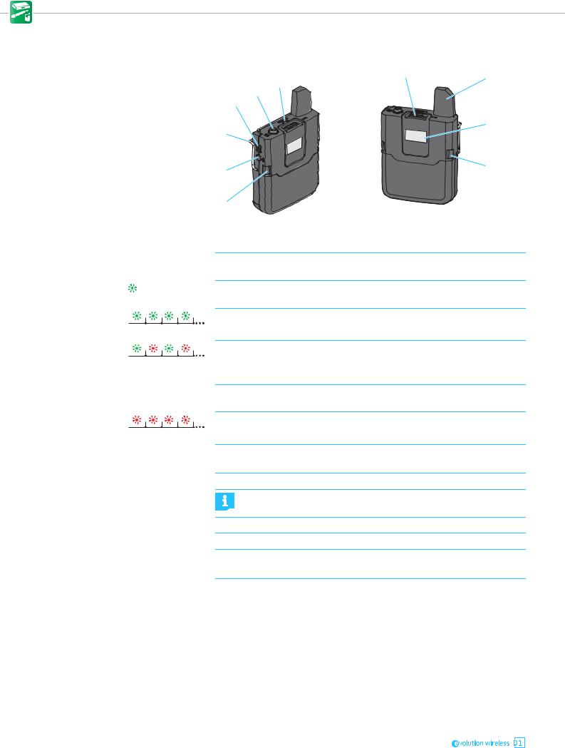
1ON/OFF button
2 3.5 mm jack socket Mic/Line
3Status LED |
lights up green: |
flashes green:
flashes alternately green and red:

 lights up yellow:
flashes red: 
 lights up red:
4MUTE switch
5Antenna
6Display panel
7Catches
8PAIR button
9Belt clip
Operating elements of the SK D1 bodypack transmitter
|
4 |
5 |
3 |
|
|
|
|
2
1
6
9
8 |
7 |
|
|
7 |
|
Short-press to switch the bodypack transmitter on.
Long-press to switch the bodypack transmitter off (for details, see page 26).
for connecting the clip-on or headset microphone
A radio link to the receiver is established. The batteries of the bodypack transmitter are sufficiently charged.
The PAIR button has been short-pressed. Paired devices are being identified (for details, see page 29).
The PAIR button has been long-pressed. The bodypack transmitter establishes a radio link to a receiver whose PAIR button has also been long-pressed (for details, see page 28).
The bodypack transmitter has been muted with the MUTE switch. In addition, Muted  is displayed on the display panel (for details, see page 28).
The battery capacity of the bodypack transmitter is only sufficient for approx. 30 minutes of operation.
No radio link to a receiver. In addition, No Link  is displayed on the display panel.
for muting the bodypack transmitter (for details, see page 28)
Do not touch the antenna during transmission to avoid a reduction in the transmission range.
For details, see page 13.
Press simultaneously to release the battery box or the accupack.
Short-press to identify the paired receiver (see page 29).
Long-press to change the pairing (see page 28).
For details, see page 22.
12

Product overviews
5
4 


 123
123


 6
6
Displays of the transmitters
1 |
|
|
|
|
|
|
|
|
|
|
|
NAME |
|
|
|
|
|
||||||||||||||
2 |
|
|
|
|
|
|
|
|
|
|
|
|
|
|
|
|
|
|
|
|
|
|
|
|
|
|
|
|
|
|
3 |
|
|
|
|
|
|
|
|
|
|
|
|
|
|
|
|
|
|
|
|
|
|
|
|
|
|
|
|
|
|
||
|
|
|
|
|
|
|
|
|
|
|
|
|
|
|
|
|
|
|
|
|
|
|
|
|
|
|
|
|
|
|
|
1Name of the radio link |
|
|
For details, see page 32. |
||||||||||||||||||||||||||||
27-segment display of the battery For details, see page 27. or accupack capacity
36-segment RF signal level display Displays the field strength of the transmitted signal at the receiver.
Optional accessories for the transmitters
BA 10 accupack for the SKM D1 or SKM-S D1 handheld transmitter
1Micro USB socket with |
for charging the accupack with any USB power sup- |
cover flap |
ply/charger (for details, see page 25) |
2Charge status LED |
|
lights up red: The accupack is being charged |
|
|
|
|
lights up green: The accupack is fully charged |
|
|
3Contact surfaces |
for powering the handheld transmitter |
|
|
4Accupack |
contains the Li-Ion rechargeable battery |
|
|
5Catches |
Press simultaneously to release the accupack from |
|
the handheld transmitter. |
|
|
6Charging contacts |
for charging the accupack in the charging unit |
1
5 |
4 |
3 |
|
|
2 |
||
|
|
||
|
|
|
1 |
3


 2
2
BA 30 accupack for the SK D1 bodypack tranmsitter
1Contact surfaces |
for powering the bodypack transmitter |
|
|
|
|
2Accupack |
|
contains the Li-Ion rechargeable battery |
|
|
|
3Charging contacts |
for charging the accupack in the charging unit |
|
|
|
|
4Micro USB socket with |
|
for charging the accupack with any USB power sup- |
cover flap |
|
ply/charger (for details, see page 25) |
5Charge status LED |
|
|
|
lights up red: The accupack is being charged |
|
|
|
|
|
|
lights up green: The accupack is fully charged |
USB power supply/charger for charging the accupacks |
||
1NT 5-10-U |
USB power supply/charger (country-specific) |
|
|
for charging the accupacks |
|
|
|
|
2USB connector |
for connection to the USB power supply/charger |
|
(type A) |
|
|
|
|
|
3Micro USB connector |
for connection to an accupack |
|
13

Product overviews
ME 3-II headset microphone
|
7 |
|
|
|
|
|
|
|
|
|
|
|
1 |
|
6 |
5 |
4 |
3 |
2 |
|
|
|
|||||
|
1Microphone capsule with lateral sound inlet and cardioid pick-up pattern |
|||||
|
with windshield |
|
|
|
|
|
|
2Flexible microphone for precise positioning of the microphone at the corner |
|||||
|
boom |
|
|
of the mouth |
|
|
|
3Ear hooks |
|
for a secure fit on the ears |
|
||
|
4Clips |
|
|
for attaching the connection cable to the ear hook |
||
|
5Connection cable |
|
with lockable 3.5 mm jack plug |
|||
|
6Neckband |
|
for a secure fit on the head |
|
||
|
7Neckband padding |
|
for a comfortable fit, adjustable in length with a Velcro |
|||
|
|
|
|
fastener |
|
|
|
ME 2-2 clip-on microphone |
|
||||
1 |
1Microphone capsule with |
should be pointed towards the mouth |
||||
|
windshield |
|
|
|
|
|
2 |
2Anti-kink protection |
|
to prevent cable damage |
|||
3 |
3Connection cable (1.6 m) |
with lockable 3.5 mm jack plug for connection to |
||||
|
|
|
|
|
the bodypack transmitter |
|
Supplied with microphone clip to attach the clip-on microphone to clothing.
14
Putting the products into operation
Putting the products into operation
Avoiding sources of interference Featuring automatic interference management, the devices are capable of avoiding interfering signals at any time by automatically moving together to unused frequencies in the 2.4 GHz frequency band, without any audio interruption. However, the number of usable radio links is reduced if there are active sources of interference in the vicinity of the devices.
Switch off possible sources of interference operating in the 2.4 GHz frequency band.
Possible sources of interference use e.g. WiFi or Bluetooth.
Infrared remote controls and headphones, DECT headphones and UHF radio links (e.g. Sennheiser evolution wireless G3) do not represent a source of interference and can remain switched on.
You can identify and locate sources of interference using a WiFi scanning tool.
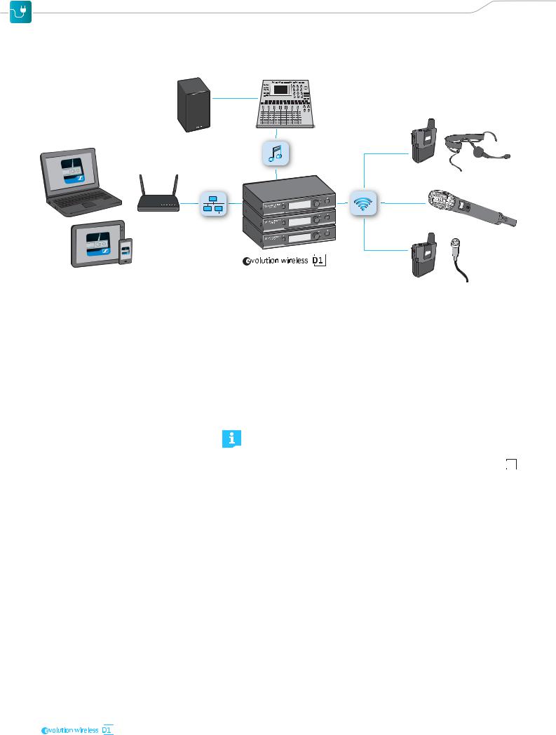
If you want to use WiFi while operating devices of the 


 series, use a dual-band WiFi router and deactivate its 2.4 GHz frequency band in order to minimize interference to the radio links.
If conditions are optimal, you can operate up to 15 radio links simultaneously (for details, see “Using the devices in multi-channel operation” on page 29).
Direct line of sight recommended Walls and other obstacles will reduce the range. Therefore, there should always be a direct line of sight between the transmitting antenna and the receiving antennas of a radio link. To ensure this, you can mount the antennas of the receiver in different ways.
•When using the EM D1 as a stand-alone receiver, you can mount the supplied 2G4 rod antennas to the rear of the receiver (see page 16).
•When rack-mounting the receiver, you should use the GA 4 rack-mount kit to mount the receiver antennas to the front of the rack (see page 19).
15

Putting the products into operation
Putting the receiver into operation
Fitting the device feet
ATTENTION
Risk of staining of furniture surfaces!
Some furniture surfaces have been treated with varnish, polish or synthetics which might cause stains when they come into contact with other synthetics. Despite a thorough testing of the synthetics used by us, we cannot rule out the possibility of staining.
Do not place the receiver on delicate surfaces.
Do not fit the device feet when mounting the receiver into a rack.
Clean the recesses for the device feet at base of the receiver.
Fit the device feet to the recesses of the receiver.
Place the receiver on a flat, horizontal surface.
The device feet will adhere reliably to the receiver only after some time. Avoid moving the receiver during this time.
Mounting the rack mount “ears”
The rack mount “ears” are designed to help protect the operating elements from damage or deformation, e.g. if the receiver is dropped.
Therefore, always fasten the rack mount “ears”, even if you do not want to rack mount the receiver.
To fasten the rack mount “ears”:
1
Unscrew and remove the two recessed head screws on each side of the receiver.
Secure the rack mount “ears” 1 to the sides of the receiver using the previously removed recessed head screws.
Connecting the rod antennas to the receiver
The supplied 2G4 rod antennas can be mounted quickly and easily. The rod antennas are suitable for all applications where – good reception conditions provided – a wireless transmission system is to be used without a large amount of installation work
16
 Loading...