


EM_550_G2.book Seite 37 Donnerstag, 27. November 2003 1:33 13
EM550
Instructions for use
37

EM_550_G2.book Seite 38 Donnerstag, 27. November 2003 1:33 13
Thank you for choosing Sennheiser!
We have designed this product to give you reliable operation over many years. Over half a century of accumulated expertise in the design and manufacture of high-quality electro-acoustic equipment have made Sennheiser a world-leading company in this field.
Please take a few moments to read these instructions carefully, as we want you to enjoy your new Sennheiser product quickly and to the fullest.
38

EM_550_G2.book Seite 39 Donnerstag, 27. November 2003 1:33 13
Contents |
|
The EM 550 G2 twin receiver ............................................................................... |
40 |
The channel bank system ............................................................................................. |
40 |
Safety instructions ................................................................................................. |
41 |
Delivery includes ..................................................................................................... |
41 |
Areas of application ............................................................................................... |
42 |
Overview of operating controls ........................................................................... |
43 |
Indications and displays ........................................................................................ |
44 |
Indications and displays of the receivers ................................................................... |
44 |
Remote displays of an ew 500 G2 transmitter ......................................................... |
44 |
Preparing the receiver for use ............................................................................. |
46 |
Mounting the receiver feet ........................................................................................... |
46 |
Connecting the antennas .............................................................................................. |
46 |
Connecting and mounting remote antennas ............................................................ |
46 |
Daisy-chaining up to eight twin receivers ................................................................. |
47 |
Connecting the mains cable ......................................................................................... |
47 |
Connecting the amplifier/mixing console .................................................................. |
48 |
Service interfaces ........................................................................................................... |
48 |
Mounting the twin receiver into a 19” rack .............................................................. |
48 |
Mounting the antennas ................................................................................................. |
48 |
Using the twin receiver ......................................................................................... |
50 |
Switching the twin receiver on/off ............................................................................. |
50 |
Connecting the headphones/adjusting the volume ................................................ |
50 |
Activating/deactivating the lock mode ..................................................................... |
50 |
The operating menu ............................................................................................... |
51 |
The buttons ..................................................................................................................... |
51 |
Overview of menus ......................................................................................................... |
51 |
Working with the operating menu ............................................................................. |
52 |
Operating menu of the receiver RX A or RX B of the twin receiver ...................... |
53 |
Adjustment tips for the operating menu .......................................................... |
56 |
Switching between channel banks ............................................................................. |
56 |
Switching between the channels in a channel bank ............................................... |
56 |
Selecting the frequencies to be stored |
|
in the channel bank “U” ....................................................................................................... |
56 |
Scanning the channel banks for free channels ......................................................... |
57 |
Multi-channel operation ................................................................................................ |
58 |
Adjusting the audio output level ................................................................................ |
58 |
Adjusting the squelch threshold ................................................................................. |
58 |
Doing the soundcheck ................................................................................................... |
59 |
Selecting the standard display .................................................................................... |
60 |
Entering a name .............................................................................................................. |
60 |
Loading the factory-preset default settings ............................................................. |
61 |
Activating/deactivating the pilot tone evaluation .................................................. |
61 |
Activating/deactivating the lock mode ..................................................................... |
61 |
Using the equalizer ........................................................................................................ |
62 |
Adjusting the contrast of the graphic display .......................................................... |
62 |
Exiting the operating menu .......................................................................................... |
62 |
Troubleshooting ...................................................................................................... |
63 |
Error checklist .............................................................................................. |
63 |
Recommendations and tips .......................................................................................... |
64 |
Care and maintenance ........................................................................................... |
64 |
Additional information .......................................................................................... |
65 |
HDX noise reduction ....................................................................................................... |
65 |
Wireless transmission systems ................................................................................... |
65 |
Squelch ............................................................................................................................. |
66 |
Diversity reception ......................................................................................................... |
67 |
Specifications .......................................................................................................... |
68 |
Connector assignment ................................................................................................... |
69 |
Accessories .............................................................................................................. |
69 |
|
39 |

EM_550_G2.book Seite 40 Donnerstag, 27. November 2003 1:33 13
The EM 550 G2 twin receiver
The EM 550 G2 twin receiver consists of two complete true diversity receivers in a single 19” rack housing. The two receivers can be operated independently from each other. The EM 550 G2 has an integrated antenna splitter, enabling you to daisy-chain up to eight twin receivers.
The EM 550 G2 can be combined with transmitters of the ew 500 G2 series to make high-quality state-of-the-art RF transmission systems for professional applications. The transmitters and the twin receiver have a high level of operational reliability and are extremly user-friendly. The excellent transmission reliability is based on the use of
yfurther optimized PLL synthesizer and microprocessor technology,
ythe HDX noise reduction system,
ythe pilot tone squelch control,
ythe true diversity technology (rack-mount receiver only),
yand the scan function for scanning the channel banks for free channels.
The channel bank system
The twin receiver is available in five UHF frequency ranges with 1,440 receiving frequencies per frequency range. Please note: Frequency usage is different for each country. Your Sennheiser agent will have all the necessary details on the available legal frequencies for your area.
Range A: |
518 to 554 MHz |
Range B: |
626 to 662 MHz |
Range C: |
740 to 776 MHz |
Range D: |
786 to 822 MHz |
Range E: |
830 to 866 MHz |
Each receiver of the EM 550 G2 has nine channel banks with up to 20 switchable channels each.
|
|
channel 1 |
|
preset frequency |
|
|
|
||
|
|
|
|
|
|
|
|
|
|
|
|
channel 2 |
|
preset frequency |
channel bank 1...8 |
|
|
||
|
|
|
|
|
|
|
|
|
|
|
|
|
|
|
|
|
|
|
|
|
|
channel 20 |
|
preset frequency |
|
|
|
||
|
|
|
|
|
|
|
|
|
|
|
|
channel 1 |
|
freely selectable frequency |
|
|
|
||
|
|
|
|
|
|
|
|
|
|
|
|
channel 2 |
|
freely selectable frequency |
|
|
|
||
|
|
|
channel bank U
channel 20 |
|
freely selectable frequency |
|
||
|
|
|
Each of the channels in the channel banks “1” to “8” has been factory-preset to a receiving frequency (see enclosed frequency table). These receiving frequencies cannot be changed but have been preset so that e.g. countryspecific regulations on frequency usage are taken into account.
40

EM_550_G2.book Seite 41 Donnerstag, 27. November 2003 1:33 13
The channel bank “U” (user bank) allows you to store your selection out of 1,440 receiving frequencies that are freely selectable within the preset frequency range.
Safety instructions
Never open an electronic unit! If units are opened by customers in breach of this instruction, the warranty becomes null and void.
Keep the unit away from central heating radiators and electric heaters. Never expose it to direct sunlight.
Use the unit in dry rooms only.
Use a damp cloth for cleaning the unit. Do not use any cleansing agents or solvents.
Attention! High Volume!
This is a professional transmission system. Commercial use is subject to the rules and regulations of the trade association responsible. Sennheiser, as the manufacturer, is therefore obliged to expressly point out possible health risks arising from use.
The sound pressure at the headphone outputs of the twin receiver may exceed 85 dB(A). 85 dB(A) is the sound pressure corresponding to the maximum permissible volume which is by law (in some countries) allowed to affect your hearing for the duration of a working day. It is used as a basis according to the specifications of industrial medicine. Higher volumes or longer durations can damage your hearing. At higher volumes, the duration must be shortened in order to prevent damage. The following are sure signs that you have been subjected to excessive noise for too long a time:
yYou can hear ringing or whistling sounds in your ears.
yYou have the impression (even for a short time only) that you can no longer hear high notes.
Delivery includes
The packaging contains the following items:
y1 EM 550 G2 twin receiver
y1 mains cable
y2 telescopic antennas
y1 rack adapter
yInstructions for use
41

EM_550_G2.book Seite 42 Donnerstag, 27. November 2003 1:33 13
Areas of application
The EM 550 G2 twin receiver can be combined with transmitters of the ew 500 G2 series (SK 500 G2 bodypack transmitter, SKM 500 G2 radiomicrophone or SKP 500 G2 plug-on transmitter). The transmitters are available in the same five UHF frequency ranges and are equipped with the same channel bank system with factory-preset frequencies. An advantage of the factory-preset frequencies is that
ya transmission system is ready for immediate use after switch-on,
yseveral transmission systems can be operated simultaneously on the preset frequencies without causing intermodulation interference.
Together with a matching transmitter and a microphone, the receiver is suitable for the following areas of applications:
Transmitter and suitable accessories |
Area of application |
|
(to be ordered separately) |
|
|
SK 500 G2 |
with ME 2 clip-on microphone |
Theater, |
|
(condenser, omni-directional) |
presentations |
|
with ME 4 clip-on microphone |
Theater, |
|
(condenser, cardioid) |
PA applications |
|
with ME 3 headmic |
Vocals, sports |
|
(condenser, super-cardioid) |
(aerobic) |
|
with instrument cable |
Using instruments |
|
|
wirelessly |
SKM 500 G2 |
with MD 835 microphone head |
Speech, vocals |
|
(dynamic, cardioid) |
|
|
with MD 845 microphone head |
Vocals |
|
(dynamic, super-cardioid) |
(high feedback |
|
|
rejection) |
|
with ME 865 microphone head |
Vocals, |
|
(condenser, super-cardioid) |
presentations |
|
|
(high feedback |
|
|
rejection) |
|
with MMD 935 microphone |
Vocals |
|
head 1) |
(in venues with |
|
(dynamic, cardioid) |
high ambient noise |
|
|
levels) |
SKP 500 G2 |
Suitable microphones (to be |
Speech, vocals, |
|
ordered separately): |
presentations |
|
y Dynamic microphones |
|
|
y Condenser microphones with |
|
|
internal power supply |
|
|
y Condenser microphones with |
|
|
48 V phantom powering |
|
1) MMD 935 only available as optional microphone head
42

EM_550_G2.book Seite 43 Donnerstag, 27. November 2003 1:33 13
Overview of operating controls
The EM 550 G2 consists of two complete receivers (RX A and RX B) in a 19” rack housing. The two receivers can be operated independently from each other, therefore all operating controls are available separately for each receiver.
|
|
|||||||||||||||
|
|
|
|
|
|
|
|
|
|
|
|
|
|
|
|
|
|
|
|
|
|
|
|
|
|
|
|
|
|
|
|
|
|
|
|
|
|
|
|
|
|
|
|
|
|
|
|
|
|
|


|
|
|
|
|
|
|
|
|
|
|||||||||||||||
|
|
|
|
|
|
|
|
|
|
|
|
|
|
|
|
|
|
|
|
|
|
|
|
|
|
|
|
|
|
|
|
|
|
|
|
|
|
|
|
|
|
|
|
|
|
|
|
|
|
|
|
|
|
|
|
|
|
|
|
|
|
|
|
|
|
|
|
|
|
|
|
|
|
|
|
|
|
|
|
|
|
|
|
|
|
|
|
|
|
|
|
|
|
|
|
|
|
|
|
|
|
|
|
|
|
|
|
|
|
|
|
|
|
|
|
|
|
|
|
|
|
|
|
|
|
|
|
|
|
|
|
|
|
|
|
|
|
|
|
|
|
|
|
|
|
|
|
|
|
|
|
|
|
|
|
|
|
|
|
|
|
|
|
|
|
|
|
|
|
|
|
|
|
|
|
|
|
|
|
|
|
|
|
|
|
|
|
|
|
|
|
|
|
|
|
|
|
|
|
|
|
|
|
|
|
|
|
|
|
|
|
|
|
|
|
|
|
|
|
|
|
|
|
|
|
|
|
|
|
|
|
|
|
|
|
|
|
|
|
|
|
|
|
|
|
|
|
|
|
|
|
|
Operating controls
Headphone output (PHONES), ¼” (6.3 mm) jack socket
Headphone volume control (VOL)
Graphic display, backlit
/ rocker button, backlit
SET button, backlit
ON button, backlit (serves as the ESC (cancel) key in the operating menu)
3-pin IEC mains connector
Cable grip for mains cable Type plate
BNC socket, antenna input II (ANT II – RF IN, DC OUT)
BNC socket, cascading output II (ANT II – RF OUT)
BNC socket, cascading output I (ANT I – RF OUT)
BNC socket, antenna input I (ANT I – RF IN, DC OUT)
Service interface B (DATA B)
Service interface A (DATA A)
XLR-3M socket (male) for AF output B, balanced (AF OUT B)
XLR-3M socket (male) for AF output A, balanced (AF OUT A)
Graphic display panel
Display for the current channel bank “1...8, U”
Display for the current channel number “1...20”
“B.CH“ – abbreviation for channel bank and channel number
Alphanumeric display
“MHz“ – appears when the frequency is displayed
Diversity display
(antenna I or antenna II active)
“PILOT” display
(pilot tone evaluation is activated)
Level display for received RF signal “RF”
Level display for received audio signal “AF”, with “PEAK“ warning
4-step transmitter battery status display
Lock mode icon
(lock mode is activated)
Note:
For further illustrations and examples of the different standard displays, please refer to the section “Selecting the standard display” on page 60.
43

EM_550_G2.book Seite 44 Donnerstag, 27. November 2003 1:33 13
Indications and displays
Each receiver of the EM 550 G2 provides information on its own operating states and those of the received ew 500 G2 transmitter (remote displays).
Indications and displays of the receivers
“PILOT” display
The “PILOT” display appears on the display panel when the pilot tone evaluation is activated (see “Activating/deactivating the pilot tone evaluation” on page 61).
Diversity display
The receivers operate on the true diversity principle (see “Diversity
reception” on page 67).
The diversity display indicates whether diversity section I (i.e. antenna 1) or diversity section II (i.e. antenna 2) is active.
Button backlighting
During standby operation, the ON button is backlit in red. When the receiver is switched on, the SET button and the / button are additionally backlit in green.
Remote displays of an ew 500 G2 transmitter
Transmitter battery status indication
The 4-step transmitter battery status display provides information on the remaining battery/accupack capacity of the received ew 500 G2 transmitter:
|
|
|
|
|
|
|
|
|
|
|
|
|
|
|
|
|
|
|
3 segments: |
capacity approx. 100 % |
|
|
|
|
|
|
|
|
|
|
|
|
|
|
|
|
|
|
|
||
|
|
|
|
|
|
|
|
|
|
|
|
|
|
|
|
|
|
|
2 segments: |
capacity approx. 70 % |
|
|
|
|
|
|
|
|
|
|
|
|
|
|
|||||||
|
|
|
|
|
|
|
|
|
|
|
|
|
|
|
|
|
|
|
1 segment: |
capacity approx. 30 % |
|
|
|
|
|
|
|
|
|
|
|
|
|
|
|
|
|
|
|
||
|
|
|
|
|
|
|
|
|
|
|
|
|
|
|||||||
|
|
|
|
|
|
|
|
|
|
|
|
|
|
|||||||
|
|
|
|
|
|
|
|
|
|
|
|
|
|
|||||||
|
|
|
|
|
|
|
|
|
|
|
|
|
|
|
|
|
|
|
Battery icon flashing |
LOW BAT |
|
|
|
|
|
|
|
|
|
|
|
|
|
|
|
|
|
|
|
||
|
|
|
|
|
|
|
|
|
|
|
|
|
|
|
|
|
|
|
|
In addition, the text “LOW BAT” (backlit in red) |
|
|
|
|
|
|
|
|
|
|
|
|
|
|
|
|
|
|
|
|
flashes in alternation with the standard display. |
|
|
|
|
|
|
|
|
|
|
|
|
|
|
|
|
|
|
|
|
|
44
EM_550_G2.book Seite 45 Donnerstag, 27. November 2003 1:33 13
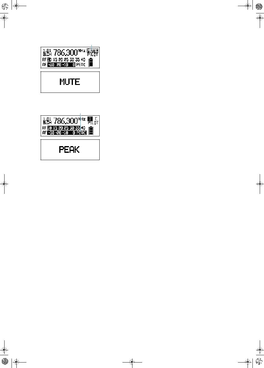
“MUTE” display
The “MUTE” display appears on the display panel and the backlighting of the standard display switches from green to red. In addition, the text “MUTE”
flashes in alternation with the standard display when
y the RF signal of the received transmitter is too weak,
y the received transmitter has been muted (with the pilot tone transmission or evaluation activated).
Modulation display
The level display for audio signal “AF” shows the modulation of the received transmitter.
When the transmitter’s audio input level is excessively high, the receiver’s level display for audio signal “AF” shows full deflection.
When the transmitter is overmodulated frequently or for an extended period of time, the text “PEAK” (backlit in red) flashes in alternation with the standard display.
45

EM_550_G2.book Seite 46 Donnerstag, 27. November 2003 1:33 13
Preparing the receiver for use
Mounting the receiver feet
To ensure that the receiver cannot slip on the surface on which it is placed, four self-adhesive soft rubber feet are supplied.
Ensure that the base of the receiver is clean and free from grease before mounting the rubber feet.
Fix the rubber feet to the base of the receiver by peeling of the safety paper and fitting them as shown in the digram on the left.
Attention!
Some furniture surfaces have been treated with varnish, polish or synthetics which might cause stains when they come into contact with other synthetics. Despite a thorough testing of the synthetics used by us, we cannot rule out the possibility of staining.
|
Connecting the antennas |
|
|
The supplied telescopic antennas can be mounted quickly and easily and are |
|
|
suitable for all applications where – good reception conditions provided – a |
|
|
wireless transmission system is to be used without a large amount of |
|
installation work. |
||
|
Connect the telescopic antennas to the BNC sockets and at the rear of the receiver.
Pull the telescopic antennas out and align them upwards in a V-shape.
Connecting and mounting remote antennas
When the receiver position is not the best antenna position for optimum reception, you can use remote antennas. These are available as accessories.
Connect the remote antennas to the BNC sockets and at the rear of the receiver. For connecting the antennas, use RG 58 co-axial cable. Ready made up antenna cables from Sennheiser are available as accessories with lengths of 1 m, 5 m and 10 m (see “Accessories” on page 69).
Attention!
To supply an active directional antenna (e.g. A 12 AD-UHF for the UHF range) or an antenna booster (e.g. AB 1), a direct voltage (which cannot be switched off) is output via the BNC sockets. If you use antennas from other manufacturers, take into account that these must be installed with direct voltage decoupling, i.e. isolated. The output voltage supply is shortcircuit proof. An active antenna connected to this supply increases the current consumption of the overall unit.
46
EM_550_G2.book Seite 47 Donnerstag, 27. November 2003 1:33 13
Essential notes on mounting remote antennas:
yPosition antennas in the same room in which the transmission takes place!
yMaintain a minimum distance of 50 cm from metal objects (including reinforced-concrete walls)!
yMaintain a minimum distance of 1 m between receiving antennas!


Daisy-chaining up to eight twin receivers
The twin receivers feature an integrated antenna splitter so that up to eight twin receivers can be daisy-chained without any additional antenna splitters being required. Only daisy-chain receivers which operate in the same frequency range (see “The channel bank system” on page 40).
Connect the two supplied telescopic antennas or two remote antennas (optional accessories) to the BNC sockets and at the rear of the first twin receiver.
Use BNC cables to daisy-chain the twin receivers as shown in the diagram on the left.
Note:
To supply an active directional antenna, a direct voltage (which cannot be switched off) is output via the BNC sockets and of the twin receivers. For optimum reception quality, we recommend limiting the number of daisy-chained twin receivers to 8.
|
Connecting the mains cable |
|
Use the mains cable to connect the twin receiver to the mains |
|
(90–264 V AC, 50–60 Hz). |
Pass the mains cable through the cable grip .
Plug the mains cable into socket .
47
 Loading...