


SCC-B5342
SCC-B5343
Digital Color Dome Camera
operating instructions
imagine the possibilities
Thank you for purchasing this Samsung product. To receive more complete service, please register your product at
www.samsung.com/global/register
B-POR JAP SPA FRA ENG
EXPLANATION OF
SAFETY RELATED SYMBOLS
CAUTION |
RISK OF ELECTRIC SHOCK. |
DO NOT OPEN |
CAUTION: TO REDUCE THE RISK OF ELECTRIC SHOCK, |
DO NOT REMOVE COVER (OR BACK) |
NO USER-SERVICEABLE PARTS INSIDE |
REFER SERVICING TO QUALIFIED SERVICE PERSONNEL |
This symbol indicates that dangerous voltage consisting a risk of electric shock is present within this unit.
This symbol indicates that there are important operating and maintenance instructions in the literature accompanying this unit.
WARNING
•To reduce the risk of fire or electric shock, do not expose this appliance to rain or moisture.
•To prevent injury, this apparatus must be securely attached to the floor/wall in
accordance with the installation instructions.
•If this power supply is used at 240V ac, a suitable plug adapter should be used.
WARNING
1.Be sure to use only the standard adapter that is specified in the specification sheet. Using any other adapter could cause fire, electrical shock, or damage to the product.
2.Incorrectly connecting the power supply or replacing battery may cause explosion, fire, electric shock, or damage to the product.
3.Do not connect multiple cameras to a single adapter. Exceeding the capacity may cause abnormal heat generation or fire.
4.Securely plug the power cord into the power receptacle. Insecure connection may cause fire.
5.When installing the camera, fasten it securely and firmly. The fall of camera may cause personal injury.
6.Do not place conductive objects (e.g. screwdrivers, coins, metal parts, etc.) or containers filled with water on top of the camera. Doing so may cause personal injury due to fire, electric shock, or falling objects.
7.Do not install the unit in humid, dusty, or sooty locations. Doing so may cause fire or electric shock.
8.If any unusual smells or smoke come from the unit, stop using the product. In such case, immediately disconnect the power source and contact the service center. Continued use in such a condition may cause fire or electric shock.
9.If this product fails to operate normally, contact the nearest service center. Never disassemble or modify this product
in any way. (SAMSUNG is not liable for problems caused by unauthorized modifications or attempted repair.)
10.When cleaning, do not spray water directly onto parts of the product. Doing so may cause fire or electric shock.

CAUTION
1.Do not drop objects on the product or apply strong blows to it. Keep away from a location subject to excessive vibration or magnetic interference.
2.Do not install in a location subject to high temperature (over 140°F), low temperature (below -49°F), or high
humidity. Doing so may cause fire or electric shock.
3.If you want to relocate the already installed product, be sure to turn off the power and then move or reinstall it.
4.Remove the power plug from the outlet when there is a lighting storm. Neglecting to do so may cause fire or damage to the product.
5.Keep out of direct sunlight and heat radiation sources. It may cause fire.
6.Install it in a place with good ventilation.
7.Avoid aiming the camera directly towards extremely bright objects such as sun, as this may damage the CCD image sensor.
8.Apparatus shall not be exposed to dripping or splashing and no objects filled with liquids, such as vases, shall be placed on the apparatus.
9.The Mains plug is used as a disconnect device and shall stay readily operable at any time.
FCC Statement
This device complies with part 15 of the FCC Rules. Operation is subject to the following two conditions:
1) This device may not cause harmful interference, and
2) This device must accept any interference received including interference that may cause undesired operation.
Caution
This equipment has been tested and found to comply with the limits for a Class A digital device, pursuant to part 15 of FCC Rules. These limits are designed to provide reasonable protection against harmful interference when the equipment is operated in a commercial environment.
This equipment generates, uses, and can radiate radio frequency energy and, if not installed
and used in accordance with the instruction manual, may cause harmful interference to radio communications. Operation of this equipment in a residential area is likely to cause harmful interference in which case the user will be required to correct the interference at his own expense.
IC Compliance Notice
This Class A digital apparatus meets all requirements of the Canadian Interference.-Causing Equipment
Regulations of ICES-003.
ENG

IMPORTANT SAFETY INSTRUCTIONS
1.Read these instructions.
2.Keep these instructions.
3.Heed all warnings.
4.Follow all instructions.
5.Do not use this apparatus near water.
6.Clean only with dry cloth.
7.Do not block any ventilation openings. Install in accordance with the manufacturer’s instructions.
8.Do not install near any heat sources such as radiators, heat registers, or other apparatus (including amplifiers) that produce heat.
9.Do not defeat the safety purpose of the polarized or grounding-type plug. A polarized plug has two blades with one wider than the other. A grounding type plug has two blades and a third grounding prong. The wide blade or the third prong is provided for your safety.
If the provided plug does not fit into your outlet, consult an electrician for replacement of the obsolete outlet.
10.Protect the power cord from being walked on or pinched particularly at plugs, convenience receptacles, and the point where they exit from the apparatus.
11.Only use attachments/accessories specified by the manufacturer.
12.Use only with cart, stand, tripod, bracket, or table specified by the manufacturer, or sold with the apparatus.
13.Unplug this apparatus when a card is used. Use caution when moving the cart/ apparatus combination to avoid injury from tip-over.
14.Refer all servicing to qualified service personnel. Servicing is required when the apparatus has been damaged in any way, such as powersupply cord or plug is damaged, liquid has been spilled or objects have fallen into the apparatus, the apparatus has been exposed to rain or moisture, does not operate normally, or has been dropped.
Apparatus shall not be exposed to dripping or splashing and no objects filled with liquids, such as vases, shall be placed on the apparatus


Contents |
|
Overview....................................................................................... |
6 |
About this guide............................................................................. |
6 |
Product overview........................................................................... |
6 |
Main features.................................................................................. |
6 |
Components................................................................................... |
6 |
Checking components in the package........................................ |
6 |
Components of your camera...................................................... |
7 |
Installation................................................................................... |
8 |
Setting switches............................................................................. |
8 |
Setting function switches............................................................ |
8 |
Connecting cables and changing the settings.......................... |
10 |
Installing camera.......................................................................... |
11 |
Before installation..................................................................... |
11 |
Installation procedure............................................................... |
11 |
Adjusting the camera direction.................................................. |
12 |
Appendix A: Specifications for NTSC Standard............ |
14 |
Appendix B: Specifications for PAL Standard............... |
15 |
ENG

Overview
About this guide
This user guide includes basic instructions for the product. It is recommended that all users read this guide before use.
This guide is divided as follows:
Chapter 1, “Overview,” introduces the user guide and product related information. (This chapter)
Chapter 2, “Installation,” explains how to set and install the product.
Appendix, “Specifications,” provides the specifications of the product.
Product overview
This is the high resolution (540 TV lines) dome camera equipped with a Vari-focal lens, which has no dynamic delay when implementing motion pictures, and provides the features such as digital noise reduction (DNR) by realtime CCD defect compensation, low speed shutter (LSS: Auto x128) to implement clear picture quality, Day/Night color compensation, and the like.
Main features
Power: DC 12V/AC 24V
Special functions
Line lock (LL) control
Auto white balancing
Horizontal/vertical image reversing
Flickerless control
Low shutter speed control
Backlight compensation control
Automatic switching between color and black & white modes
Equipped with vari-focal lens
Auto Iris function
Digital noise reduction (DNR)
 Dynamic CCD defect compensation
Components
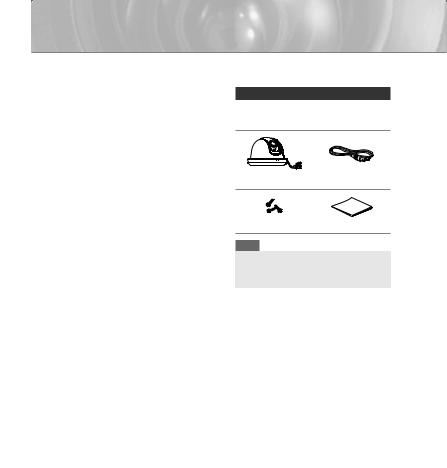
Checking components in the package
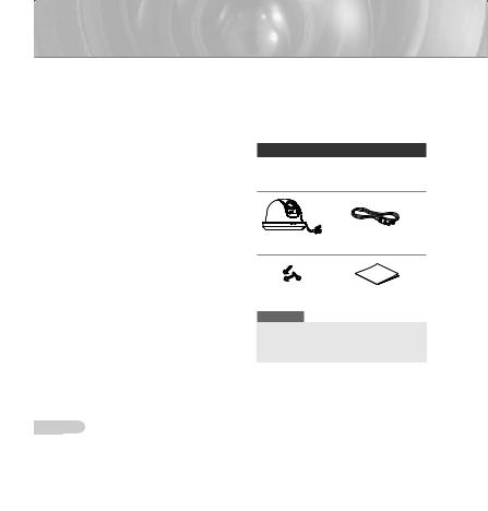
Please check your camera and accessories are included in the package. Those components are as shown below:
Camera |
Test Monitor Cable |
Tab screw |
User’s Guide |
Note
The test monitor cable is used to test the camera by connecting to a portable display. If you really want to connect the camera to a monitoring display, use the BNC cable.
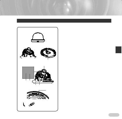
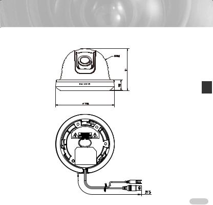
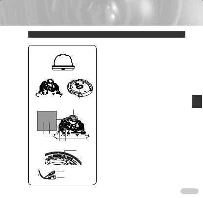
dome: Covers the main body for protection.
1
body: Includes a lens, a switch board, a PCB screws, and such.
bracket: Used as a ceiling or wall fixture. It fixed using three long tab screws provided in the
package.
2 |
3 |
Stopper: If drawing the cable from a hole in |
|
|
ceiling, remove this stopper and pass the cable |
|
|
through the opening to connect. |
|
|
lever: Using this lever, the lens zoom can be |
|
|
adjusted and fixed. |
|
|
lever: The lens focus can be adjusted by |
|
4 |
rotating it left or right. Rotate it clockwise for fixing. |
|
Lens |
fixing screw: Using this screw, the slope of the |
|
can be adjusted and fixed. |
|
|
|
|
|
|
Switch board: Includes two kinds of control switches |
|
|
as function switches and phase-control switches. |
|
|
board has eight function switches in the middle |
|
|
two phase-control buttons on each side of the |
|
|
function switch area. |
5 6 |
|
Installation Guide Mark: This mark must be aligned |
|
|
the marking on the bracket when attaching the |
|
7 8 |
camera to the bracket. |
|
|
releaser: Push it outward and rotate the main |
|
9 |
in UNLOCK direction when you want to remove |
|
|
Mount bracket from the Main body or to remove |
|
0 |
installed camera from the Mount bracket. |
|
|
: Connect the Video connector to BNC cable |
|
|
Power connector to power adapter. |
! Video connector


 Power connector
ENG

Installation
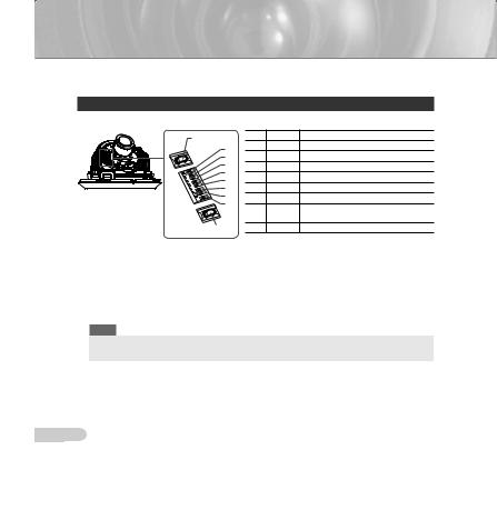
Setting switches
Setting function switches
To set the available functions on your camera, adjust eight switches as shown below:
DEC |
No |
Name |
Brief description |
|
1 |
LL |
Line lock ON/OFF |
||
8 |
||||
2 |
LSS |
Sens-up or Low speed shutter ON/OFF |
||
7 |
||||
6 |
3 |
H-REV |
Horizontal reverse ON/OFF |
|
5 |
4 |
V-REV |
Vertical reverse ON/OFF |
|
4 |
||||
5 |
BLC |
Backlight compensation ON/OFF |
||
3 |
||||
2 |
6 |
FL |
Flickerless ON/OFF |
|
1 |
7 |
D/N |
Automatic switching between color and |
|
|
black & white ON/OFF |
|||
|
|
|
||
INC |
8 |
AWB |
Automatic white balance ON/OFF |
1.Switch 1 (LL): When this switch is set to OFF, the camera operates in the internal synchronization mode, while when it is set to ON, the camera operates in the line lock mode. In the internal synchronization mode, the camera always uses an inside crystal oscillator for synchronization. However if multiple cameras are connected to a sequential switcher, picture rolling or flickering may occur when switching from one camera to another. In this case, you can set this switch to ON to solve this problem.
The line lock mode allows the camera to use the phase of the AC power as the synchronization reference. In this mode, you can use the phase control buttons(INC/DEC).
Note
When you are using the DC 12V power, set this switch to OFF. The line lock feature will not normally operate even when the switch is set to ON.
Set the LL switch to ON while the AC power is connected. If any picture roll happens, you have to adjust the phase using the phase-control buttons. Press the INC or DEC button to increase or decrease the phase by one degree.

2. |
Switch 2 (LSS): This sens-up mode accumulates the image fields in memory to reduce |
|
|
noise but increase the brightness and contrast rate. When this switch is set to ON, the |
|
|
camera automatically switches to a maximum of 128 times of image acquisition speed to |
|
|
implement a clear picture for darker image. |
|
3. |
Switch 3 (H-REV): When this switch is set to ON, the camera image is reversed horizontally. |
|
|
If you want to monitor your site using a mirror, you can use this feature to see the right |
|
|
image. |
|
4. |
Switch 4 (V-REV): When this switch is set to ON, the camera image is reversed vertically. |
|
|
If your camera reluctantly displays the vertically reversed image, you can use this feature to |
|
|
see the right image. |
|
5. |
Switch 5 (BLC): When this switch is set to ON, you can view a clear image even though the |
ENG |
|
camera faces any excessive light such as sunlight and fluorescent light. When it is set to |
|
6. |
OFF, the subject with excessive light is not clearly shown. |
|
Switch 6 (FL): When this switch is set to ON, the shutter speed is fixed to 1/100 sec (for |
|
|
|
NTSC) or 1/120 sec (for PAL) to prevent screen from flickering by the disaccordance |
|
|
between vertical synchronous frequency (50Hz for NTSC, 60Hz for PAL) and on-and-off |
|
|
frequency of a light. |
|
7. |
Switch 7 (D/N): When this switch is set to ON, the camera automatically switches between |
|
|
color and B&W according to the brightness of the vicinity. |
|
8. |
Switch 8 (AWB): This switch adjusts white balancing. When this switch is set to ON, this |
|
|
camera operates in ATW mode, and in case of OFF, this camera operates in AWC mode. |
|
ATW (Auto Tracking White Balance): The color temperature is automatically adjusted according to the environmental change. (Approx. 2000°K to 11,000°K)
AWC (Auto White Balance Control): It stores the color temperature just when the switch is changed to
OFF. Accordingly color temperatures are adjusted by the stored value.
Caution
-. The IRIS setting range for the camera is approximately 80 to 120 IRE. It means the camera does not provide the IRIS full open/close feature but the restricted variation range.
-. Use the camera after setting to the proper level (80 IRE or above) because the IRIS hunting may occur when the level is 75 IRE or below.

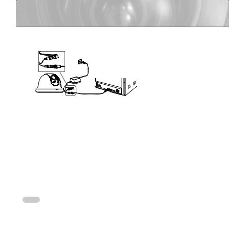
Connecting cables and changing the settings
Before installing your camera, you have to adjust the lens focus, zoom, and switch settings.
Monitor
 BNC Cable
To connect cables
1.Connect the BNC cable to the Video connector attached on your camera.
2.Connect the BNC cable to the Video Input on a monitor.
3.Connect the power adapter to the Power connector attached on your camera. When the monitor is turned on, the camera image appears.
To adjust the lens focus, zoom, and function settings
1.Remove the Cover dome and Inner cover. For more details about the removing procedures, see “Installation procedure,” in the Installing camera section on the next page.
2.Adjust the focus, zoom, and function settings of your camera using the Focus lever, Zoom lever, and Switch board while you are viewing the image on the screen.
3.If you want to fix the adjusted focus and zoom, screw up the levers.
 10
10
Installing camera
Before installation
Before installing your camera, you have to read the following cautions:
You have to check whether the location (ceiling or wall) can bear five times the weight of your camera. |
||
Don’t let the cable to be caught in improper place or the electric line cover to be damaged. Otherwise it |
||
|
may cause a breakdown or fire. |
|
When installing your camera, don’t allow any person to approach the installation site. If you have any |
||
|
valuable things under the place, move them away. |
|
Partial blind spot can occur at tilt angles of less than 20°, depending on the lens configuration. |
||
|
ENG |
|
1 |
install your camera |
|
up the outer casing with a flat-head screwdriver |
||
|
||
|
remove the protective cover from the Main body of |
|
|
camera. |
|
|
Remove the Mount bracket from the Main body by |
|
|
rotating the Main body in the UNLOCK direction while |
|
2 |
pushing the Lock releaser outward. If it is not easily |
|
done, rotate the Mount bracket in the LOCK direction |
||
|
while holding small holes on the Mount bracket. |
|
the Mount bracket to the location (ceiling or wall) with supplied three screws.
3 


 Ceiling mount


 opener
Note
The CAMERA FRONT sign on the Mount bracket should face the camera monitoring area.
11 
4If a hole has been drilled on the bracket installation surface for cable access, press down to remove the Cable Stopper and then draw the cable in. If connecting through the side of the camera, use the empty space opposite to the side marked CAMERA FRONT.
5Now attach the Main body to the Mount bracket by rotating it in the LOCK direction after aligning the Groove mark on the Main body with the wide groove around the CAMERA FRONT inlay.
6Adjust the camera direction. For more details on the direction control, see “Adjusting the camera direction,” on the same page. When required to adjust the zoom and focus for your camera, see “Connecting cables and changing the settings,” on page 10.
7Attach the Inner cover to the Main body by pressing it until a “click” sound is heard after aligning two screw holes on the Wing lockers of the Inner cover with two screw holes on the Main body’s left and right sides.
8Finally attach the Cover dome to the Main body by pressing it until a “click” sound is heard after aligning the bump inside the Cover dome with the Groove mark on the Main body.
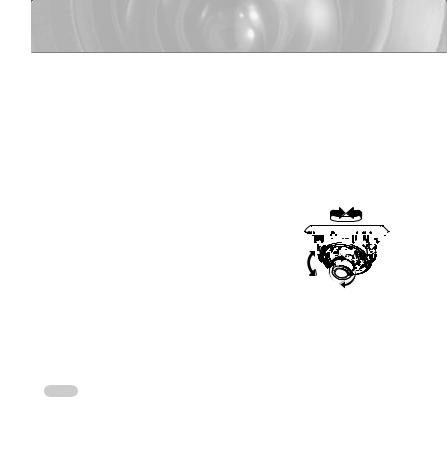
Adjusting the camera direction
When the camera is fixed on the ceiling, you can adjust the camera viewing angle. You can rotate your camera
leftward or rightward (Panning), and can change the slope of your camera upward or downward (Tilting).
In case of panning, the rotation limit of your camera is  set to 355 degree (100 degree clockwise and 255 degree


 counterclockwise). The rotation is stopped by the Stopper


 inside of the camera. For panning control, first unfasten Tilting


 two screws located on the bottom and rotate in the


 direction you want, and then fasten them to fix the camera.
Tilt can be adjusted between 0° to 90°; however, tilt angles of less than 20° may result in a partial blind spot, depending on your lens configuration. To fix the location after adjusting the tilting angle, use the Tilt fixing screws.
To adjust the focus and zoom of your camera, use the Zoom lever and Focus lever. When you install the camera on the inclined ceiling or wall, you can rotate the camera lens to see a correct direction image.
 12
12
SCC-B5342/B5343
ENG
13 

Appendix A: Specifications for NTSC Standard
Item |
|
|
|
|
|
Details |
|
|
Product type |
CCTV color dome camera |
|
|
|
||||
Power input |
AC 24V ± 10% (60Hz ± 0.3 Hz), DC 12V +10%/-5% |
|
||||||
Broadcast type |
NTSC Standard System (525 Lines, 60 Fields) |
|
||||||
Power consumption |
Approx. 1.7W |
|
|
|
|
|
||
Image device |
1/3 inch IT Type Super-HAD CCD |
|
|
|
||||
Pixels |
Total: 811(H) x 508(V), 410,000 pixels |
|
||||||
Effective: 768(H) x 494(V), 380,000 pixels |
|
|||||||
|
|
|||||||
Scanning mode |
525 Lines, 2:1 Interlace |
|
|
|
|
|
||
Scanning line frequency |
Horizontal: 15.734Hz(INT)/15.750Hz(LL) |
|
||||||
Vertical: 59.94Hz(INT)/60Hz(LL) |
|
|
|
|||||
|
|
|
|
|||||
Synchronization mode |
INT/Line Lock (Adjusting the phase using INC/DEC button) |
|
||||||
Horizontal resolution |
540 TV Lines |
|
|
|
|
|
||
S/N Ratio |
Approx. 50dB |
|
|
|
|
|
||
|
|
|
|
|
|
SCC-B5343 (Color/BW) |
|
SCC-B5342 (Color/BW) |
|
|
Sens-up Off |
|
50IRE |
|
0.4/0.04Lux |
|
0.4/0.4Lux |
Min. object illumination |
|
|
30IRE |
|
0.24/0.024Lux |
|
0.24/0.24Lux |
|
F1.2 |
|
|
15IRE |
|
0.12/0.012Lux |
|
0.12/0.12Lux |
|
|
Sens-up x128 |
|
50IRE |
|
0.0031/0.00031Lux |
|
0.0031/0.0031Lux |
|
|
|
|
|
|
||||
|
|
|
30IRE |
|
0.0019/0.00019Lux |
|
0.0019/0.0019Lux |
|
|
|
|
|
15IRE |
|
0.0009/0.00009Lux |
|
0.0009/0.0009Lux |
Signal output |
COMPOSITE Video(1.0 Vp-p, 75ohm, BNC), Test Monitor OUT(1.0 Vp-p, 75ohm, Harness cable) |
|||||||
Lens |
Auto Iris (DC) / Focal length: 2.5 to 6.0mm / Aperture ratio: 1.2 |
|
||||||
PAN function |
Range: 0 to 355° (100 degree clockwise and 255 degree counterclockwise) |
|||||||
TILT function |
Range: 0 to 90° |
|
|
|
|
|
||
|
Line Lock (LL) |
|
|
|
|
|
||
|
Sens-Up; Low Speed Shutter(LSS) |
|
|
|
||||
|
Horizontal Reverse (H-REV) |
|
|
|
||||
|
Vertical Reverse (V-REV) |
|
|
|
|
|
||
Controls |
Backlight compensation (BLC) |
|
|
|
||||
Flickerless (FL) |
|
|
|
|
|
|||
|
Switching between color and B&W modes (D/N) |
|
||||||
|
Auto white balancing (AWB) |
|
|
|
||||
|
Digital noise reduction (DNR) |
|
|
|
||||
|
Dynamic CCD defect compensation |
|
||||||
Product color |
SCC-B5342N/B5343N : White |
|
|
|
||||
Operation temperature |
-10°C to +50°C |
|
|
|
|
|
||
Operation humidity |
Up to 90% |
|
|
|
|
|
||
Size |
128(Ø) x 91(H)mm |
|
|
|
|
|
||
Weight |
327g |
|
|
|
|
|
||
 14
14

Appendix B: Specifications for PAL Standard
Item |
|
|
|
|
|
Details |
|
|
Product type |
CCTV color dome camera |
|
|
|
||||
Power input |
AC 24V ± 10% (50Hz ± 0.3 Hz), DC 12V +10%/-5% |
|
||||||
Broadcast type |
PAL Standard System (625 Lines, 50 Fields) |
|
||||||
Power consumption |
Approx. 1.7W |
|
|
|
|
|
||
Image device |
1/3 inch IT Type Super-HAD CCD |
|
|
|
||||
Pixels |
Total: 795(H) x 596(V), 470,000 pixels |
|
||||||
Effective: 752(H) x 582(V), 440,000 pixels |
|
|||||||
|
|
|||||||
Scanning mode |
625 Lines, 2:1 Interlace |
|
|
|
|
|
||
Scanning line frequency |
Horizontal: 15.625Hz(INT)/15.625Hz(LL) |
|
||||||
Vertical: 50Hz(INT)/50Hz(LL) |
|
|
|
|||||
|
|
|
|
|||||
Synchronization mode |
INT/Line Lock (Adjusting the phase using INC/DEC button) |
|
||||||
Horizontal resolution |
540 TV Lines |
|
|
|
|
|
||
S/N Ratio |
Approx. 50dB |
|
|
|
|
|
||
|
|
|
|
|
|
SCC-B5343 (Color/BW) |
|
SCC-B5342 (Color/BW) |
|
|
Sens-up Off |
|
50IRE |
|
0.4/0.04Lux |
|
0.4/0.4Lux |
Min. object illumination |
|
|
30IRE |
|
0.24/0.024Lux |
|
0.24/0.24Lux |
|
F1.2 |
|
|
15IRE |
|
0.12/0.012Lux |
|
0.12/0.12Lux |
|
|
Sens-up x128 |
|
50IRE |
|
0.0031/0.00031Lux |
|
0.0031/0.0031Lux |
|
|
|
|
|
|
||||
|
|
|
30IRE |
|
0.0019/0.00019Lux |
|
0.0019/0.0019Lux |
|
|
|
|
|
15IRE |
|
0.0009/0.00009Lux |
|
0.0009/0.0009Lux |
Signal output |
COMPOSITE Video(1.0 Vp-p, 75ohm, BNC), Test Monitor OUT(1.0 Vp-p, 75ohm, Harness cable) |
|||||||
Lens |
Auto Iris (DC) / Focal length: 2.5 to 6.0mm / Aperture ratio: 1.2 |
|
||||||
PAN function |
Range: 0 to 355° (100 degree clockwise and 255 degree counterclockwise) |
|||||||
TILT function |
Range: 0 to 90° |
|
|
|
|
|
||
|
Line Lock (LL) |
|
|
|
|
|
||
|
Sens-Up; Low Speed Shutter(LSS) |
|
|
|
||||
|
Horizontal Reverse (H-REV) |
|
|
|
||||
|
Vertical Reverse (V-REV) |
|
|
|
|
|
||
Controls |
Backlight compensation (BLC) |
|
|
|
||||
Flickerless (FL) |
|
|
|
|
|
|||
|
Switching between color and B&W modes (D/N) |
|
||||||
|
Auto white balancing (AWB) |
|
|
|
||||
|
Digital noise reduction (DNR) |
|
|
|
||||
|
Dynamic CCD defect compensation |
|
||||||
Product color |
SCC-B5342P/B5343P : White |
|
|
|
||||
Operation temperature |
-10°C to +50°C |
|
|
|
|
|
||
Operation humidity |
Up to 90% |
|
|
|
|
|
||
Size |
128(Ø) x 91(H)mm |
|
|
|
|
|
||
Weight |
327g |
|
|
|
|
|
||
ENG
15 

Memo

SCC-B5342
SCC-B5343
Caméra Dôme Couleur Numérique
Mode d’emploi
FRA
imaginez toutes les possibilités
Merci d’avoir acheté ce produit Samsung. Pour obtenir notre service complet, veuillez
enregistrer le produit sur le portail desélectionnez Enregistrement de produit
http://www.samsung.com/cp/et
MESURES DE SÉCURITÉ
AVERTISSEMENT |
RISQUE DE ECHOC ELECTRIQUE NE PAS OUVRIR |
ATTENTION : POUR REDUIRE LES RISQUES DE CHOCS ELECTRIQUES, |
NE RETIREZ PAS LE COUVERCLE (OU LA PARTIE ARRIERE) LES PIECES |
INTERIEURES NE SONT PAS ACCESSIBLES A L’UTILISATEUR. FAITES |
APPEL AU PERSONNEL DE MAINTENANCE QUALIFIE. |
Ce symbole indique la présence, dans cette unité, d’une tension élevée et avise des risques de décharge électrique existants.
Ce symbole indique la présence, dans cette unité, d’une tension élevée et avise des risques de décharge électrique existants.
AVERTISSEMENT
•Afin de réduire le risque d’incendie ou de décharge électrique, n’exposez pas cet appareil à lapluie ni à l’humidité.
•Afin d’éviter les blessures personnelles, fixez fermement l’appareil au sol/à la paroi conformément aux instructions d’installation.
•Si vous utilisez une alimentation électrique
à 240V ca, utilisez un adaptateur de fiche approprié.
AVERTISSEMENT
1.Utiliser uniquement l’adaptateur standard spécifié dans la fiche technique.
L’utilisation de tout autre adaptateur peu causer un incendie, un choc électrique ou endommager le produit.
2.La connexion incorrecte de la source d’alimentation ou le remplacement incorrect de la batterie peut provoquer une explosion, un incendie, un choc électrique ou endommager le produit.
3.Ne pas brancher plus d’une caméra à un adaptateur. Dépasser la capacité peut générer une chaleur anormale ou un incendie.
4.Brancher le cordon d’alimentation sécuritairement à la prise secteur. Une mauvaise connexion peu provoquer un incendie.
5.Lors de l’installation de la caméra, la fixer solidement et sécuritairement. La chute d’une caméra peut causer des blessures corporelles.
6.Ne pas placer d’objets conducteurs (comme des tournevis, pièces de monnaie, objets métalliques, etc.) ou de contenant remplis d’eau sur la caméra. Cela peut causer des blessures corporelles provoquer par un incendie, un choc électrique ou la chute d’ objets.
7.Ne pas installer l’appareil dans un endroit humide, poussiéreux ou plein de suie. Cela peut causer un incendie ou un choc électrique.
8.Si des odeurs ou des fumées inhabituelles s’échappent de l’appareil, arrêter d’utiliser l’appareil. Dans un tel cas, débrancher immédiatement le cordon d’alimentation et contacter le centre de service. Un usage continu dans de telles conditions peut causer un incendie ou un choc électrique.

9.Si l’appareil ne fonctionne pas normalement, contacter le centre de service le plus proche. Ne jamais démonter ou modifier
de quelle que façon que ce soit ce produit.
(SAMSUNG n’est pas responsable des anomalies provoquées par des modifications ou tentatives de réparation non autorisées.)
10.Lors du nettoyage, ne pas vaporiser d’eau directement sur les composants du
produit. Cela peut causer un incendie ou un choc électrique.
AVERTISSEMENT
1.Ne pas laissez tomber d’objet sur le produit ou le soumettre à de violents chocs. Ne pas placer le produit dans un endroit où
il pourrait subir de forte vibration ou des interférences magnétiques.
2.Ne pas installer la caméra dans un endroit où la température pourrait dépasser plus de 50°C, ou être inférieure à 10°C, ou à une humidité élevée. Cela peut causer un incendie ou un choc électrique.
3.Si vous désirez déplacer le produit déjà installé, coupez l’alimentation puis déplacez ou réinstallez le produit.
4.En cas d’orage, retirer la fiche de la prise
électrique. Le non-respect de cette consigne peut provoquer un incendie ou endommager le produit.
5.Placer le produit dans un endroit protégé des rayons du soleil et des sources de chaleur. Cela peut provoquer un incendie.
6.Installer dans un endroit bien ventilé.
7.Éviter de diriger la caméra en direction d’objets extrêmement brillants, tel que le soleil, pour ne pas endommager le capteur d’ image CCD.
8.Veillez à éviter toute projection sur l’appareil et ne placez jamais de récipients contenant un liquide (ex. : vase) dessus.
9.La prise d’alimentation fait office de système de déconnexion ; elle doit donc rester disponible en permanence.
Déclaration relative à la Commission fédérale des communications (FCC)
Cet appareil est conforme à la partie 15 des règlements de la FCC. Le fonctionnement est assujetti aux deux conditions suivantes :
1)Cet appareil ne doit pas produire d’interférence nuisible, et
2)Cet appareil doit accepter toute interférence reçue, dont les interférences pouvant causer un fonctionnement indésirable.
Remarque
Cet appareil a été testé et trouvé conforme aux limites d’un appareil numérique de classe A, en vertu de la partie 15 des règlements de la
FCC. Ces limites sont conçues pour fournir une protection raisonnable contre les interférences nuisibles lorsque l’appareil est utilisé dans
un environnement commercial. Cet appareil génère, utilise et peut rayonner une énergie radiofréquence. S’il n’est pas installer ou utiliser conformément au manuel d’instructions, il peut provoquer des interférences nuisibles aux radiocommunications. Le fonctionnement de cet appareil dans une zone résidentielle est susceptible de provoquer des interférences nuisibles, au quel cas l’utilisateur devra y remédier à ses frais.
Notification de conformité d’IC
Cet appareil numérique de classe A respecte toutes les exigences du Réglement ICES-003 sur les équipements produisant des interférences au Canada.
FRA

INSTRUCTIONS IMPORTANTES RELATIVES À LA SÉCURITÉ
1.Prendre connaissance de ces consignes.
2.Conserver ces consignes.
3.Tenir compte de tous les avertissements.
4.Suivre toutes les consignes.
5.Ne pas utiliser cet appareil à proximité de l’eau.
6.Nettoyer seulement avec un tissu sec.
7.Ne pas boucher les ouvertures de ventilation. Installer conformément aux directives du fabricant.
8.Ne pas installer proche d’une source de chaleur tel qu’un radiateur, d’une bouche d’air chaud et d’autres appareils (comme un amplificateur) qui produisent de la chaleur.
9.Ne pas supprimer le dispositif de sécurité de la fiche polarisée ou avec mise à la terre. Une fiche polarisée est composée de deux lames dont l’une est plus large que l’autre. Une fiche avec mise à la terre est composée de deux lames et d’une broche de mise à la terre. La lame la plus large ou la broche sont prévues pour votre sécurité.
Si la fiche fournie ne convient pas à votre prise secteur, consulter un électricien pour la remplacer.
10.Protéger le cordon d’alimentation pour éviter qu’il ne soit piétiné ou pincé, particulièrement aux fiches, aux prises utilitaires et aux points de sortie des appareils.
11.Utiliser seulement les accessoires/fixations spécifiés par le fabricant.
12.Utiliser seulement avec le chariot, le statif, le trépied, le support ou la plate-forme spécifiés par le fabricant ou vendu avec l’ appareil.
13.Débrancher cet appareil. Lorsqu’un chariot est utilisé, pour éviter des blessures dû au renversement, soyez prudent lors des déplacement de l’ensemble chariot/ appareil.
14.Pour toute opération d’entretien, se référer à du personnel qualifié. Un entretien est nécessaire lorsque l’appareil à subit des dommages tel que : dommages à la fiche ou au cordon d’alimentation, renversement de liquide ou chute d’objet sur l’appareil, exposition de l’appareil à la pluie ou à l’humidité, fonctionnement anormal de l’appareil ou chute de l’appareil.
L’appareil ne doit pas être exposé à la pluie ou aux éclaboussures, et aucun objet rempli de liquide, comme un vase, ne doit être posé sur lui.

Contenu |
|
Aperçu........................................................................................... |
6 |
À propos de ce guide..................................................................... |
6 |
Aperçu du produit.......................................................................... |
6 |
Caractéristiques principales......................................................... |
6 |
Composants................................................................................... |
6 |
Vérification des composants de l’emballage............................... |
6 |
Composants de votre caméra..................................................... |
7 |
Installation................................................................................... |
8 |
Réglage des commutateurs.......................................................... |
8 |
Réglage des commutateurs de fonction..................................... |
8 |
Branchement des câbles et changement des réglage............. |
10 |
Installation de la caméra............................................................. |
11 |
Avant l’installation..................................................................... |
11 |
Méthode d’installation............................................................... |
11 |
Réglage de la direction de la caméra......................................... |
12 |
Annexe A : Caractéristiques pour la norme NTSC...... |
14 |
Annexe B : Caractéristiques pour la norme PAL.......... |
15 |
FRA

Aperçu
À propos de ce guide
Ce guide de l’utilisateur comprend les consignes de base pour l’utilisation de ce produit. Il est recommandé que tout les utilisateurs lisent ce guide avant l’utilisation.
Ce guide est divisé comme suit :
Le chapitre 1, Aperçu, présente le guide de l’utilisateur et les renseignements relatifs au produit. (Ce chapitre)
Le chapitre 2, Installation, décrit le réglage et l’installation de ce produit.
Annexe, Caractéristiques, indique les caractéristiques du produit.
Équiper d’un objectif à focale variable
Fonction d’iris automatique
Réduction du bruit numérique (RBN)
Compensation dynamique de défaut du capteur CCD
Composants
Vérificationdescomposantsdel’emballage
Vérifier que la caméra et les accessoires se trouvent dans l’emballage. Ces composants sont indiqués ci-dessous :
Aperçu du produit
Voici la caméra dôme à haute résolution
équipée d’un objectif à focale fixe, sans retard dynamique lors de prises de vue et présentant des caractéristiques, comme la réduction
du bruit numérique par compensation de défaut du capteur CCD en temps réel et un obturateur à basse vitesse (OBS : Auto x128) pour la prise d’images claires de qualité, la compensation des couleurs de jour/nuit, etc.
Caractéristiques principales
Alimentation : 12 V c.c./24 V c.a.
Fonctions spéciales
Commande de verrouillage de ligne (VL)
Balance automatique des blancs
Inversion d’image horizontale/verticale
Commande sans oscillation (SOSC)
Commande de vitesse de l’obturateur à basse vitesse
Commande de compensation de contre-jour
Commutation automatique entre les modes couleur et noir et blanc
Caméra Câble de l’écran de contrôle
Vis de montage |
Guide de l’utilisateur |
Remarque
Le câble de l’écran de contrôle est utilisé pour contrôler la caméra en branchant un écran portatif.
Utiliser le câble de type BNC pour brancher la caméra à un écran de surveillance.
suivants :
1
2 3
4
Objectif
5 6 

 7 8
7 8
9
0
Couvercle en forme de dôme : Protège le corps principal.
principal : Il comprend un objectif, un panneau de commande, un circuit imprimé, des vis, etc.
Support de montage : Il est utilisé pour fixation au plafond au mur. Il est fixé à l’aide de trois longues vis de montage
dans l’emballage.
Stoppeur de câble : si vous tirez le câble à partir d’un trou dans le plafond, enlevez ce stoppeur et passez le
par l’ouverture pour le brancher.
de zoom : Utiliser ce levier pour régler le zoom de et le fixer.
de mise au point : La mise au point de l’objectif s’effectue en faisant pivoter le levier à gauche ou à droite.
fixer.le levier dans le sens d’une aiguille d’une montre pour de fixation de l’inclinaison : À l’aide de cette vis, l’angle
d’inclinaison de l’objectif peut être ajusté et fixé.
Panneau de commande : Il comprend deux types de commutateurs de commande : des commutateurs de fonction
des commutateurs de commande de phase. Le panneau comporte huit commutateurs de fonctions au centre et deux commutateurs de réglage de phase de chaque côté de la zone
commutateurs de fonction.
du guide d’installation : cette marque doit être avec le marquage du support lors de l’installation de la au support.
Dispositif de déverrouillage : Le déplacer vers l’extérieur faire pivoter le corps principal pour le DÉVERROUILLAGE
vous désirez retirer le support de montage du corps principal ou pour retirer la caméra installée précédemment du
de montage.
: Brancher le connecteur vidéo au câble BNC et le connecteur d’alimentation à l’adaptateur d’alimentation.
! |
Connecteur vidéo |
|
Connecteur |
|
d’alimentation |
FRA


Installation
Réglage des commutateurs
Réglage des commutateurs de fonction
Pour régler les fonctions disponibles de votre caméra, régler les huit commutateurs comme suit :
DEC |
No. |
Nom |
Courte description |
|
1 |
VL |
Marche/Arrêt (ON/OFF) du verrouillage de |
||
8 |
ligne |
|||
2 |
OBV |
|||
7 |
Marche/Arrêt (ON/OFF) du mode Sens-up ou |
|||
6 |
|
|
obturateur basse vitesse |
|
3 |
RENV-H |
Marche/Arrêt (ON/OFF) de l’inversion |
||
5 |
||||
horizontale |
||||
4 |
4 |
RENV-V |
Marche/Arrêt (ON/OFF) de l’inversion |
|
3 |
verticale |
|||
2 |
5 |
CCJ |
Marche/Arrêt (ON/OFF) de la compensation |
|
1 |
du contre-jour |
|||
|
|
|||
|
6 |
SOSC |
Marche/Arrêt (ON/OFF) de la commande |
|
|
sans oscillation |
|||
INC |
|
|
||
7 |
J/N |
Marche/Arrêt (ON/OFF) de la commutation |
||
|
automatique entre les modes couleur et noir |
|||
|
|
|
et blanc |
|
|
8 |
BAB |
Marche/Arrêt (ON/OFF) de la balance |
|
|
automatique des blancs |
|||
|
|
|
1.Commutateur 1 (VL) : Lorsque ce commutateur est en position Arrêt (OFF), la caméra fonctionne en mode de synchronisation interne alors que lorsque le commutateur est en position Marche (ON), la caméra fonctionne en mode de verrouillage sur la tension d’alimentation.
En mode de synchronisation interne, la caméra utilise toujours un oscillateur à cristal interne pour la synchronisation. Cependant, si plusieurs caméras sont branchées à un commutateur séquentiel, un roulement ou une oscillation de l’image peut se produire lors de la commutation d’une caméra à l’autre. Dans ce cas, régler le commutateur à la position Marche (ON) pour remédier à ce problème.
Le mode de verrouillage de ligne permet à la caméra d’utiliser la phase de la tension d’alimentation c.a. comme référence de synchronisation. Dans ce mode, il est possible d’utiliser les boutons de commande de phase (RED/AUG).
Remarque
Lors de l’utilisation de la tension d’alimentation 12 V c.c., régler ce commutateur à Arrêt (OFF). La fonction de verrouillage de ligne ne fonctionne pas normalement même si le commutateur est en position Marche (ON).
 Loading...