


Ultra High Resolution Camera SCB-2000 User Guide
Before installing and operating this product, please read this manual thoroughly.
ENGLISH

Thank you for purchasing a SAMSUNG CCD CAMERA.
Before operating the camera, confirm the camera model and correct input power voltage. In order to that you can understand this manual thoroughly, we will explain the model pert numbers.
ν SCB-2000 SERIES |
|
• NTSC MODEL |
• PAL MODEL |
SCB-2000N |
SCB-2000P |
SCB-2000ND |
SCB-2000PD |
|
SCB-2000PH |
ν MODEL DESCRIPTION
• SCB-2000XX
__
 POWER SOURCE SIGNAL SYSTEM
•SIGNAL SYSTEM N → NTSC MODEL P → PAL MODEL
•POWER SOURCE
→AC 24V / DC 12V D → DC 12V
H → AC 230V
The lightning flash with an arrowhead symbol, within an equilateral triangle is intended to alert the user to the presence of uninsulated “dangerous voltage” within the product's enclosure that may be of sufficient magnitude to constitute a risk of electric shock to persons.
The exclamation point within an equilateral triangle is intended to alert the user to the presence of important operating and maintenance (servicing) instructions in the literature accompanying the appliance.
INFORMATION-This equipment has been tested and found to comply with limits for a Class A digital device, pursuant to part 15 of the FCC Rules. These limits are designed to provide reasonable protection against harmful interference when the equipment is operated in a commercial environment. This equipment generates, uses, and can radiate radio frequency energy and, if not installed and used in accordance with the instruction manual, may cause harmful interference to radio communications.
Operation of this equipment in a residential area is likely to cause harmful interference in which case the user will be required to correct the interference at his own expense.
WARNING : Changes or modifications not expressly approved by the manufacturer could void the user’s authority to operate the equipment.
WARNING : To prevent electric shock and risk of fire hazards:
Do NOT use power sources other than that specified.
Do NOT expose this appliance to rain or moisture.
This installation should be made by a qualified service person and should conform to all local codes.

Contents
•Features…………………………………………………………………………… 5
•Warnings & Cautions… ……………………………………………………… 6
•Precautions… …………………………………………………………………… 7
•Components and Accessories……………………………………………… 8
•Overview………………………………………………………………………… 9
•Installation… …………………………………………………………………… 10
■LENS………………………………………………………………………………………… 10…
■Connecting to the Monitor… ………………………………………………………… 12…
■Using Coaxial Communications……………………………………………………… 13…
■Connecting to the Power……………………………………………………………… 14
•Operating your Camera……………………………………………………… 15
■Menu Configuration…………………………………………………………………… 15…
■Menu Setup… …………………………………………………………………………… |
15… |
•LENS……………………………………………………………………………………… |
16… |
•EXPOSURE……………………………………………………………………………… |
17… |
•WHITE BALANCE… …………………………………………………………………… |
19… |
•SSDR……………………………………………………………………………………… 20…
•BACKLIGHT……………………………………………………………………………… 20…
•SSNR3…………………………………………………………………………………… 22…
•DAY/NIGHT……………………………………………………………………………… 23…
•SPECIAL… ……………………………………………………………………………… 24…
•EXIT… …………………………………………………………………………………… 28
• Troubleshooting………………………………………………………………… 29
• Specifications…………………………………………………………………… 30 

Features
High Resolution
By adopting a diagonal 6mm(1/3") 410,000 (NTSC) pixel, 470,000(PAL) pixel SONY CCD, the camera produces clear picture quality with a horizontal resolution of 600 TV lines for color.
Excellent Sensitivity
 SSDR
SSDR
 (Samsung Super Dynamic Range)
For images with high contrast between bright and dark areas from difficult lighting conditions such as backlighting, this camera selectively illuminates darker areas while retaining the same light level for brighter areas to even out the overall brightness.
DIS (Digital Image Stabilizer)
The built-in high sensitivity COLOR CCD produces a clear image even in
0.05Lux(COLOR), 0.0001Lux(SENS-UP) or lower illumination.

 SSNR3 (Samsung Super Noise
  Reduction) Function
The high-performance W-V DSP chip effectively removes low-light gain noise and afterimage to provide clear images even in dark environments.
Electrical Day&Night
The DIS function compensates for any camera movement, to produce more stable pictures.
Video/DC Drive Lens Support
You can select Video or DC Drive Lens from the menu.
Communication
Coaxial communication methods are supported.
- Protocol : Pelco Coaxitron
Miscellaneous Functions
The camera automatically identifies when it is |
HLC(High Light Compensation), SENS-UP, FLIP |
|
either day or night time and switched |
||
accordingly. During daylight the camera will |
(H/V-REV), D-ZOOM, SHARPNESS, MOTION |
|
switch to color to obtain excellent image |
DETECTION and PRIVACY functions are provided. |
|
clarity, while at night the camera will switch to |
|
|
monochrome to obtain improved picture |
OSD |
|
definition. |
|
|
|
The camera’s OSD is complimented by 18 |
|
Motion Detection |
languages. |
|
- NTSC : Korean, English, French, Spanish, |
||
|
Japanese, Portuguese,Taiwanese |
|
Since the camera detects motion without any |
- PAL : English, French, German, Spanish, |
|
Italian, Chinese, Russian, Czech, |
||
additional external sensor, you can monitor |
||
Polish, Romanian, Serbian, Swedish, |
||
activity more efficient. |
||
Danish,Turkish, Portuguese |
||
|
COLOR CCD CAMERA 4 User Guide |
COLOR CCD CAMERA 5 User Guide |

Samsung Techwin cares for the environment at all product manufacturing stages to preserve the environment, and is taking a number of steps to provide customers with more environment-friendly products.The Eco mark represents Samsung Techwin’s will to create environment-friendly products, and indicates that the product satisfies the EU RoHS Directive.
Warnings & Cautions
This information is provided to ensure your safety and to prevent any losses, financial or otherwise. Please read it carefully and use the product accordingly.
*For product inquiries,please contact the retail shop where you bought the camera.The use of equipment such as anaerialladderwhileprovidingafter-salesserviceshallbeatyourexpense.
*Separatethepowerplugduringathunderstorm.
*This product is only part of a surveillance system. Therefore, we can't compensate for material loss and personal injuries by robbery, fire, natural disaster or something like this type.
 Warning/Attention/Special Mark Messages
|
|
|
|
|
Ignoring this information may result in |
|
|
Ignoring this information may result in |
||||||||||||||
|
|
|
|
|
material loss and serious personal |
|
|
|
|
|||||||||||||
|
|
|
|
|
|
|
material loss and a slight injuries. |
|||||||||||||||
|
|
|
|
|
injuries including death. |
|
|
|
|
|||||||||||||
|
|
|
|
|
|
|
|
|
|
|
|
|
||||||||||
|
|
|
|
|
Indicates“NeverAllowed.” |
|
|
Indicates“No Disassembling.” |
||||||||||||||
|
|
|
|
|
|
|
|
|
|
|
|
|
|
|
|
|
|
|
|
|
|
|
|
|
|
|
|
|
|
|
|
|
|
|
|
|
|
|
|
|
|
|
|
|
|
|
|
|
|
|
|
|
|
|
|
|
|
|
|
|
|
|
|
|
|
|
|
|
|
|
|
|
|
|
|
|
|
|
|
|
|
|
|
|
|
|
|
|
|
|
|
|
|
|
|
|
|
|
|
|
|
|
|
|
|
|
|
|
|
|
|
|
|
|
|
|
|
|
|
|
|
|
|
|
|
|
|
|
|
|
|
|
|
|
|
|
|
|
|
|
|
|
|
|
|
|
|
|
|
|
|
|
|
|
|
|
|
|
|
|
|
|
|
|
|
|
|
|
|
|
|
|
|
|
|
|
|
|
|
|
|
|
|
|
|
|
|
|
|
|
|
|
|
|
|
|
|
|
|
|
|
|
|
|
|
|
|
|
|
|
|
|
|
|
|
|
|
|
|
|
|
|
|
|
|
|
|
|
|
|
|
|
|
|
|
|
|
|
|
|
|
|
|
|
|
|
|
|
|
|
|
|
|
|
|
|
|
|
|
|
|
|
|
|
|
|
|
|
|
|
|
|
|
|
|
|
|
|
|
|
|
|
|
|
|
|
|
|
|
|
|
|
|
|
|
|
|
|
|
|
|
|
|
|
|
|
|
|
|
|
|
|
|
|
|
|
|
|
|
|
|
|
|
|
|
|
|
|
|
|
|
|
|
|
|
|
|
|
|
|
|
|
|
|
|
|
|
|
|
|
|
|
|
|
|
|
|
|
|
|
|
|
|
|
|
|
|
|
|
|
|
|
|
|
|
|
|
|
|
|
|
|
|
|
|
|
|
|
|
|
|
|
|
|
|
|
|
|
|
|
|
|
|
|
|
|
|
|
|
|
|
|
|
|
|
|
|
|
|
|
|
|
|
|
|
|
|
|
|
|
|
|
|
|
|
|
|
|
|
|
|
|
|
|
|
|
|
|
|
|
|
|
|
|
|
|
|
|
|
|
|
|
|
|
|
|
|
|
|
|
|
|
|
|
|
|
|
|
|
|
|
|
Precautions
Do not install under extreme |
Do not install in high humidity |
temperature conditions. |
environment. |
Use only under temperature conditions between |
May lower image quality. |
|
-10ºC and +50ºC. Provide good ventilation when |
|
|
using in high temperature conditions. |
|
|
Do not install under unstable |
Avoid touching the camera lens. |
|
lighting conditions. |
||
|
Severe lighting changes or flickering may hinder |
The lens is the most important component of |
normal camera operation. |
the camera. Be careful not to smear it with |
|
fingerprints. |
Do not drop the camera or subject |
Never keep the camera face to |
it to physical shock. |
strong light directly. |
May cause a product malfunction. |
May damage the CCD. |
COLOR CCD CAMERA 6 User Guide |
COLOR CCD CAMERA 7 User Guide |
Precautions
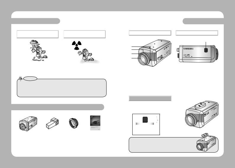
Do not expose the camera to rain |
|
Do not expose the camera to |
or other types of liquids. |
|
radioactivity. |
May cause a product malfunction.Wipe dry any |
Radioactivity exposure may damage the CCD. |
liquids. Liquids may contain minerals that are |
|
corrosive to electronic components. |
|
Notes
•Exposure to the spotlights or objects reflecting bright light, smearing or blooming may occur.
•Ensure that the power source complies with normal specifications before connecting it to the camera.
Components and Accessories
1 |
2 |
3 |
4 |
1 Ultra High Resolution Camera SCB-2000
2 Auto iris lens connection plug
3 C-Mount adaptor
4 Instruction manual
Overview
Front View |
|
Side View |
5
4 |
3 |
2 |
1 |
1 CCD protection cap |
: Please cover the CCD SENSOR when not using it. |
2 C-Mount lens adaptor |
: Please install this adapter when using a C-Mount Lens. |
3 CS-Mount lens adaptor |
: Please remove the C-MOUNT lens adaptor and then attach it. |
4 Back Focus clamp screw |
: Please loosen the clamp screw with a screwdriver before |
|
adjusting the Back Focal length. |
5 Auto Iris Lens Connector |
|
Bottom View
6 Tripod Mounting Bracket Screw Hole |
6 |
|
|
|
|||||||||||||||||||||||||||||||||||||||||||
|
|
|
|
||||||||||||||||||||||||||||||||||||||||||||
Used to fix the camera on a bracket or tripod. |
|
|
|
|
|||||||||||||||||||||||||||||||||||||||||||
The screw sizes for this hole are as follows: |
|
|
|
|
|||||||||||||||||||||||||||||||||||||||||||
|
|
|
|
|
|
|
|
|
|
|
|
|
|
|
|
|
|
|
|
|
|
|
|
|
|
|
|
|
|
|
|
|
|
|
|
|
|
|
|
|
|
|
|
|
|
|
|
|
|
|
|
|
|
|
|
|
|
|
|
|
|
|
|
|
|
|
|
|
|
|
|
|
|
|
|
|
|
|
|
|
|
|
|
|
|
|
|
|
|
|
|
|
|
|
|
1/4"-20 UNC (20 THREAD) L:4.5mm±0.2mm (ISO standard), or 0.197" (ASA standard)
You can separate the Tripod Mounting Bracket and install it on the top or bottom of the camera. Make sure to use the Tripod Mounting Bracket when fixing the camera to a bracket or tripod. Otherwise the camera may not be secure, or the internal circuitry of the camera may be damaged.
COLOR CCD CAMERA 8 User Guide |
COLOR CCD CAMERA 9 User Guide |
Overview
Rear View
7

 9
9
8
*High Voltage Type
7 Power lamp : Lights up when the correct power is supplied to the camera.
8Function Setup Button
•SETUP button :Displays the menu on the screen and uses enter sub menu. •Up&Down button : Used to move the cursor up or down in the menu screen. •Left&Right button :Used to move the cursor left or right in the menu screen.
9Video output terminal :
Sends video signal and connects to the video input terminal of the monitor.
Power input terminal : Connects to the power appropriate to each model.
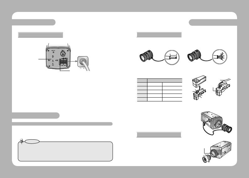
Installation
LENS
The lens is not supplied with this camera. Purchase a lens suitable for your environment. This camera accepts the auto iris lens and both C-and CS-mount lens.
Notes
•To use the functions of this camera effectively it is recommended that a DC type Auto Iris lens is used.
•Keep the lens surface clean, if it becomes contaminated with dirt or fingerprints the picture quality suffers.
 When Using Auto Iris Lens
1.Strip the insulation of the auto iris lens cable 8mm from the end.
8mm
Installation
2.Strip the insulation of the core of the auto iris lens cable to expose a 2mm length.
2mm
3.Remove the cover of the auto iris lens connector plug and solder the lens cable to the connector pin of the plug.
|
|
LENS |
Lens cable |
|
Pin No. |
DC |
VIDEO |
Connector |
|
No.1 Pin |
Damping - |
Red (power) |
||
No.3 Pin |
||||
No.2 Pin |
Damping + |
NC |
||
No.1 Pin |
||||
No.3 Pin |
Drive + |
White (video signal) |
No.4 Pin |
|
No.4 Pin |
Drive - |
Black (GND) |
No.2 Pin |
4. Please replace the auto iris lens connection plug cover and take off the CCD protection cap, and then attach the auto iris lens to the camera by
screwing it in clockwise.
5. Please insert the connection plug that is connected to the auto iris lens cable into the auto lens connector, which is located on the side of the camera.
 When using a C-Mount lens
Please take off the CCD protection cap and attach the C-Mount lens to the camera by screwing it in clockwise.
COLOR CCD CAMERA 10 User Guide |
COLOR CCD CAMERA 11 User Guide |
 Loading...