How it Works
Log In / Sign Up
0
My Files
0
My Downloads
185939
History
Account Settings
Log Out
Buy Points
How it Works
FAQ
Contact Us
Questions and Suggestions
Users
show menu
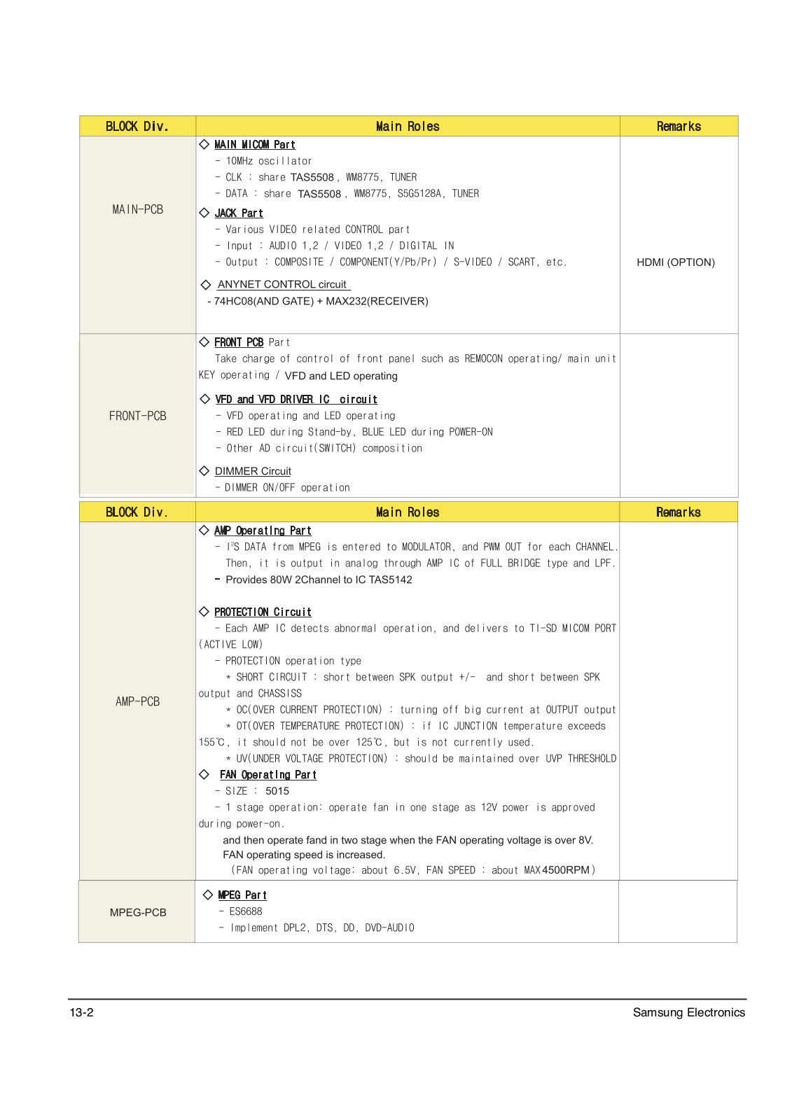
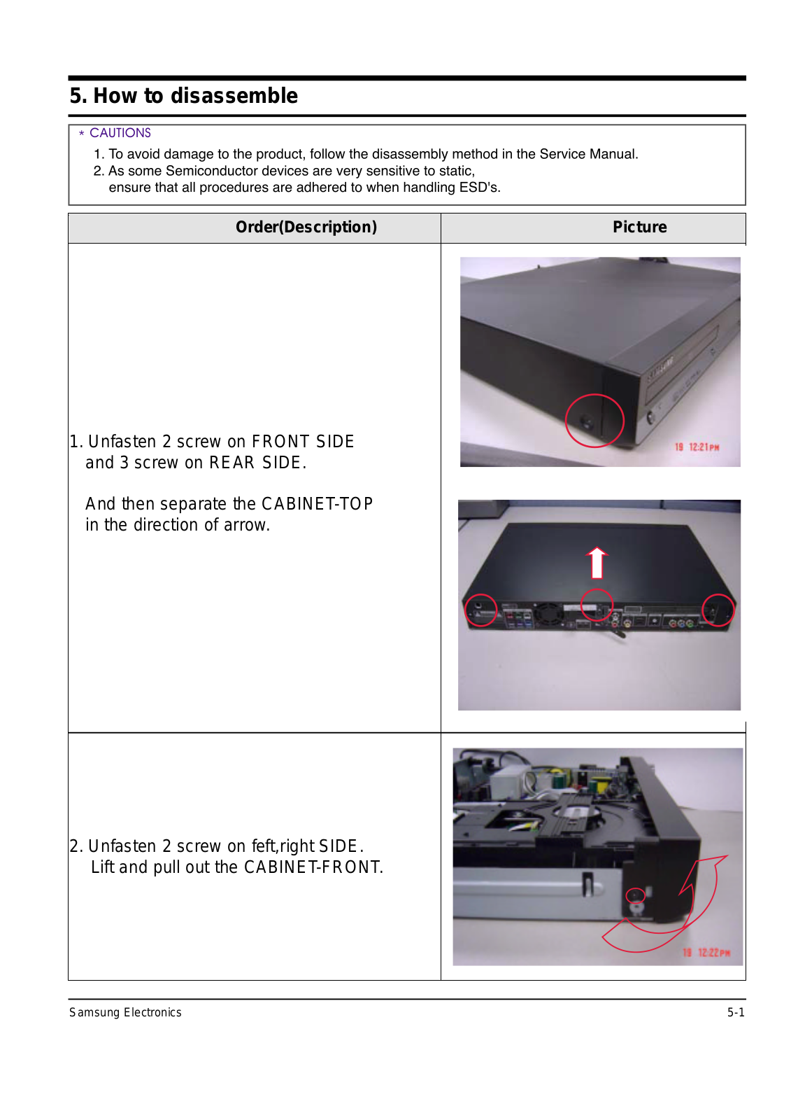
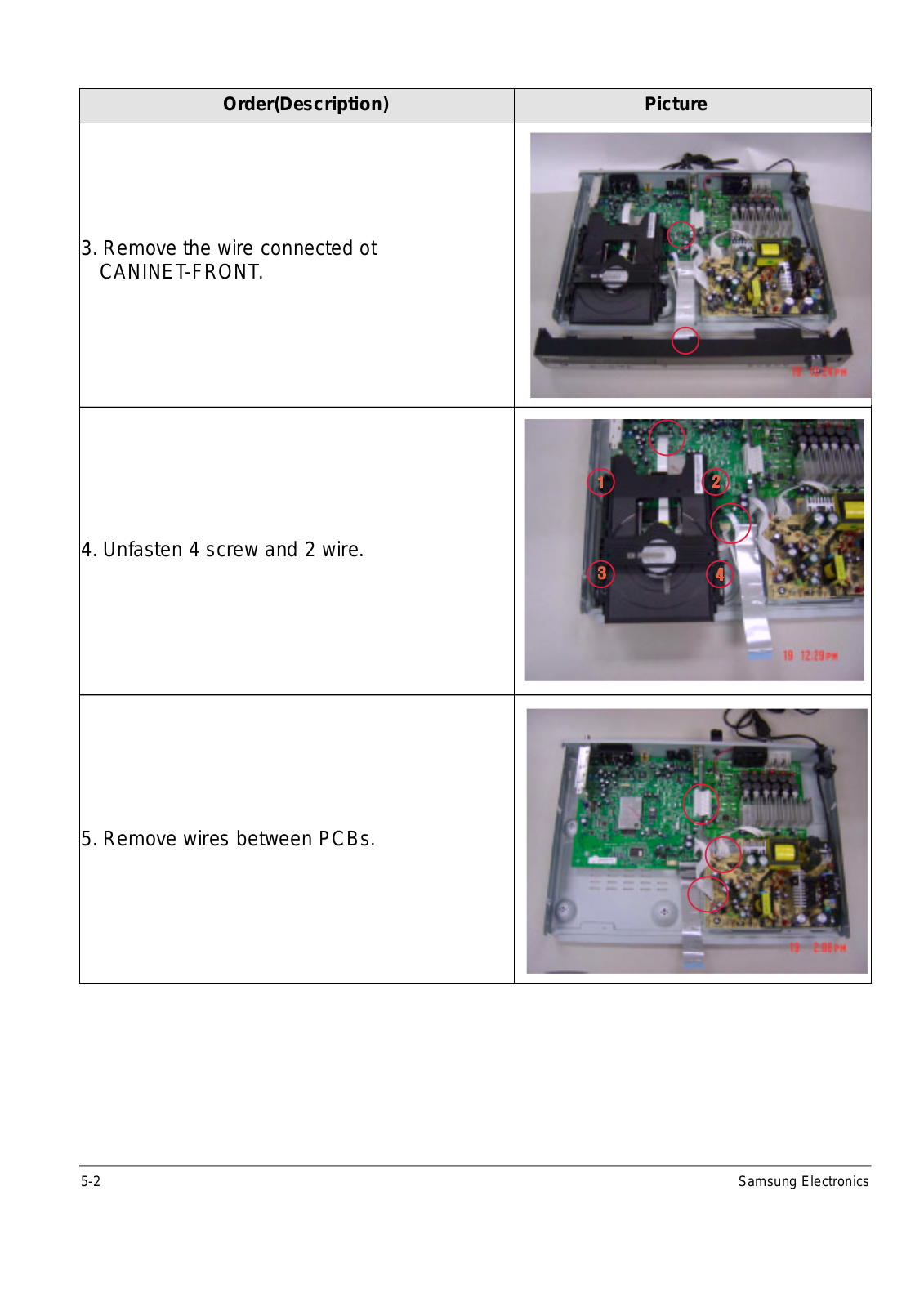
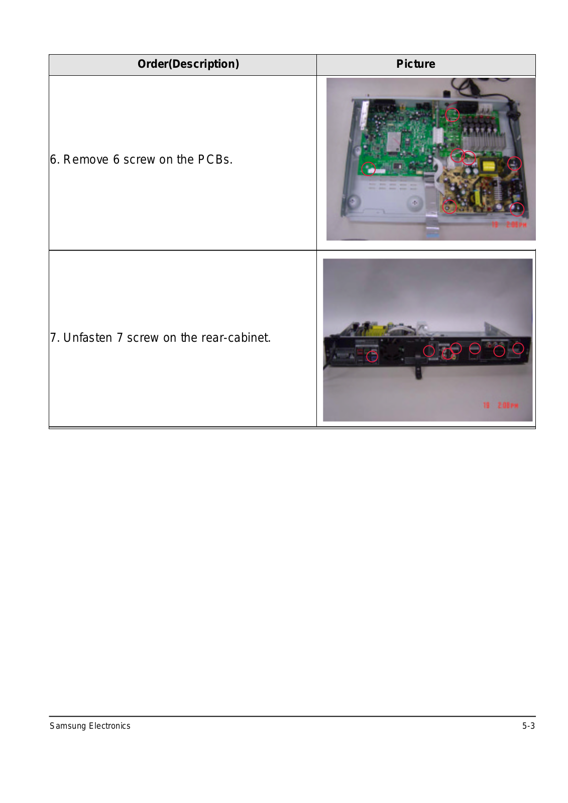
Samsung
Loading...
H
HS40
HS50A
HS70A
HSN-A80PC
HSN-A80VC
HSN-B87PW
HSN-R67FW
HSN-S62PR
HT-BD1250
HT-BD1250R
HT-BD2E
HT-BD7200
HT-BD7200T/XAA
HT-C453
HT-C460
HT-D300
HT-D455
HT-D5000
HT-D5000WXZF
HT-D5300
HT-D553
HT-D5530K
HT-D5550
HT-D555K
HT-D6500W-ZA
HT-D7100
HT-DB120
2
HT-DB1850
HT-DM550
4
HT-DS400
HT-DS600
HT-E5530
2
HT-E6730W-ZA
HT-E6750W
HT-E8000
HT-E8200
HT-EM35-ZA
HT-EM45-ZA
HT-F450BK
HT-F4530
HT-F5500
HT-F5550K
HT-H5550K
HT-H5550W
HT-H7500WM
HT-J5500K
HT-J7500W
HT-KD500
HT-KD800
5
HT-KP30
HT-KX20
HT-P1200
HT-Q100
HT-Q20
HT-SB1R
HT-TKP75
HT-TKQ25
HT-TKX500
HT-TKZ215
HT-TKZ425
HT-TP75R
HT-TQ22R
HT-TQ25
HT-TWZ312
HT-TXQ100
HT-TZ325
HT-WX70
HT-X20TD
HT-X250
HT-X30
HT-X620
HT-X720T
HT-XQ100
HT-Z215
HT-Z220
HT-Z310
HT1K01-57A
HTDL100
HTZ-420
2
HV-Z365AB
HV-Z367CUN
HW-C500
HW-C700B
HW-D350/ZA
HW-D551
HW-E350-ZA
HW-E450C
HW-F850-ZA
HW-FM45C-ZA
HW-FM55C
HW-H430
2
HW-H600-ZA
HW-H7501/ZA
HW-J355
2
HW-J355-ZA
HW-J560
HW-J6501
HW-K360/ZA
HW-K430
HW-K450/ZA
Loading...
Loading...
Nothing found
HT-KX20
User Manual [ru]
39 pgs
9.25 Mb
0
Manual [it]
39 pgs
9.47 Mb
0
Manual
39 pgs
9.47 Mb
0
Service Manual
65 pgs
15.48 Mb
1
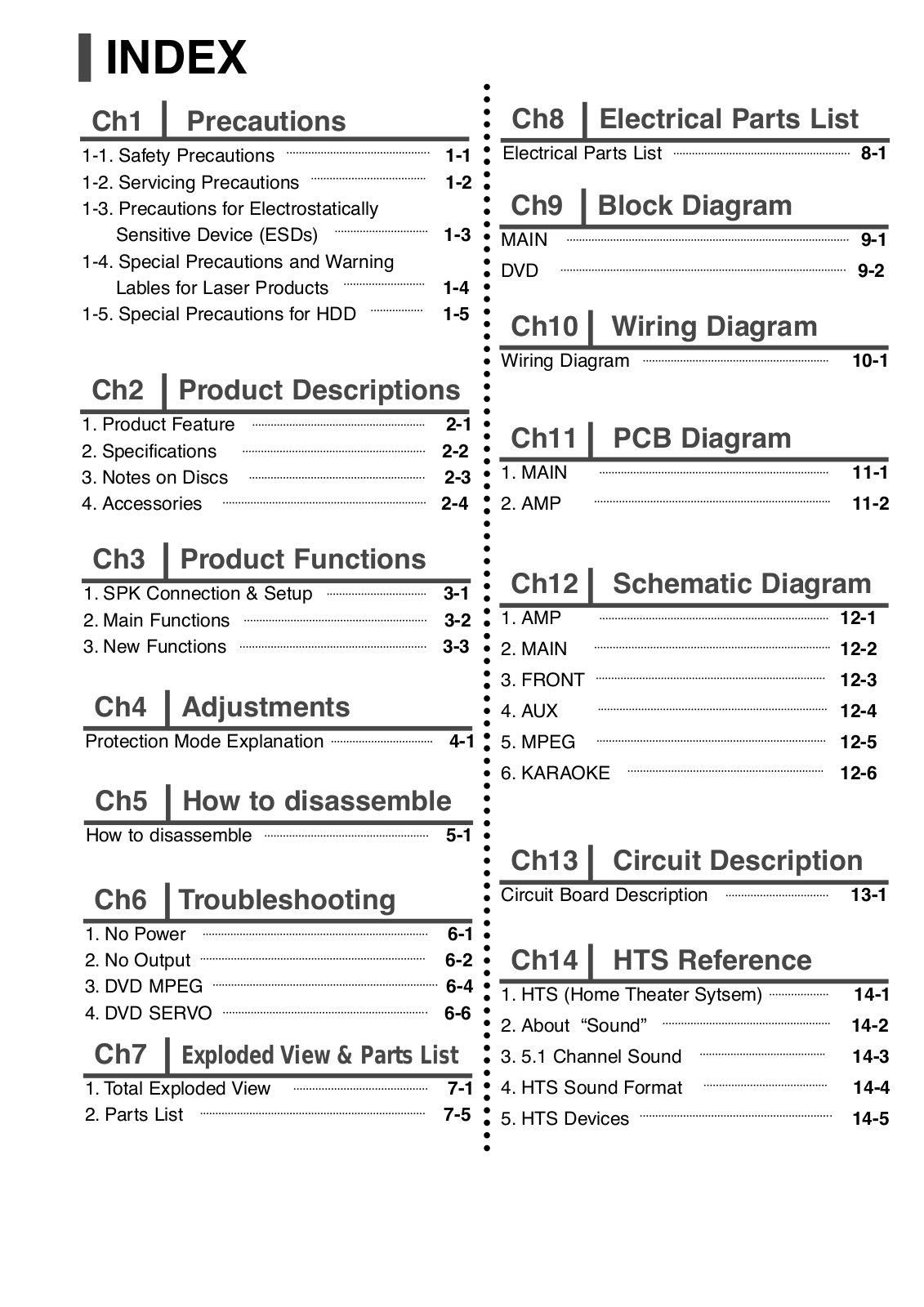
Table of contents
Loading...
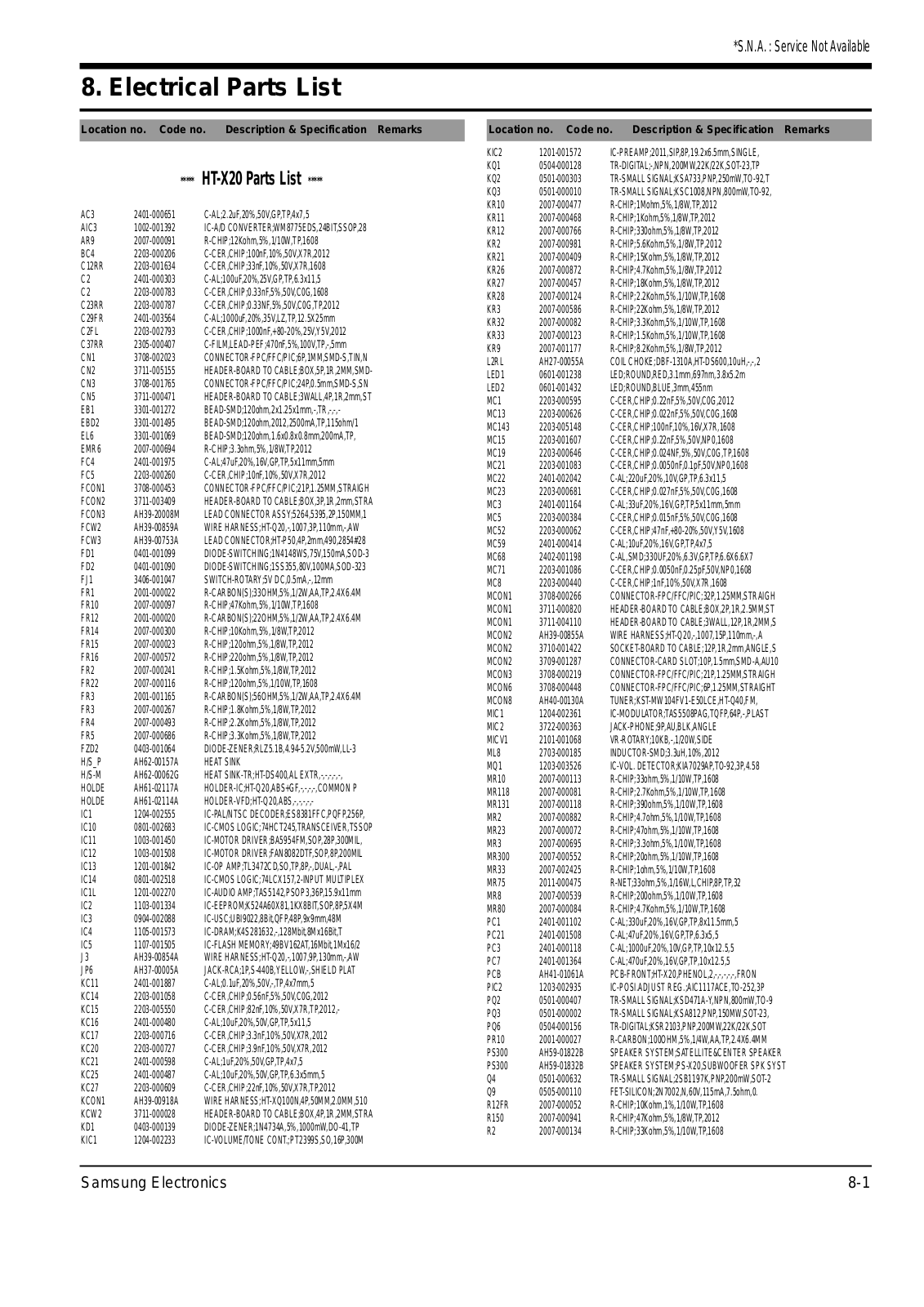
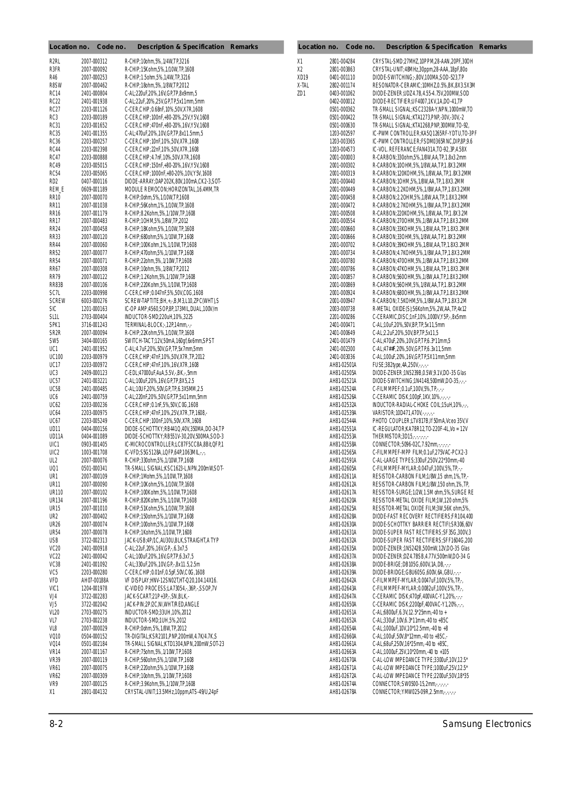
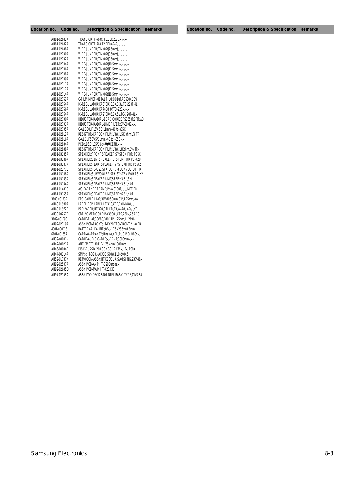
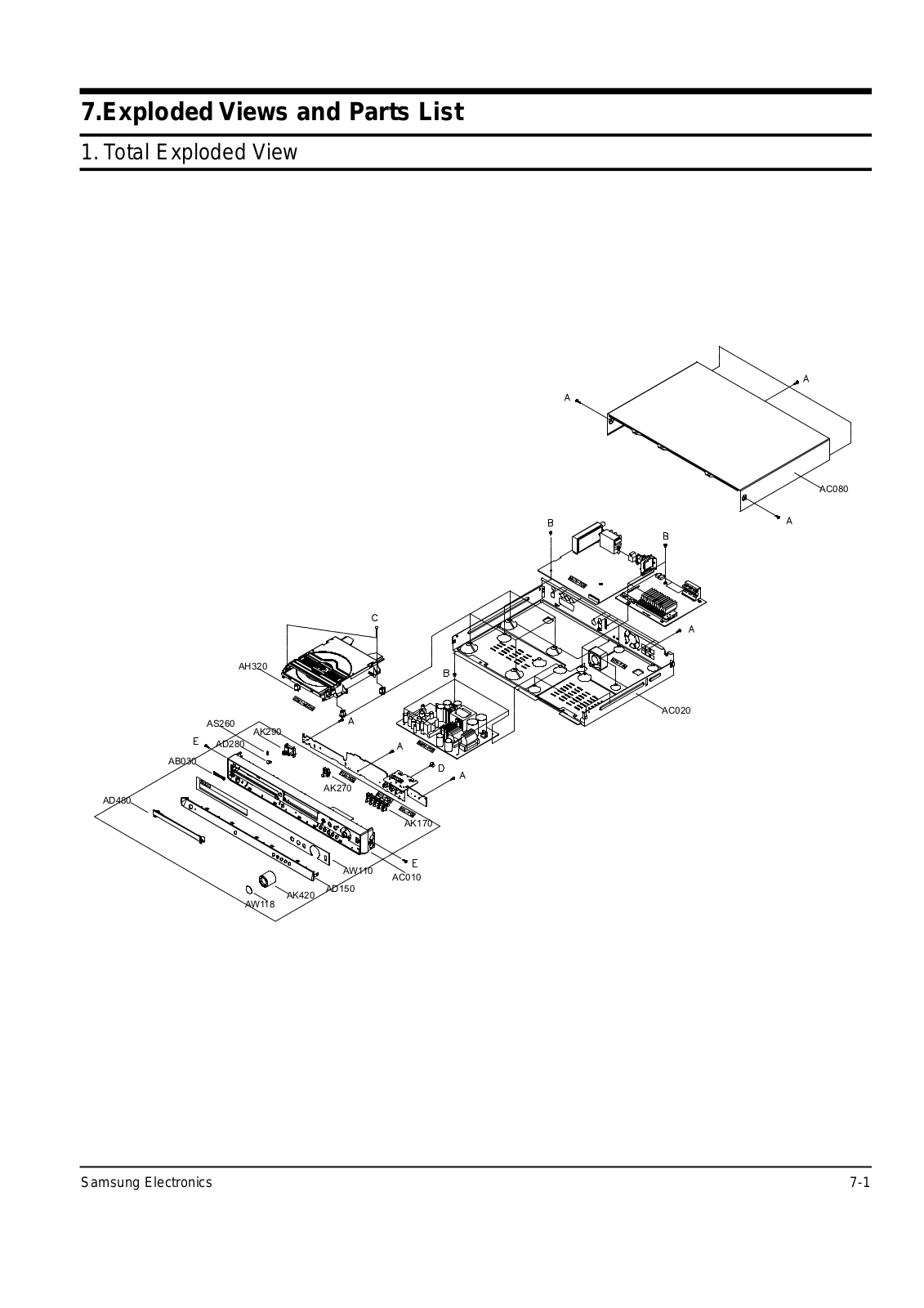
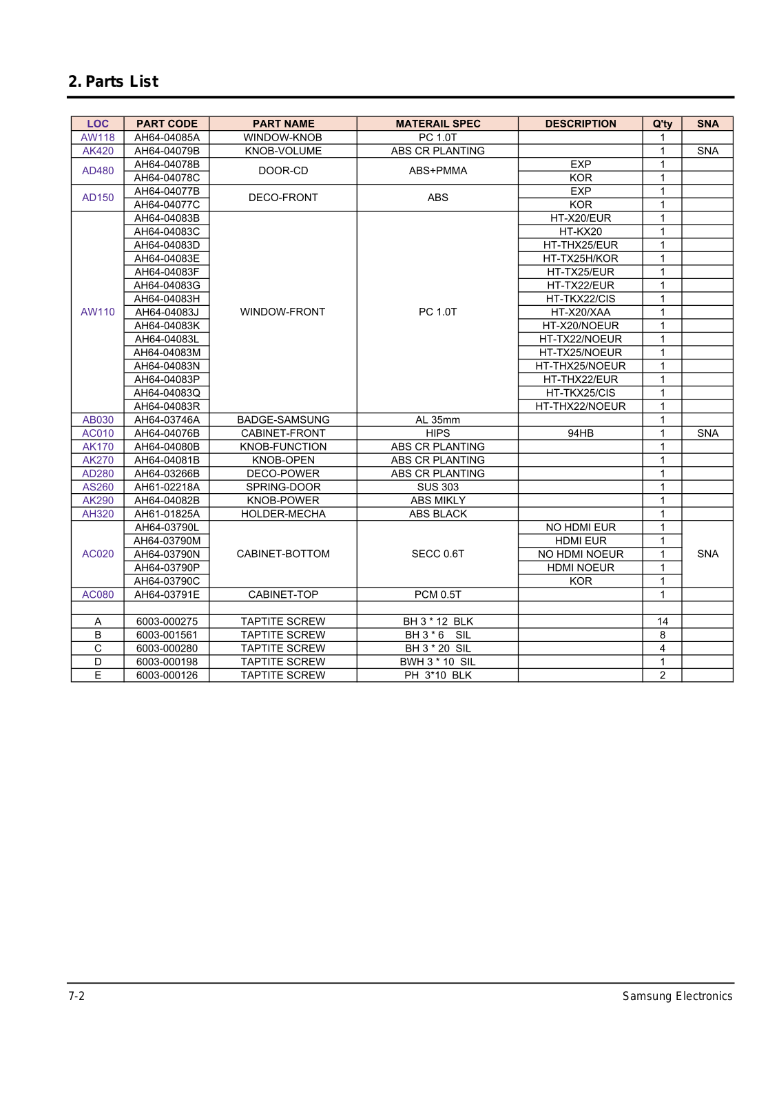
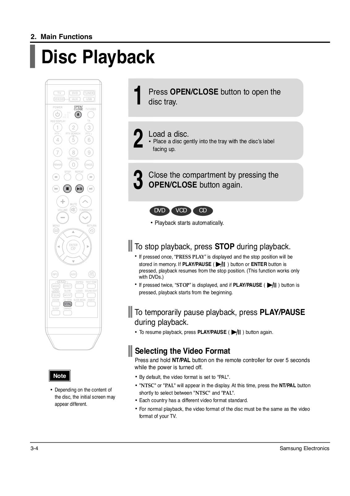
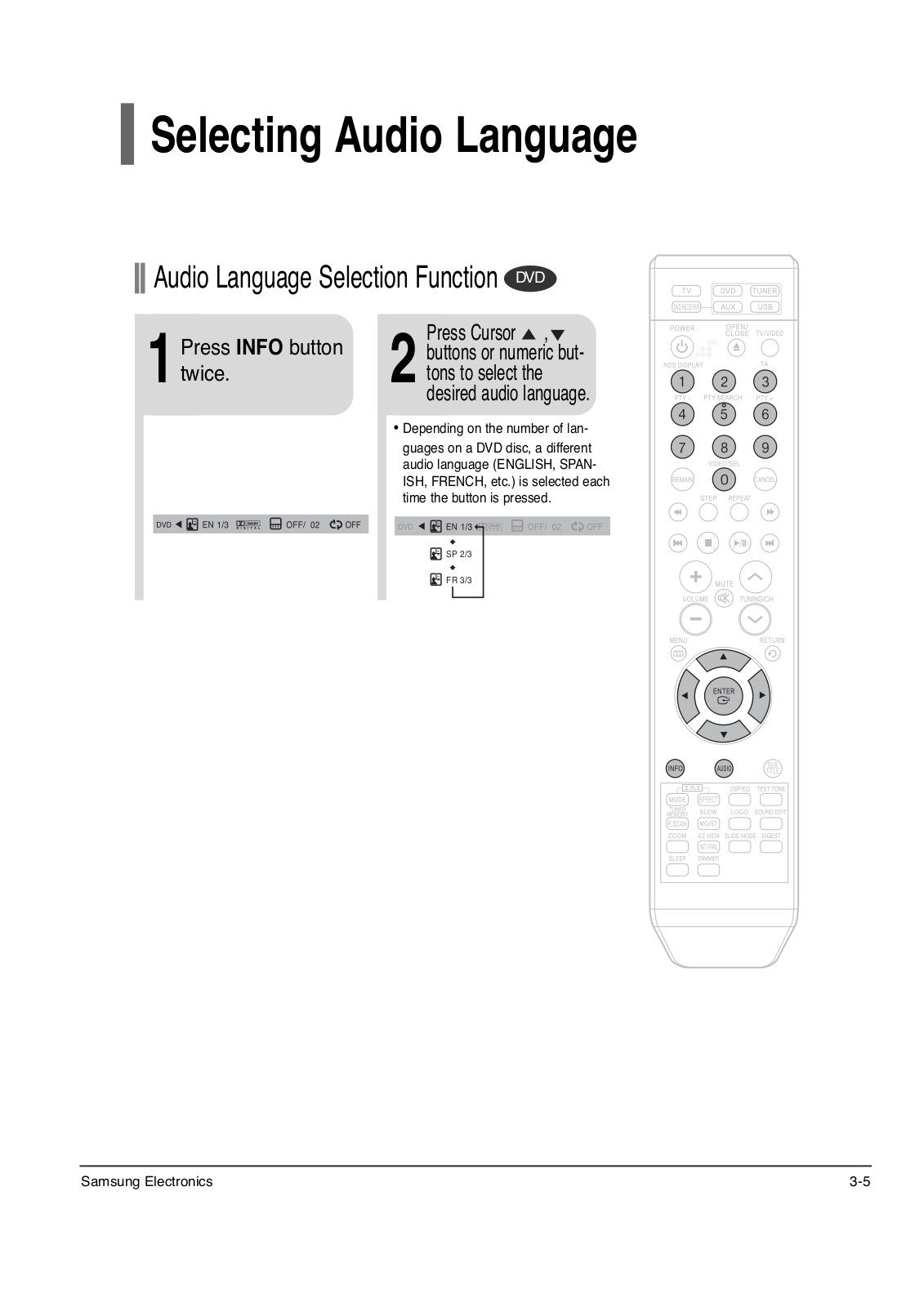
Samsung HT-KX20, HT-THX22, HT-THX25, HT-TKX22, HT-TKX25 Service Manual
...
Samsung HT-KX20, HT-THX22, HT-THX25, HT-TKX22, HT-TKX25, HT-TX22, HT-TX25, HT-X20 Service Manual
Download
5
(
2
)
Loading...
+
45
hidden pages
Unhide
You need points to download manuals.
1 point = 1 manual.
You can buy points or you can get point for every manual you upload.
Buy points
Upload your manuals
 Loading...