


HS70A
Service Manual
(Empty page)

HS70A
Service Manual
English
SM-HS70A-ENG-02
(Empty page)

Safety Requirements
■Classifications
−Type of protection against electric shock: Class I
−Degree of protection against electric shock (when the patient is in physical contact): Type BF or CF applied part
−Degree of protection against harmful ingress of water: Ordinary equipment
−Degree of safety of application in the presence of a flammable anesthetic material with air or with oxygen or nitrous oxide: Equipment not suitable for use in the presence of a flammable anesthetic mixture with air or with oxygen or nitrous oxide.
−Mode of operation: Continuous operation
■Electromechanical safety standards met
−Medical Electrical Equipment, Part 1: General Requirements for Basic Safety and Essential Performance IEC 60601-1:2005/A1:2012
−Medical Electrical Equipment, Part 1-2: General Requirements for Basic Safety and Essential Performance - Collateral Standards: Electromagnetic Compatibility - Requirements and Tests IEC 60601-1-2:2007
−Medical Electrical Equipment, Part 1-6: General Requirements for Basic Safety and Essential Performance - Collateral Standards: Usability IEC
60601-1-6:2010
−Medical Electrical Equipment, Part 2-37: Particular Requirements for the Basic Safety and Essential Performance of Ultrasonic Medical Diagnostic and Monitoring Equipment IEC 60601-2-37:2007
−Medical Electrical Equipment, Part 1: General Requirements for Safety IEC
60601-1:1988, A1:1991, A2:1995
−Medical Electrical Equipment, Part 1-1: General Requirements for Safety - Collateral Standards: General Requirements for Medical Electrical Systems
IEC 60601-1-1:2000
−Medical Electrical Equipment, Part 1-2: General Requirements for Safety - Collateral Standards: Electromagnetic Compatibility - Requirements and Tests IEC 60601-1-2:2001, A1:2004
−Medical Electrical Equipment, Part 1-4: General Requirements for Safety - Collateral Standards: Programmable Electrical Medical Systems IEC
60601-1-4:1996, A1:1999

−Medical Electrical Equipment, Part 2-37: Particular Requirements for the Basic Safety and Essential Performance of Ultrasonic Medical Diagnostic and Monitoring Equipment IEC 60601-2-37:2001, A1:2004, A2:2005
−Medical Devices - Application of Risk Management ISO 14971:2007
−Medical Electrical Equipment, Part 1: General Requirements for Safety UL
60601-1:2003
−Medical Electrical Equipment - Part 1: General Requirements for Safety
CAN/CSA C22.2 No. 601.1-M90:1990, R2003, R2005
−Biological Evaluation of Medical Devices – Part 1: Evaluation and Testing
ISO 10993-1: 2009
−Standard Means for Reporting the Acoustic Output of Medical Diagnostic Ultrasonic Equipment IEC 61157:2007
■Declarations
CSA mark with the indicators “C” and “US” means that the product is certified for both the U.S. and Canadian markets, to the applicable U.S. and Canadian standards.
This is the manufacturer’s declaration of product compliance with applicable EEC directive (s) and the European notified body.
This is the manufacturer’s declaration of product compliance with applicable EEC directive (s).
This is the GMP symbol for Korean Good
Manufacturing Practice quality system regulation.

Precautions for Use
Read this service manual to familiarize yourself thoroughly with repair procedures and important safety information before attempting to service the product.
■Refer to this service manual when you are servicing the product. Please familiarize yourself with the safety precautions in 'Chapter 1. Safety' and 'Chapter 4. Maintenance' in particular.
■This product is an ultrasound diagnosis device and cannot be used for other purposes.
■This product may only be serviced by a service engineer of Samsung Medison or an authorized engineer. Samsung Medison is not responsible for any problems caused by an unauthorized person servicing the product.
■The manufacturer is not responsible for any damage to this product caused by user carelessness and/or neglect.
■The content of this service manual is subject to change without prior notice.
■Products that are not manufactured by Samsung Medison are indicated with the trademarks of their respective owners.
■The following terms are used to highlight safety precautions that the user must be aware of:
DANGER
WARNING
CAUTION
NOTE
Describes precautions necessary to prevent user hazards of great urgency. Ignoring a DANGER warning will risk life-threatening injury.
Used to indicate the presence of a hazard that can cause serious personal injury, or substantial property damage.
Indicates the presence of a hazard that can cause equipment damage.
A piece of information useful for installing, operating and maintaining a system. Not related to any hazard.

Revision History
The revision history of this manual is as follows:
|
|
|
|
|
|
|
|
|
|
|
|
|
|
|
|
|
|
|
VERSION |
DATE |
REASON FOR CHANGE |
||||||||||||||
|
|
|
|
|
|
|
|
|
|
|
|
|
|
|
|||
|
|
|
|
|
|
|
|
|
|
|
|
|
|
|
|
|
|
|
|
v1.00.00 |
2015.07.07 |
|
|
Initial Release |
|||||||||||
|
|
|
|
|
|
|
|
|
|
||||||||
|
|
|
|
|
|
|
|
|
|
|
|
|
|
|
|
|
|
|
|
V2.00.00 |
2016.09.22 |
|
Software upgrade / Parts change |
||||||||||||
|
|
|
|
|
|
|
|
|
|
|
|
|
|
|
|
|
|
If You Need Assistance
If you need any assistance with the equipment, please contact the Samsung Medison Customer Service Department or your local vendor.

|
Table of Contents 1 |
Table of Contents |
|
Chapter 1. Safety |
|
Purpose of Use....................................................................................................................... |
2 |
Contraindications............................................................................................................. |
2 |
Safety Information.................................................................................................................. |
3 |
Safety Symbols................................................................................................................ |
3 |
Symbols ........................................................................................................................... |
6 |
LABEL.............................................................................................................................. |
6 |
Electrical Safety...................................................................................................................... |
7 |
Prevention of Electric Shocks.......................................................................................... |
7 |
ECG-related Information.................................................................................................. |
10 |
ESD ................................................................................................................................. |
10 |
EMI .................................................................................................................................. |
11 |
EMC................................................................................................................................. |
12 |
Mechanical Safety .................................................................................................................. |
20 |
Moving the Equipment..................................................................................................... |
20 |
Safety Notes .................................................................................................................... |
21 |
Biological Safety .................................................................................................................... |
24 |
ALARA Principle .............................................................................................................. |
24 |
Environmental Protection ..................................................................................................... |
38 |
Chapter 2. Introduction |
|
Product Specifications .......................................................................................................... |
2 |
Product Configuration ........................................................................................................... |
5 |
The Monitor ..................................................................................................................... |
7 |
The Control Panel............................................................................................................ |
9 |
The Console .................................................................................................................... |
16 |
Peripheral Devices........................................................................................................... |
18 |

2 HS70A Service Manual
Probes............................................................................................................................. |
21 |
Accessories..................................................................................................................... |
22 |
Optional Functions .......................................................................................................... |
22 |
Chapter 3. Installing the Product |
|
Transporting........................................................................................................................... |
2 |
Unpacking the Product ......................................................................................................... |
3 |
Installation Environment....................................................................................................... |
4 |
Installing the Product ............................................................................................................ |
5 |
Connecting Peripherals................................................................................................... |
7 |
System Power ........................................................................................................................ |
9 |
Turning the Power On ..................................................................................................... |
9 |
Shutting Down the System .............................................................................................. |
10 |
System Settings..................................................................................................................... |
11 |
General ........................................................................................................................... |
12 |
Scan Mode ...................................................................................................................... |
17 |
Display............................................................................................................................. |
20 |
Annotate.......................................................................................................................... |
24 |
Peripheral Device Settings.............................................................................................. |
29 |
User Defined Keys .......................................................................................................... |
33 |
Network ........................................................................................................................... |
35 |
DICOM Setup (optional).................................................................................................. |
37 |
Options............................................................................................................................ |
49 |
System Information ......................................................................................................... |
51 |
Chapter 4. Product Inspection |
|
Inspecting Functions............................................................................................................. |
2 |
Basic Inspections ............................................................................................................ |
2 |
Detailed Inspections........................................................................................................ |
4 |
|
Table of Contents 3 |
Chapter 5. Product Structure |
|
Overview ................................................................................................................................. |
3 |
System Block Diagram .......................................................................................................... |
5 |
Basic Structure of UGEO HS70A .......................................................................................... |
7 |
Overview.......................................................................................................................... |
7 |
Ultrasound System Part................................................................................................... |
8 |
PC Part ............................................................................................................................ |
9 |
User Interface Part .......................................................................................................... |
10 |
AC to Power Module........................................................................................................ |
10 |
Ultrasound System Part......................................................................................................... |
10 |
PSA.................................................................................................................................. |
10 |
Analog Control................................................................................................................. |
12 |
Beam Former Board........................................................................................................ |
14 |
CW Board........................................................................................................................ |
18 |
Back End Board............................................................................................................... |
21 |
PC Part .................................................................................................................................... |
26 |
PC Module....................................................................................................................... |
26 |
Software DSC.................................................................................................................. |
27 |
Rear Board ...................................................................................................................... |
29 |
Power Supply................................................................................................................... |
30 |
User Interface Part ................................................................................................................. |
32 |
Control Panel................................................................................................................... |
32 |
Docking CP Board ........................................................................................................... |
33 |
Touch Panel .................................................................................................................... |
34 |
Monitor............................................................................................................................. |
35 |
Interconnect Diagram ............................................................................................................ |
36 |

4 HS70A Service Manual
Chapter 6. Service Mode |
|
Enter Installation Key ............................................................................................................ |
2 |
System Information ............................................................................................................... |
4 |
Windows Mode ...................................................................................................................... |
5 |
Accessing method........................................................................................................... |
5 |
Admin Mode ........................................................................................................................... |
6 |
Accessing method........................................................................................................... |
6 |
Admin Mode Functions ................................................................................................... |
7 |
Adding and Deleting Options ............................................................................................... |
11 |
Adding an Option ............................................................................................................ |
12 |
Chapter 7. Troubleshooting |
|
Power Issues.......................................................................................................................... |
2 |
Power Does Not Turn On................................................................................................ |
2 |
Power Does Not Turn Off................................................................................................ |
2 |
Power Turns Off by Itself................................................................................................. |
3 |
Monitor.................................................................................................................................... |
4 |
Nothing Is Displayed on the Screen................................................................................ |
4 |
Screen is Discolored ....................................................................................................... |
4 |
Error Messages...................................................................................................................... |
5 |
Error Occurs during Booting............................................................................................ |
5 |
Image....................................................................................................................................... |
6 |
2D Mode: There is No IMAGE ECHO or IMAGE FORMAT............................................ |
6 |
Lines (Noise) Appear in 2D Mode Image........................................................................ |
6 |
M, C, PW, CW Mode Trouble ......................................................................................... |
6 |
Error Code .............................................................................................................................. |
7 |
Chapter 8. Disassembly and Assembly |
|
Caution ................................................................................................................................... |
2 |

|
Table of Contents 5 |
Preparation ...................................................................................................................... |
2 |
Disassembling the Product................................................................................................... |
3 |
Front Cover Disassembly ................................................................................................ |
3 |
Rear Cover Disassembly................................................................................................. |
5 |
Control Panel Disassembly.............................................................................................. |
7 |
Monitor Disassembly ....................................................................................................... |
8 |
Monitor Arm Disassembly................................................................................................ |
9 |
Assembling the Product ........................................................................................................ |
11 |
Chapter 9. Probes |
|
Probe ....................................................................................................................................... |
2 |
Ultrasound Transmission Gel .......................................................................................... |
9 |
Using Sheaths ................................................................................................................. |
10 |
Probe Safety Precautions ................................................................................................ |
11 |
Cleaning and Disinfecting the Probe ............................................................................... |
13 |
Chapter 10. Maintenance |
|
Product Maintenance............................................................................................................. |
2 |
Cleaning and disinfecting................................................................................................. |
2 |
Air Filter Management ..................................................................................................... |
4 |
Accuracy Checks............................................................................................................. |
5 |
Information Maintenance....................................................................................................... |
6 |
Backing up User Setting .................................................................................................. |
6 |
Backing Up Patient Information....................................................................................... |
6 |
Software........................................................................................................................... |
6 |
Chapter 11. Service Part List |
|
Body Cover Parts ................................................................................................................... |
2 |
System Parts........................................................................................................................... |
8 |

6 HS70A Service Manual
Control Panel Parts ............................................................................................................... |
12 |
System Cable Parts ............................................................................................................... |
16 |
Chapter 12. Parts Renewal |
|
Board....................................................................................................................................... |
2 |

Chapter 1
|
Safety |
Purpose of Use ........................................................................................................... |
2 |
Restrictions ............................................................................................................................... |
2 |
Safety Information ...................................................................................................... |
3 |
Safety Symbols ......................................................................................................................... |
3 |
LABEL....................................................................................................................................... |
6 |
Electrical Safety.......................................................................................................... |
7 |
Prevention of Electric Shock..................................................................................................... |
7 |
ECG-Related Information ....................................................................................................... |
10 |
ESD......................................................................................................................................... |
10 |
EMI.......................................................................................................................................... |
11 |
EMC ........................................................................................................................................ |
12 |
Mechanical Safety..................................................................................................... |
20 |
Moving the Equipment ............................................................................................................ |
20 |
Safety Notes ........................................................................................................................... |
21 |
Biological Safety....................................................................................................... |
24 |
ALARA Principle ..................................................................................................................... |
24 |
Environmental Protection ........................................................................................ |
38 |

1 - 2 HS70A Service Manual
Purpose of Use
Ultrasound diagnostic system and probes were designed for obtaining ultrasound images and analyzing human blood. The clinical applications include:
Fetal/Obstetrics, Abdominal, Gynecology, Pediatric, Small Organ, Neonatal Cephalic, Adult Cephalic, Trans-rectal, Trans-vaginal, Muscular-Skeletal (Conventional, Superficial), Urology, Cardiac Adult, Cardiac Pediatric and Peripheral vessel.
|
|
For detailed information on applications and presets, |
|
|
|
NOTE |
please refer to the |
||||
|
HS70A User Manual |
. |
|||
|
|
||||
|
|
|
|
|
|
Restrictions
This product must not be used for ophthalmological applications, or any other use that involves the ultrasound beam passing through the eye.
|
|
For information on the use or clinical application of this product, |
|
|
|
CAUTION |
please |
||||
|
refer to the HS70A User Manual |
. |
|||
|
|
||||
|
|
|
|
|
|
Chapter 1 Safety 1 - 3
Safety Information
Please read the following safety information before using this product. This provides explanation about the ultrasound system, the probes, the recording devices, and any of the optional equipment.
This product is intended for use by, or by the order of, and under the supervision of, a licensed physician who is qualified for direct use of medical devices.
Prolonged use of three-dimensional ultrasound (3D, 4D) by an unqualified individual, such as to produce a commemorative photograph or video of the fetus, may have an adverse effect on the fetus.
Please use the 3D ultrasound diagnostic imaging system for appropriate purposes only, since using it for non-diagnostic purposes such as recording videos of the fetus may adversely affect the fetus.
Safety Symbols
The International Electro Technical Commission (IEC) has established a set of symbols for medical electronic equipment, which classify a connection or warn of potential hazards. The classifications and symbols are shown below.
Symbols |
Description |
|
|
Warning: The accompanying information must be followed to prevent serious accidents and/or damage to property.
Caution: The accompanying information helps to prevent minor accidents and/or damage to property.
Refer to the user manual.
1 - 4 HS70A Service Manual
Symbols |
Description |
|
|
|
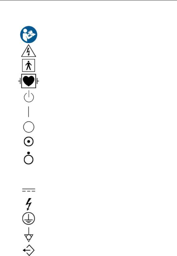
Follow the user manual. |
|
|
|
Caution: Risk of electric shock |
|
|
|
Type BF applied part (Classification based on degree of protection |
|
against electric hazard) |
|
|
|
Defibrillation-proof type CF applied part (Classification based on |
|
degree of protection against electric hazard) |
|
|
|
Power on/off |
|
|
|
Power on |
|
|
|
Power off |
|
|
|
Product is partially powered on |
|
|
|
Power off for part of the product |
|
|
V~ |
AC (alternating current) voltage source |
|
|
|
|
|
Direct current voltage source |
|
|
|
Dangerous voltage (Indicates dangerous voltages over 1000V AC or |
|
1500V DC) |
|
|
|
Protective earth (ground) |
|
|
|
Equipotentiality |
|
|
|
Data output port |
|
|

Chapter 1 Safety 1 - 5
Symbols |
Description |
|
|
|
Data input port |
|
|
|
Data input/output port |
|
|
|
Input port |
|
|
|
Output port |
|
|
|
Print remote output |
|
|
|
Foot switch port |
|
|
|
ECG port |
|
|
|
USB port |
|
|
|
Network port |
|
|
|
Microphone port |
|
|
|
Probe port |
|
|
IPX 1 |
Dripping-proof device: Protected against vertically falling water |
|
|
IPX 7 |
Immersion-proof device: Protected against the effects of temporary |
immersion in water |
|
|
|
IPX 8 |
Submersion-proof device: Protected against the effects of continuous |
immersion in water |
|
|
|
1 - 6 HS70A Service Manual
Symbols |
Description |
|
|
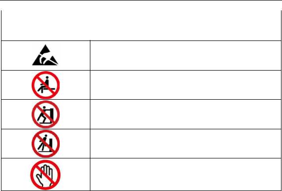
Caution: Electrostatic sensitive devices (ESD)
Do not sit on the product.
Do not push the product.
Do not lean against the product.
Be mindful of the space. Do not place a finger, and or any part of your body in the space.
LABEL
Phrases containing the words ‘warning’ and/or ‘caution’ are displayed on the product’s surface in order to protect it.
Chapter 1 Safety 1 - 7
Electrical Safety
This equipment is categorized as a Class I device with Type BF or Type CF (ECG) applied parts.
Prevention of Electric Shock
In a hospital environment, dangerous electric current may occur as a result of the potential difference between a contactable conductive part and connected equipment in treatment rooms. The solution to the problem is consistent equipotential bonding. Medical equipment is connected with connecting leads made up of sockets which are angled to the equipotential bonding network in medical rooms.
[Figure 1.1 Equipotential Bonding]
Additional equipment connected to medical electrical equipment must comply with the pertinent IEC standards (e.g. IEC 60950/EN 60950 for data processing equipment, IEC 60601-1/EN 60601-1 for medical devices). Furthermore, all components of the product shall comply with the requirements for medical electrical systems IEC 60601-1-1/EN 60601-1-1. Any person connecting additional equipment to the signal input and output ports of medical electrical equipment must verify that the equipment complies with IEC 60601-1-1/EN 60601-1-1.

1 - 8 HS70A Service Manual
■ Electric shocks may result if this system, including all of its externally mounted recording and monitoring devices, is not properly grounded.
■ Never open the cover of the product. Hazardously high voltage flows through the product. All internal adjustments and replacements must be made by a qualified Samsung Medison Customer Service Department.
■ Always check the product's casing, cables, cords, and plugs for damage before using the product. Disconnect and do not use the power source if the face is cracked, chipped, torn, the housing is damaged, or if the cable is abraded.
■ Always disconnect the system from the wall outlet prior to cleaning it.
WARNING |
■ All patient contact devices, such as probes and ECG leads, must be |
|
|
|
removed from the patient prior to the application of a high voltage |
|
defibrillation pulse. |
|
■ The use of flammable anesthetic gas or oxidizing gases (N2O) should |
|
be avoided. Doing so may cause an explosion. |
|
■ Avoid placing the system where it is likely to be difficult to operate, or |
|
disconnect. |
|
■ Do not use HF surgical equipment with the system. Any malfunctions |
|
in the HF surgical equipment may result in burns to the patient. |
|
■ The system must only be connected to a supply mains with protective |
|
earth to avoid risk of electric shock. |

Chapter 1 Safety 1 - 9
■The system has been designed for 100-240VAC; you should select the input voltage of any connected printer and VCR. Prior to connecting a peripheral power cord, verify that the voltage indicated on the power cord matches the voltage rating of the peripheral device.
■An isolation transformer protects the system from power surges. This continues to operate when the system is on standby.
■Do not immerse the cable in liquids. Cables are not waterproof.
■Make sure that the inside of the system is not exposed to or flooded
CAUTION |
with liquids. In such cases, fire, electric shock, injury, or damage to the |
product may occur. |
■The auxiliary socket outlets installed on this system are rated 100240VAC, with a maximum total load of 150VA. Only use these outlets for supplying power to equipment that is intended to be part of the ultrasound system. Do not connect additional multiple-socket outlets or extension cords to the system.
■Do not connect any peripheral devices not listed in this manual to the auxiliary socket outlets of the system. It may cause an electrical hazard.
■Do not touch SIP/SOP and the patient simultaneously. There is a risk of electric shock from current leakage.

1 - 10 HS70A Service Manual
ECG-Related Information
|
■ |
This product does not support ECG monitoring. Therefore, it will not |
|
|
recognize incompatible ECG signals. |
|
■ |
Do not use the ECG electrodes of HF surgical equipment. Any |
WARNING |
|
malfunctions in the HF surgical equipment may result in burns to the |
|
patient. |
|
|
■ |
Do not use ECG electrodes during cardiac pacemaker procedures or |
|
|
other electrical stimulators. |
|
■ |
Do not use ECG leads and electrodes in an operating room. |
|
|
|
ESD
Electrostatic discharge (ESD), commonly referred to as a static shock, is a naturally occurring phenomenon. ESD is most prevalent during conditions of low humidity, which can be caused by heating or air conditioning. The static shock, or ESD, is a discharge of the electrical energy buildup from a charged individual to a lesser or uncharged individual or object. An ESD occurs when an individual with an electrical energy build-up comes in to contact with conductive objects such as metal doorknobs, file cabinets, computer equipment, and even other individuals.
|
■ |
The level of electrical energy discharged from a system user or a patient |
|
|
|
to an ultrasound system can be significant enough to cause damage to |
|
|
|
the system or probes. |
|
|
■ |
Always perform the pre-ESD preventive procedures before using |
|
CAUTION |
|
connectors marked with the ESD warning label. |
|
|
- |
Apply anti-static spray to carpets or linoleum. |
|
|
|
- |
Use anti-static mats. |
|
|
- |
Ground the product to the patient table or bed. |
|
■ |
It is highly recommended that the user be given training on ESD-related |
|
|
|
warning symbols and preventive procedures. |
|
|
|
|
|

Chapter 1 Safety 1 - 11
EMI
This product complies with EMI (Electromagnetic Interference) standards. However, using the system inside an electromagnetic field can lower the quality of ultrasound images and even damage the product.
If this occurs often, Samsung Medison suggests a review of the environment in which the system is being used, to identify possible sources of radiated emissions. These emissions could be from other electrical devices used within the same room or an adjacent room. Communication devices, such as cellular phones and pagers, can cause these emissions. The existence of radios, TVs, or microwave transmission equipment nearby can also cause interference.
CAUTION |
In cases where EMI is causing disturbances, it may be necessary to relocate |
|
the system. |
|
|

1 - 12 HS70A Service Manual
EMC
Testing of the EMC (Electromagnetic Compatibility) of this system has been performed according to the international standard for EMC with medical devices (IEC 60601-1-2). This IEC standard was adopted in Europe as the European norm (EN 60601-1-2).
▐ Guidance and Manufacturer’s Declaration – Electromagnetic
Emissions
This product is intended for use in the electromagnetic environment specified below. The customer or the user of this product should assure that it is used in such an environment.
Emission Test |
Compliance |
Electromagnetic environment guidance |
|
|
|
|
|
|
|
The Ultrasound System uses RF energy only for its |
|
RF Emission |
Group 1 |
internal function. Therefore, its RF emissions are very |
|
CISPR 11 |
low and are not likely to cause any interference in nearby |
||
|
|||
|
|
electronic equipment. |
|
|
|
|
|
RF Emission |
Class A |
|
|
CISPR 11 |
|
||
|
|
||
|
|
The Ultrasound System is suitable for use in all |
|
|
|
||
Harmonic Emission |
|
establishments other than domestic and those directly |
|
Class A |
connected to the public low-voltage power supply |
||
IEC 61000-3-2 |
|||
|
network that supplies buildings used for domestic |
||
|
|
purposes. |
|
Flicker Emission |
Complies |
||
|
|||
IEC 61000-3-3 |
|
||
|
|
||
|
|
|

Chapter 1 Safety 1 - 13
▐ Approved Cables, Probes and Peripherals for EMC
Cable
Cables connected to this product may affect its emissions.
Refer to the table below for recommended cable types and lengths:
Cable |
Type |
Length |
|
|
|
VGA |
Shielded |
Normal |
RS232C |
Shielded |
Normal |
USB |
Shielded |
Normal |
LAN(RJ45) |
Twisted pair |
Any |
S-Video |
Shielded |
Normal |
Foot Switch |
Shielded |
2.99m |
B/W printer |
Unshielded Coaxial |
Normal |
MIC |
Unshielded |
Any |
Printer Remote |
Unshielded |
Any |
Audio R.L |
Shielded |
Normal |
VHS |
Shielded |
Normal |
ECG AUX input |
Shielded |
< 3m |
Parallel |
Shielded |
Normal |
Probe
The image probe used with this product may affect its emission. The probe listed in
‘Chapter 5. Probes’ when used with this product, have been tested to comply with the
group1 Class A emission as required by International Standard CISPR 11.
Peripherals
Peripherals used with this product may affect its emissions.
When connecting other customer-supplied accessories to the CAUTION system, it is the user’s responsibility to ensure the electromagnetic
compatibility of the system.
The use of cables, probes, and peripherals other than those WARNING specified, may result in increased emissions or decreased immunity
of the Ultrasound System.

1 - 14 HS70A Service Manual
Immunity Test |
IEC 60601 Test |
Compliance level |
Electromagnetic |
|
Level |
environment guidance |
|||
|
|
|||
|
|
|
|
|
|
|
|
Floors should be wood, |
|
Electrostatic |
±6KV contact |
±6KV contact |
concrete or ceramic tile. |
|
discharge (ESD) |
If floors are covered with |
|||
|
|
|||
|
±8KV air |
±8KV air |
synthetic material, the |
|
IEC 61000-4-2 |
relative humidity should be |
|||
|
|
|||
|
|
|
at least 30%. |
|
|
|
|
|
|
Electrical fast |
±2KV |
±2KV |
Mains power quality should |
|
transient/burst |
for power supply lines |
for power supply lines |
be that of a typical |
|
|
±1KV |
±1KV |
commercial or hospital |
|
IEC 61000-4-4 |
for input/output lines |
for input/output lines |
environment. |
|
|
|
|
|
|
Surge |
±1KV differential mode |
±1KV differential mode |
Mains power quality should |
|
be that of a typical |
||||
|
|
|
||
IEC 61000-4-5 |
±2KV common mode |
±2KV common mode |
commercial or hospital |
|
environment. |
||||
|
|
|
||
|
|
|
|
|
|
<5% Uт for 0.5 cycles |
<5%Uт for 0.5 cycles |
Mains power quality should |
|
Voltage dips, |
(>95% dip in Uт) |
(>95% dip in Uт) |
be that of a typical |
|
|
|
commercial or hospital |
||
short |
40% Uт for 5 cycles |
40% Uт for 5 cycles |
||
environment. If the user of |
||||
interruptions and |
||||
(60% dip in Uт) |
(60% dip in Uт) |
this product requires |
||
voltage variations |
||||
|
|
continued operation during |
||
on power supply |
70% Uт for 25 cycles |
70% Uт for 25 cycles |
||
power mains interruptions, it |
||||
input lines |
||||
(30% dip in Uт) |
(30% dip in Uт) |
is recommended that this |
||
|
||||
IEC 61000-4-11 |
<5% Uт for 5 s |
<5%Uт for 5 s |
product be powered from an |
|
uninterruptible power supply |
||||
|
||||
|
(<95% dip in Uт) |
(<95% dip in Uт) |
or a battery. |
|
|
|
|
|
|
Power frequency |
|
|
Power frequency magnetic |
|
magnetic field |
|
|
fields should be at levels |
|
(50/60Hz) |
3A/m |
3A/m |
characteristic of a typical |
|
|
|
|
commercial or hospital |
|
IEC 61000-4-8 |
|
|
environment. |
|
|
|
|
|
Note: Uт is theAC mains voltage, prior to application of the test level.
|
|
|
|
Chapter 1 Safety 1 - 15 |
|
|
|
|
|
|
|
|
Immunity Test |
IEC 60601 Test |
Compliance |
Electromagnetic environment guidance |
|
|
|
Level |
level |
|
|
|
|
|
|
|
|
Conducted RF |
3Vrms |
3V |
IEC 61000-4-6 |
150kHz |
|
|
|
~ 80MHz |
Radiated RF |
3V/m |
3V/m |
IEC 61000-4-3 |
80MHz |
|
|
|
~ 2.5GHz |
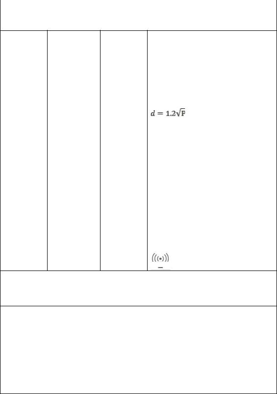
Portable and mobile RF communications equipment should be used no closer to any part of the Ultrasound System, including cables, than the recommended separation distance. This is calculated using the equation applicable to the frequency of the transmitter.
Recommended separation distance
 80MHz to 800MHz
  800MHz to 2.5GHz
Where P is the transmitter’s maximum output power rating in watts (W) according to the transmitter’s manufacturer, and d is the recommended separation distance in meters
(m).
Field strengths from fixed RF transmitters, as determined by an electromagnetic site survey, ashould be less than the compliance level in each frequency range.b
Interference may occur in the vicinity of equipment marked with the following symbol:
Note 1) At 80MHz and 800MHz, the higher frequency range applies.
Note 2) These guidelines may not apply in all situations. Electromagnetic propagation is affected by absorption and reflection from structures, objects and people.
aField strengths from fixed transmitters, such as base stations for radio, (cellular/cordless) telephones and land mobile radios, amateur radio, AM and FM radio broadcasts and TV broadcasts cannot be predicted with accuracy. To assess the electromagnetic environment due to fixed RF transmitters, an electromagnetic site survey should be considered. If the measured field strength, in the location in which the Ultrasound System is used, exceeds the applicable RF compliance level above, the Ultrasound System should be observed to verify normal operation. If abnormal performance is observed, additional measures may be necessary, such as reorienting or relocating the Ultrasound System or using a shielded location with a higher RF shielding effectiveness and filter attenuation.
bIOver the frequency range 150kHz to 80MHz, field strengths should be less than 3 V/m.

1 - 16 HS70A Service Manual
▐ Recommended Separation Distances between This Product and RF Communications Equipment
This product is intended for use in an electromagnetic environment in which radiated RF disturbances are controlled. The customer or the user of this product can help prevent electromagnetic interference by maintaining a minimum distance between portable and mobile RF communications equipment (transmitters) and this product. These distances are recommended below, according to the maximum output power of the communications equipment.
Rated maximum |
Separation distance, according to frequency of transmitter m |
|||
|
|
|
||
output power of |
|
|
|
|
150kHz ~ 80MHz |
80MHz ~ 800MHz |
800MHz ~ 2.5GHz |
||
transmitter |
||||
W |
|
|
|
|
|
|
|
|
|
0.01 |
0.12 |
0.12 |
0.23 |
|
0.1 |
0.38 |
0.38 |
0.73 |
|
|
|
|
||
|
|
|
|
|
1 |
1.2 |
1.2 |
2.3 |
|
|
|
|
||
|
|
|
|
|
10 |
3.8 |
3.8 |
7.3 |
|
|
|
|
||
|
|
|
|
|
100 |
12 |
12 |
23 |
|
For transmitters rated at a maximum output power not listed above, the recommended separation distance d in meters (m) can be estimated using the equation applicable to the frequency of the transmitter, where p is the maximum output power rating of the transmitter in watts (W), according to the transmitter’s manufacturer.
NOTE 1) At 80MHz and 800MHz, the separation distance for the higher frequency range applies. NOTE 2) These guidelines may not apply in all situations. Electromagnetic propagation is affected by absorption and reflection from structures, objects and people.
 Loading...