


 Loading...
DIGITAL HOME
CINEMA SYSTEM
HT-Q20
HT-TQ22
HT-TQ25
Instruction Manual
VOLUME
OPEN/CLOSE
FUNCTION
STANDBY
COMPACT
DIGITAL AUDIO

 Safety Warnings
CLASS 1 LASER PRODUCT KLASSE 1 LASER PRODUKT LUOKAN 1 LASER LAITE KLASS 1 LASER APPARAT PRODUCTO LASER CLASE 1
Use of controls, adjustments or performance of procedures other than those specified herein may result in hazardous radiation exposure.
CAUTION-INVISIBLE LASER RADIATION WHEN OPEN AND INTERLOCKS DEFEATED, AVOID EXPOSURE TO BEAM.
CAUTION
RISK OF ELECTRIC SHOCK.
DO NOT OPEN
CAUTION:
TO REDUCE THE RISK OF ELECTRIC SHOCK, DO NOT REMOVE REAR COVER. NO USER SERVICEABLE PARTS INSIDE. REFER SERVICING TO QUALIFIED SERVICE PERSONNEL.
CLASS 1 LASER PRODUCT
This symbol indicates that dangerous voltage which can cause electric shock is present inside this unit.
This symbol alerts you to important operating and maintenance instructions accompanying the unit.
WARNING: To reduce the risk of fire or electric shock, do not expose this appliance to rain or moisture.
CAUTION: TO PREVENT ELECTRIC SHOCK, MATCH WIDE BLADE OF PLUG TO WIDE SLOT, FULLY INSERT.
This Compact Disc player is classified as a CLASS 1 LASER product.
ïThis apparatus shall always be connected to a AC outlet with a protective grounding connection.
ïTo disconnect the apparatus from the mains, the plug must be pulled out from the mains socket, therefore the mains plug shall be readily operable.
Plug(UK Only)
moulded plug incorporating a fuse. The value of the fuse is indicated on the pin approved to BS1362 of the same rating must be used.
cover is detachable and a replacement is required, it must be of the same are available from your dealer.
your house or the cable is not long enough to reach a power point, you lead or consult your dealer for assistance.
remove the fuse and then safely dispose of the plug. Do not connect the from the bared flexible cord.
main socket. A plug and fuse must be used at all times.
IMPORTANT
accordance with the following code:ñ
NEUTRAL BROWN = LIVE
coloured markings identifying the terminals in your plug, proceed as fol-
the terminal marked with the letter N or coloured BLUE or BLACK. to the terminal marked with the letter L or coloured BROWN or RED.
WIRE TO THE EARTH TERMINAL WHICH IS MARKED WITH
EARTH SYMBOL  , OR COLOURED GREEN OR GREEN
1

 Precautions
GB
PREPARATION
Ensure that the AC power supply in your house complies with the identification sticker located on the back of your player. Install your player horizontally, on a suitable base (furniture), with enough space around it for ventilation (3~4inches). Make sure the ventilation slots are not covered. Do not stack anything on top of the player. Do not place the player on amplifiers or other equipment which may become hot. Before moving the player, ensure the disc tray is empty. This player is designed for continuous use. Switching off the DVD player to the stand-by mode does not disconnect the electrical supply. In order to disconnect the player completely from the power supply, remove the main plug from the wall outlet, especially when left unused for a long period of time.
During thunderstorms, disconnect AC main plug from the wall outlet.
Voltage peaks due to lightning could damage the unit.
Protect the player from moisture(i.e. vases) , and excess heat
(e.g.fireplace) or equipment creating strong magnetic or electric fields (i.e.speakers...). Disconnect the power cable from the AC supply if the player malfunctions. Your player is not intended for industrial use.
Use of this product is for personal use only.
Condensation may occur if your player or disc has been stored in cold temperatures.
If transporting the player during the winter, wait approximately 2 hours until the unit has reached room temperature before using.
Do not expose the unit to direct sunlight or other heat sources.
This could lead to overheating and malfunction of the unit.
The batteries used with this product contain chemicals that are harmful to the environment.
Do not dispose of batteries in the general household trash.
2

 Features
 Multi-Disc Playback & FM Tuner
The HT-Q20/HT-TQ22/HT-TQ25 combines the convenience of multi-disc playback capability, including DVD-VIDEO, VCD, CD, MP3-CD, WMA-CD, DivX, CD-R/RW, and DVD-R/RW, with a sophisticated FM tuner, all in a single player.
 USB HOST Function support
You can connect and play files from external USB storage devices such as
MP3 players, USB flash memory, etc. using the Home Theater's USB HOST function.
 Dolby Pro Logic II
Dolby Pro Logic II is a new form of multi-channel audio signal decoding technology that improves upon existing Dolby Pro Logic.
 DTS (Digital Theater Systems)
DTS is an audio compression format developed by Digital Theater
Systems Inc. It delivers full-frequency 5.1 channel sound.
 TV Screen Saver Function
The HT-Q20/HT-TQ22/HT-TQ25 automatically brightens and darkens your TV screen after 3 minutes in the stop mode.
The HT-Q20/HT-TQ22/HT-TQ25 automatically switches itself into the power saving mode after 20 minutes in the screen saver mode.
 Power Saving Function
The HT-Q20/HT-TQ22/HT-TQ25 automatically shuts itself off after 20 minutes in stop mode.
 Customized TV Screen Display
The HT-Q20/HT-TQ22/HT-TQ25 allows you to select your favorite image during JPEG, DVD or VCD playback and set it as your background wallpaper.
 Optional Wireless receiver amplifier
Samsung ís optional rear-channel wireless module does away with cables running between your DVD receiver and rear-channel speakers. Instead,the rear speakers connect to a compact wireless module that communicates with your DVD receiver.
3

 Contents
GB
 PREPARATION
Safety Warnings . . . . . . . . . . . . . . . . . . . . . . . . . . . .1 Precautions . . . . . . . . . . . . . . . . . . . . . . . . . . . . . . .2
Features . . . . . . . . . . . . . . . . . . . . . . . . . . . . . . . . . .3
Notes on Discs . . . . . . . . . . . . . . . . . . . . . . . . . . . . .5 Description . . . . . . . . . . . . . . . . . . . . . . . . . . . . . . . .7
 CONNECTIONS
Connecting the Speakers . . . . . . . . . . . . . . . . . . . .11
Connecting the optional Wireless Receiving Amplifier 14
Connecting the Video Out to TV . . . . . . . . . . . . . . .16 P.SCAN(Progressive Scan) Function . . . . . . . . . . . .17 Connecting External Components . . . . . . . . . . . . . .18 Connecting the FM Antenna . . . . . . . . . . . . . . . . . .19
 OPERATION
Before Using Your Home Theater . . . . . . . . . . . . . .20 Disc Playback . . . . . . . . . . . . . . . . . . . . . . . . . . . . .22
MP3/WMA-CD Playback . . . . . . . . . . . . . . . . . . . . .23 Displaying Disc Information . . . . . . . . . . . . . . . . . . .24 JPEG File Playback . . . . . . . . . . . . . . . . . . . . . . . .25
DivX Playback . . . . . . . . . . . . . . . . . . . . . . . . . . . .27 Checking the Remaining Time . . . . . . . . . . . . . . . .29
Fast/Slow Playback . . . . . . . . . . . . . . . . . . . . . . . .30 Skipping Scenes/Songs . . . . . . . . . . . . . . . . . . . . .30 Repeat Playback . . . . . . . . . . . . . . . . . . . . . . . . . .31
A-B Repeat Playback . . . . . . . . . . . . . . . . . . . . . . .32 Step Function . . . . . . . . . . . . . . . . . . . . . . . . . . . . .33
Angle Function . . . . . . . . . . . . . . . . . . . . . . . . . . . .33 Zoom (Screen Enlarge) Function . . . . . . . . . . . . . .34 EZ VIEW Function . . . . . . . . . . . . . . . . . . . . . . . . .34
Selecting Audio Language . . . . . . . . . . . . . . . . . . .35 Selecting Subtitle Language . . . . . . . . . . . . . . . . . .36
Playing Media Files using the USB HOST feature . .37 Moving Directly to a Scene/Song . . . . . . . . . . . . . .39 Using Disc Menu . . . . . . . . . . . . . . . . . . . . . . . . . .40
Using the Title Menu . . . . . . . . . . . . . . . . . . . . . . . .40
 SETUP
SETUP
Setting the Language . . . . . . . . . . . . . . . . . . . . . . .41 Setting TV Screen type . . . . . . . . . . . . . . . . . . . . . .43
Setting Parental Controls (Rating Level) . . . . . . . . .45
Setting the Password . . . . . . . . . . . . . . . . . . . . . . .46 Setting the Wallpaper . . . . . . . . . . . . . . . . . . . . . . .47 DivX (R) registration . . . . . . . . . . . . . . . . . . . . . . . .49 Setting the Speaker Mode . . . . . . . . . . . . . . . . . . .50
Setting the Delay Time . . . . . . . . . . . . . . . . . . . . . .51
Setting the Test Tone . . . . . . . . . . . . . . . . . . . . . . .53 Setting the DRC (Dynamic Range Compression) . .54 Setting the Audio Quality . . . . . . . . . . . . . . . . . . . . .55 AV SYNC Setup . . . . . . . . . . . . . . . . . . . . . . . . . . .57 Sound Field (DSP)/EQ Function . . . . . . . . . . . . . . .58
Dolby Pro Logic II Mode . . . . . . . . . . . . . . . . . . . . .59 Dolby Pro Logic II Effect . . . . . . . . . . . . . . . . . . . . .60
 RADIO OPERATION
Listening to Radio . . . . . . . . . . . . . . . . . . . . . . . . . .61 Presetting Stations . . . . . . . . . . . . . . . . . . . . . . . . .62
About RDS broadcasting . . . . . . . . . . . . . . . . . . . .63
 MISCELLANEOUS
Convenient Functions . . . . . . . . . . . . . . . . . . . . . . .65 Operating a TV with the Remote Control . . . . . . . . .67 Before Calling for Service . . . . . . . . . . . . . . . . . . . .68
Cautions on Handling and Storing Discs . . . . . . . . .71 Language Code List . . . . . . . . . . . . . . . . . . . . . . . .72
USB Host Feature Supported Products . . . . . . . . . .73 Specifications . . . . . . . . . . . . . . . . . . . . . . . . . . . . .74
PREPARATION
4
 Notes on Discs
DVD (Digital Versatile Disc) offers fantastic audio and video, thanks to Dolby Digital surround sound and MPEG-2 video compression technology. Now you can enjoy these realistic effects in the home, as if you were in a movie theater or concert hall.
1 ~ |
6 |
DVD players and the discs are coded by region. These regional codes must match in order |
|
for the disc to play. If the codes do not match, the disc will not play.
The Region Number for this player is given on the rear panel of the player.
(Your DVD player will only play DVDs that are labeled with identical region codes.)
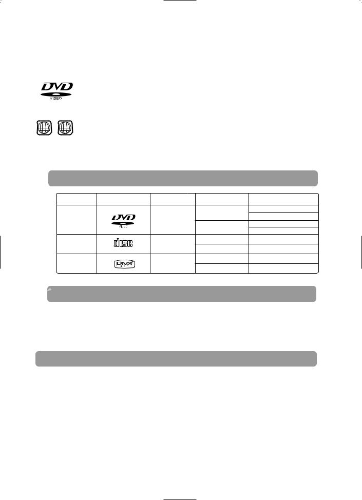
 Playable Discs
|
|
|
12cm |
Approx. 240 min. (single-sided) |
|
|
|
Approx. 480 min. (double-sided) |
|
DVD-VIDEO |
|
Video |
|
|
|
|
Approx. 80 min. (single-sided) |
||
|
|
|
8cm |
|
|
|
|
Approx. 160 min. (double-sided) |
|
|
|
|
|
|
AUDIO-CD |
COMPACT |
Audio |
12cm |
74 min. |
VIDEO-CD |
DIGITAL AUDIO |
Audio + Video |
8cm |
20 min. |
|
|
|
|
|
Divx |
|
MPEG4 |
12cm |
74 min. |
|
MP3 |
8cm |
20 min. |
|
|
|
 Do not use the following types of disc!
Copy Protection
5

Disc Recording Format
 This product does not support Secure (DRM) Media files.
GB
the |
PREPARATION |
|
you may
(. / = +).
disc,
.
(. / = +). disc,
by the
6
 Description
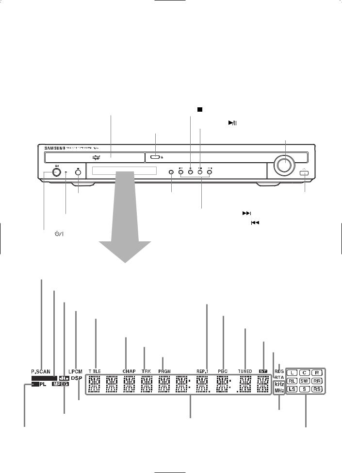
—Front Panel—
|
Disc Tray |
Stop ( ) button |
|
|
|
Play/Pause ( ) button |
|
|
|
Open/Close button |
Volume buttons |
|
|
|
|
|
|
|
VOLUME |
|
|
OPEN/CLOSE |
|
|
|
FUNCTION |
|
|
STANDBY |
|
|
|
Remote |
Function button |
USB Connector |
|
Control Sensor |
|
|
|
Standby indicator |
Tuning Up & Skip ( |
) buttons |
|
Tuning Down & Skip ( |
) buttons |
|
|
|
||
Power ( |
) button |
|
|
P.SCAN indicator |
|
|
|
|
|
|
|
|
|
|
|
|
|
|
|
|
|
|
||||||||||
|
|
|
|
|
|
|
|
|
|
|
|
|
|
|
|
|
|
|
|
|
|
|
|
|
|
|
|
|
|
|
DOLBY DIGITAL indicator |
|
|
|
|
|
|
|
|
|
|
|
|
|
|
|
|
|
|||||||||
|
|
|
|
|
|
|
|
|
|
|
|
|
|
|
|
|
|
|
|
|
|
|
|
|||||
|
|
|
|
|
DTS Disc indicator |
|
|
|
|
|
|
|
|
|
|
|
|
|
|
|
|
|||||||
|
|
|
|
|
|
|
|
|
|
|
REPEAT indicator |
|
|
|
|
|
|
|
|
|
|
|||||||
|
|
|
|
|
|
|
|
|
|
|
|
|
|
|
|
|
|
|||||||||||
|
|
|
|
|
|
|
|
|
|
|
|
|
|
|
|
|
||||||||||||
|
|
|
|
|
|
LINEAR PCM indicator |
|
|
|
|
|
|
|
|
|
|
|
|
|
|||||||||
|
|
|
|
|
|
|
|
|
|
|
|
|
|
|
|
|
|
|
|
|||||||||
|
|
|
|
|
|
|
|
|
|
|
|
|
|
|
|
|
|
PBC indicator |
|
|||||||||
|
|
|
|
|
|
|
|
|
|
|
|
|
|
|
|
|
|
|||||||||||
|
|
|
|
|
|
|
|
TITLE indicator |
|
|
|
|
|
|||||||||||||||
|
|
|
|
|
|
|
|
|
|
|
|
|
|
|
|
|
|
|
|
|
|
|
|
|||||
|
|
|
|
|
|
|
|
|
|
|
|
|
|
|
|
|
|
|
|
|
|
|
|
|
|
|
||
|
|
|
|
|
|
|
|
|
|
|
|
|
|
|
|
|
|
|
|
TUNER indicator |
||||||||
|
|
|
|
|
|
|
|
|
|
|
|
|
|
|
|
|
|
|
|
|
|
|
|
|
|
|
|
|
|
|
|
|
|
|
|
|
|
|
CHAPTER indicator |
|
|
|
|
|
|
|
|
|
|
|
|
||||||
|
|
|
|
|
|
|
|
|
|
|
|
STEREO indicator |
|
|
|
|||||||||||||
|
|
|
|
|
|
|
|
|
|
|
|
|
|
|
|
|
|
|
|
|
|
|
|
|||||
|
|
|
|
|
|
|
|
|
|
|
|
|
TRACK indicator |
|
|
|
|
|
|
|||||||||
|
|
|
|
|
|
|
|
|
|
|
|
|
|
|
|
|
|
|
|
|
|
|
|
|||||
|
|
|
|
|
|
|
|
|
|
|
|
|
|
|
|
|
|
RTA indicator |
|
|
||||||||
|
|
|
|
|
|
|
|
|
|
|
|
|
|
|
PROGRAM indicator |
|
|
|
|
|
|
|||||||
|
|
|
|
|
|
|
|
|
|
|
|
|
|
|
|
|
|
|
|
|
|
|
|
|
|
|||
|
|
|
|
|
|
|
|
|
|
|
|
|
|
|
|
|
|
|
|
|
|
|
|
RDS indicator |
|
|||
|
|
|
|
|
|
|
|
|
|
|
|
|
|
|
|
|
|
|
|
|
|
|
|
|
|
|
|
|
|
|
|
|
|
|
|
|
|
|
|
|
|
|
|
|
|
|
|
|
|
|
|
|
|
|
|
|
|
|
|
|
|
|
|
|
|
|
|
|
|
|
|
|
|
|
|
|
|
|
|
|
|
|
|
|
|
|
|
|
|
|
|
|
|
|
|
|
|
|
|
|
|
|
|
|
|
|
|
|
|
|
|
|
|
|
|
|
|
|
|
|
|
|
|
|
|
|
|
|
|
|
|
|
|
|
|
|
|
|
|
|
|
|
|
|
|
|
|
|
|
|
|
|
|
|
|
|
|
|
|
|
|
|
|
|
|
|
|
|
|
|
|
|
|
|
|
|
|
|
|
|
|
|
|
|
|
|
|
|
|
|
|
|
|
|
|
|
|
|
|
|
|
|
DSP indicator |
|
|
|
MPEG indicator |
|
RADIO FREQUENCY |
|
System Status Display |
indicator |
||
|
|||
PRO LOGIC indicator |
|
SPEAKER indicator |
7
GB
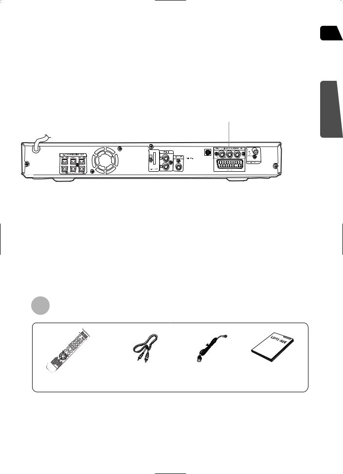
—Rear Panel—
Video Output Connector
Connect the TV's video input jacks (VIDEO IN) to the VIDEO OUT connector.
COMPONENT VIDEO OUTPUT jacks
Connect a TV with component video inputs to these jacks.
FM Antenna Connector
PREPARATION
|
|
|
|
|
|
|
|
|
|
|
|
|
|
|
|
|
|
|
|
|
|
|
|
|
|
|
|
|
|
|
|
|
|
|
|
|
|
|
|
|
|
|
|
|
|
|
|
|
|
|
|
|
|
|
|
|
|
|
|
|
|
|
|
|
|
|
|
|
|
|
|
|
|
|
|
|
|
|
|
|
|
|
|
|
|
|
|
|
|
|
|
|
|
|
|
|
|
|
|
|
|
|
|
|
|
|
|
|
|
|
|
|
|
|
|
|
|
|
|
|
|
|
|
|
|
|
|
|
|
|
|
|
|
|
|
|
|
|
|
|
|
|
|
|
|
|
|
|
|
|
|
|
|
|
|
|
|
|
|
|
|
|
|
|
|
|
|
|
|
|
|
|
|
|
|
|
Cooling |
|
Fan |
|
|
External Audio Input |
|
|
|
|
|||||||||||||
|
|
|
|
|
Connector |
|
SCART JACK |
|||||||||||||||||
|
|
|
|
|
|
|
|
|
|
|
|
|
|
|
|
|
|
|
|
|
|
Connect to a TV with scart input jack. |
||
|
|
|
|
|
|
|
|
|
|
|
|
|
|
|
|
|
|
|
|
|
|
|||
|
|
|
|
|
|
|
|
|
|
|
|
|
|
|
|
|
|
|
|
|
|
|
|
|
5.1 Channel Speaker |
|
|
|
|
|
|
|
|
|
|
|
|
|
|
|
|
|
|
|
|||||
|
|
|
|
|
|
|
|
|
|
|
|
|
|
|
|
|
|
|
|
|||||
Output Terminals |
|
TX Card Connector |
|
|
|
|
|
|
||||||||||||||||
|
|
|
|
|
|
|
|
|
|
|
|
|
|
|
|
|
|
|
|
|
|
|
|
|
|
|
|
|
|
|
|
|
|
|
|
|
|
|
|
|
|
|
|
|
|
|
|
|
|
Accessories
Remote Control |
Video Cable |
FM Antenna |
User's Manual |
 Description
—Remote Control—
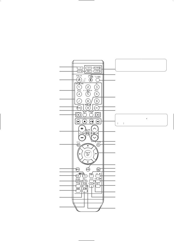
TV button
DVD RECEIVER button
POWER button
RDS Selection button
Number(0~9) buttons
REMAIN button
STEP button
SEARCH buttons
VOLUME button
MENU button
INFO button 
 PL II EFFECT button

 PL II MODE button TUNER MEMORY, P.SCAN button
ZOOM button
SLEEP button
SLOW, MO/ST button
DIMMER button
 DVD button
  TUNER
TUNER  AUX button
  USB button
OPEN/CLOSE button
TV/VIDEO button
VIDEO.SEL button
CANCEL button
REPEAT button
 Play/Pause button
  Stop button
 Tuning Preset/CD Skip button
TUNING/CH button
MUTE button
RETURN button
Cursor/Enter button
AUDIO button
SUB TITLE button
DSP/EQ button
TEST TONE button
SOUND EDIT button
DIGEST button
LOGO button
SLIDE MODE button
EZ VIEW, NT/PAL button
9
Insert Remote Batteries
1 Remove the battery cover on the back of the remote by pressing down and sliding the cover in the direction of the arrow.
2 Insert two 1.5V AAA |
3 Replace the battery |
batteries, paying |
cover. |
attention to the correct |
|
polarities (+ and ñ). |
|
|
|
GB
PREPARATION
Caution |
Follow these precautions to avoid leaking or cracking cells: |
ï Place batteries in the remote control so they match the polarity:(+) to (+)and (ñ)to (ñ). |
ïUse the correct type of batteries.Batteries that look similar may differ in voltage.
ïAlways replace both batteries at the same time.
ïDo not expose batteries to heat or flame.
Range of Operation of the Remote Control
The remote control can be used up to approximately 23 feet/7 meters in a straight line. It can also be operated at a horizontal angle of up to 30° from the remote control sensor.
10
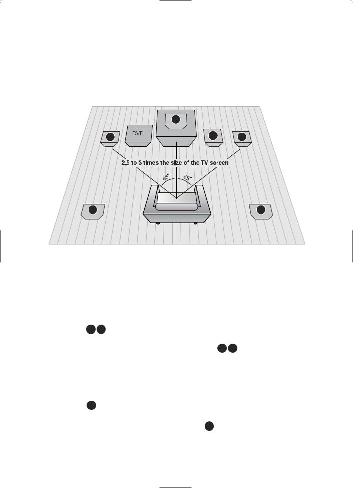
 Connecting the Speakers
Before moving or installing the product, be sure to turn off the power and disconnect the power cord.
|
C |
|
L |
SW |
R |
SL |
SR |
Position of the DVD Player
ïPlace it on a stand or cabinet shelf, or under the TV stand.
Front Speakers L R
ïPlace these speakers in front of your listening position, facing inwards (about 45°) toward you.
ïPlace the speakers so that their tweeters will be at the same height as your ear.
ïAlign the front face of the front speakers with the front face of the center speaker or place them slightly in front of the center speakers.
Center Speaker C
ïIt is best to install it at the same height as the front speakers.
ïYou can also install it directly over or under the TV.
Selecting the Listening Position
The listening position should be located about 2.5 to 3 times the distance of the TV's screen size away from the TV. Example: For 32" TVs 2~2.4m (6~8feet)
For 55" TVs 3.5~4m (11~13feet)
Rear Speakers SL SR
ïPlace these speakers behind your listening position.
ïIf there isn't enough room, place these speakers so they face each other.
ïPlace them about 60 to 90cm (2 to 3feet) above your ear, facing slightly downward.
* Unlike the front and center speakers, the rear speakers are used to handle mainly sound effects and sound will not come from them all the time.
Subwoofer SW
ïThe position of the subwoofer is not so critical. Place it anywhere you like.
11

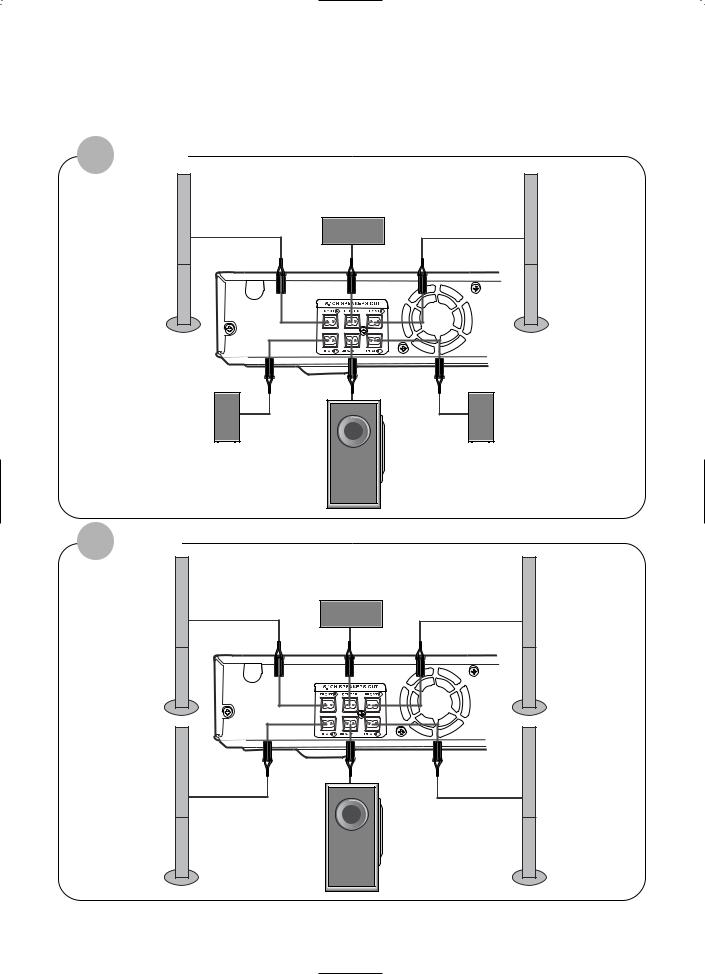
GB
HT-Q20
Center Speaker
Front Speaker (R) |
Front Speaker (L) |
CONNECTIONS
Rear Speaker (R) |
Rear Speaker (L) |
Subwoofer
Connecting the Speakers
1 Press down the terminal tab on the back of the speaker.
2 Insert the black wire into the |
3 Connect the correct color speaker cable |
||||||||||
black terminal (ñ) and the red |
to the same color speaker output terminal |
||||||||||
wire into the red (+) terminal, |
on the rear of the subwoofer, according |
||||||||||
and then release the tab. |
to the polarity markings (+/ñ). |
||||||||||
|
|
|
|
|
|
|
|
|
|
|
Example: Connect the green center speaker cable |
Black |
|
|
|
|
|
|
|
|
|
Red |
to the green center speaker output |
|
|
|
|
|
|
|
|
|
terminal on the rear of the subwoofer |
||
|
|
|
|
|
|
|
|
|
|
|
|
|
|
|
|
|
|
|
|
|
|
|
|
|
|
|
|
|
|
|
|
|
|
|
according to the polarity markings (+/ñ). |
|
|
|
|
|
|
|
|
|
|
|
|
|
|
|
|
|
|
|
|
|
|
|
|
Caution |
ïDo not let children play with or near the speakers. They could get hurt if a speaker falls.
ïWhen connecting the speaker wires to the speakers, make sure that the polarity (+/ñ) is correct.
Note |
ïIf you place a speaker near your TV set, screen color may be distorted because of the magnetic field generated by the speaker. If this occurs, place the speaker away from your TV set.
12
 Connecting the Speakers
HT-TQ22
|
Center Speaker |
(R) |
Front Speaker (L) |
Rear Speaker (R) |
Rear Speaker (L) |
Subwoofer
HT-TQ25
Center Speaker
(R) |
Front Speaker (L) |
(R) |
Rear Speaker (L) |
Subwoofer
13
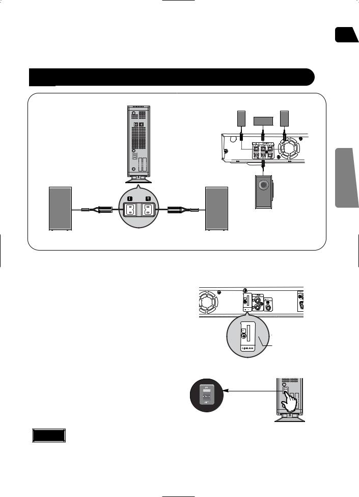
 Connecting the optional Wireless ReceivingAmplifier GB
To connect the rear speakers wirelessly, you have to additionally purchase the wireless receiving module and TX card from your Samsung retailer.
When you have purchased the wireless receiving module (SWA-3000)
Front Speaker (R) |
Front Speaker (L) |
Center Speaker
CONNECTIONS
Subwoofer
Rear Speaker (L) |
WIRELESS RECEIVER MODULE |
Rear Speaker (R) |
|
1 |
Connect the front, center and |
|
|
|
subwoofer speakers, referring to page 12. |
|
|
2 |
Insert the TX card into the TX card |
|
|
|
connection port on the back of the main unit. |
|
|
|
ï Hold the TX card so that the slanted side faces |
|
|
|
downward and insert the card into the port. |
|
|
|
ï The TX card enables communication between the |
|
|
|
main unit and the wireless receiver. |
|
|
3 |
Connect the left and right rear |
|
|
|
speakers to the wireless receiving |
|
|
|
module. |
|
|
4 |
Plug the power cord of the wireless |
|
|
|
|
||
|
|
||
|
receiving module in the wall outlet and |
|
|
|
|
||
switch the power switch ëONí.

 TX card
Slanted side faces
Caution |
ïDo not insert a card other than the TX card dedicated for the product. The product might be damaged or it may not be removed easily.
ïDo not insert the TX card upside down or in reverse direction.
ïInsert the TX card when the main unit is turned off.Inserting the card when it is turned on may cause a problem. 14
 Connecting the optional Wireless Receiving Amplifier

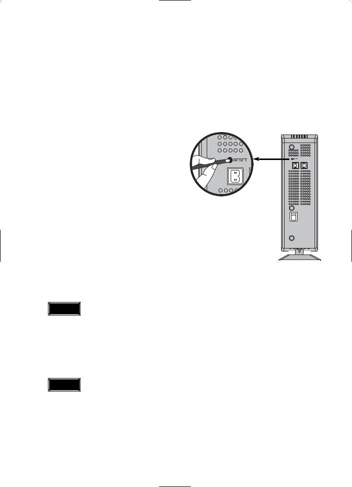
 Resetting Wireless Communication
Reset the system if a communication failure occurs, or if the Link indicator (blue LED) on the wireless receiver does not light up and the "REAR CHK" message blinks on the main unit's display.
Reset the system while the main unit and the wireless receiver module (SWA-3000) are in Power Standby mode.
1 With the main unit turned off, press and hold the remote control's REMAIN button for 5 seconds.
ï Press the button until the POWER(  ) indicator lights up blue. (The indicator will turn off in 1 second.)
2 With the wireless receiver module
|
turned on, use a ball point pen or a pair |
|
|
|
|
|
|
|
|
|
|
|
of tweezers to press the RESET button |
WIRELESS RECEIVER MODULE |
|
|
|
|
|
|
|
||
|
on the back of the unit. |
|
|
|
|
|
|
|
|
|
|
|
ï The Standby/On LED on the front panel of the |
|
|
|
|
|
|
|
|
|
|
3 |
wireless receiver module blinks 2 times. |
|
|
|
|
|
|
|
|
|
|
|
|
|
|
|
|
|
|
|
|
||
Turn on the main unit. |
|
|
|
|
|
|
|
|
|
|
|
|
|
|
|
|
|
|
|
|
|
||
|
|
|
|
|
|
|
|
|
|
||
|
|
|
|
|
|
|
|
|
|
||
|
|
|
|
|
|
|
|
|
|
||
|
ï The Link LED of the wireless receiver module is lit |
|
|
|
|
|
|
|
|
|
|
and the setup is finished.
ï If Power Standby mode continues, repeat Steps 1 to 3 above.
Caution |
ïWhen the wireless receiving module setting is complete, no audio signal is output from the Rear Speaker OUT ports on the back of the main unit.
ïThe wireless receiving antenna is built into the wireless receiver module. Keep the unit away from water and moisture.
ïFor optimal listening performance, make sure that the area around the wireless receiver module location is clear of any obstructions.
ïSound will be heard from the wireless rear speakers in DVD 5.1-CH or Dolby Pro Logic II mode only.
ïIn 2-CH mode, no sound will be heard from the wireless rear speakers.
Note |
ïPlace the wireless receiver module at the rear of the listening position. If the wireless receiver module is too close to the main unit, some sound interruption may be heard due to interference.
ïIf you use a device such as a microwave oven, wireless LAN Card, Bluetooth equipment, or any other device that uses the same frequency (2.4GHz) near the system, some sound interruption may be heard due to interference.
ïThe transmission distance of radio wave is about 33 feet, but may vary depending on your operating environment.
If a steel-concrete wall or metallic wall is between the main unit and the wireless receiver module, the system may not operate at all, because the radio wave cannot penetrate metal.
15
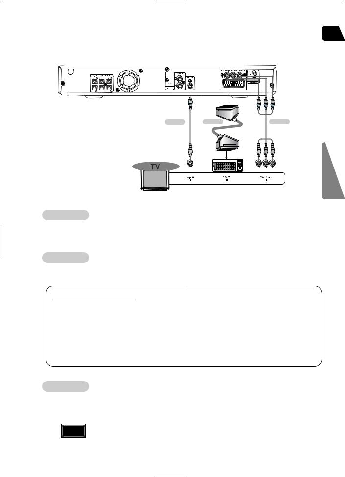
 Connecting the Video Out to TV
GB
Choose one of the three methods for connecting to a TV.
METHOD 1 |
METHOD 2 |
CONNECTIONS
METHOD 1 |
Composite Video |
Good Quality |
Connect the supplied video cable from |
OUT jack on the back panel of the |
|
system to the VIDEO IN jack on your |
|
|
METHOD 2 |
Scart ............... Better |
|
If you television is equipped with an AV OUT jack on the back panel of the
connect an Scart Jack (not supplied) from the the SCART IN jack on your television.
VIDEO SELECT Function |
|
Press and hold VIDEO SEL. |
the remote control for over 5 seconds. |
ï "COMPOSITE" or "RGB" will appear in |
. |
At this time, press the VIDEO SEL. |
to select between "COMPOSITE" and "RGB". |
ï If Scart (RGB Input) is equipped for your |
VIDEO SEL. button to select RGB mode. |
You can get a better picture quality by |
setting. |
ï If Scart (RGB Input) is not equipped for |
press VIDEO SEL. button to select COMPOSITE |
mode. |
|
METHOD 3 Component (Progressive Scan) Video ............... Best Quality
If your television is equipped with Component Video inputs, connect a component video cable (not supplied) from the Pr, Pb and Y jacks on the back panel of the system to the corresponding jacks on your television.
Note ï When the Progressive scan mode is selected, the VIDEO output (Yellow) and SCART output does not output any signal.
16
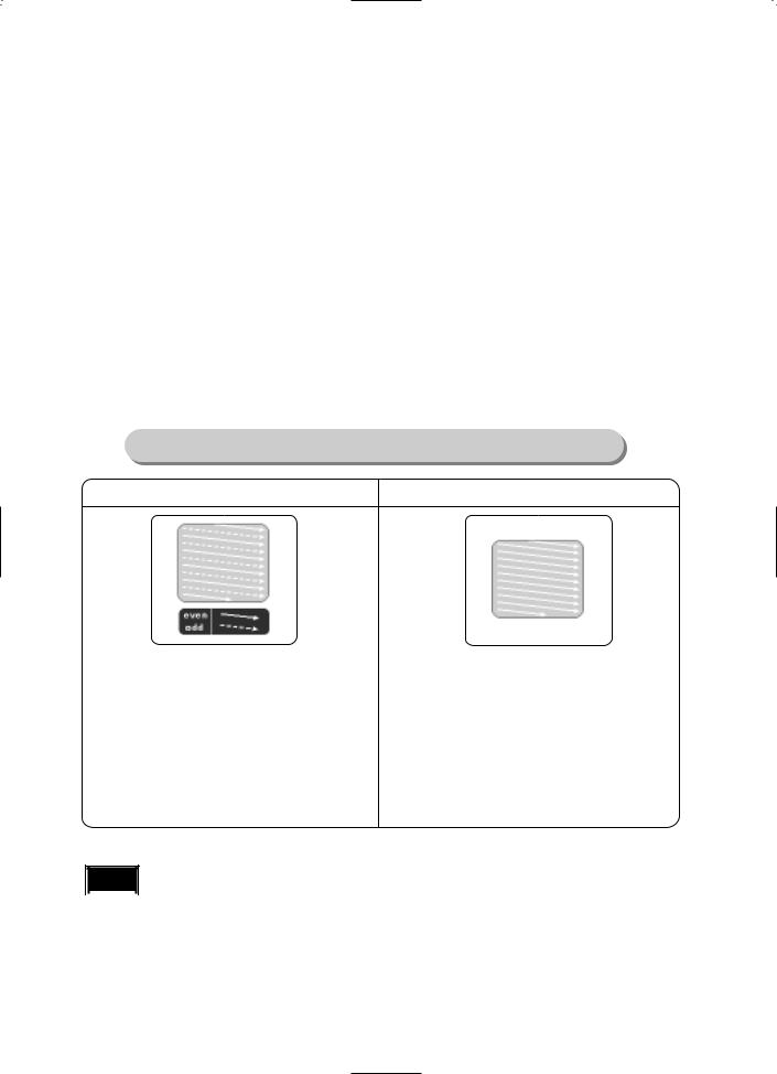
 P.SCAN(Progressive Scan) Function
Unlike regular Interlace Scan, in which two fields of picture information alternate to create the entire picture (odd scan lines, then even scan lines), Progressive Scan uses one field of information (all lines displayed in one pass) to create a clear and detailed picture without visible scan lines.
1
2
Press STOP button.
ï If playing a disc, press the STOP button twice so that ìSTOPî, appears on the display.
Press and hold P.SCAN button on the remote control for over 5 seconds.
ïPressing and holding the button for over 5 seconds will select "Progressive Scan" and "Interlace Scan" alternately.
ïWhen you select P.SCAN, "P.SCAN" will appear on the display.
ïTo set P.Scan mode for DivX discs, press the P.SCAN button on the remote control for more than 5 seconds with no disc in the unit (ì'NO DISC" on the display), then load the DivX disc and play.
What is Progressive (or Non-Interlaced) Scanning?
In interlaced-scan video, a frame consists of two interlaced fields (odd and even), where each field contains every other horizontal line in the frame.
The odd field of alternating lines is displayed first, and then the even field is displayed to fill in the alternating gaps left by the odd field to form a single frame.
One frame, displayed every 1/30th of a second, contains two interfaced fields, thus a total of 60 fields are displayed every 1/60th of a second.
The interlaced scanning method is intended for capturing a still object.
The progressive scanning method scans one full frame of video consecutively down the screen, line by line.
An entire image is drawn at one time, as opposed to the interlaced scanning process by which a video image is drawn in a series of passes.
The progressive scanning method is desirable for dealing with moving objects.
Note ï This function works only on TVs equipped with component video inputs (Y, Pr, Pb) that support  Progressive Video. (It does not work on TVs with conventional component inputs, i.e., non-progressive
scan TVs.)
ï Depending on the capabilities of your TV, this function may not work.
17
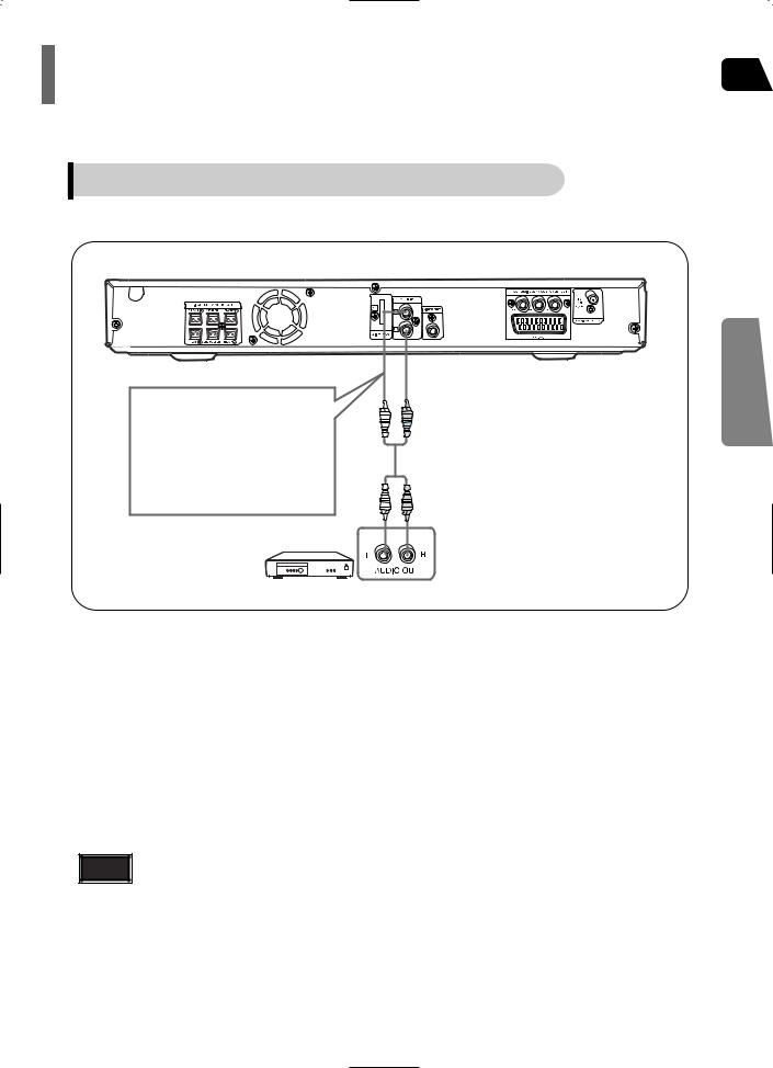
Connecting External Components |
GB |
|
Connecting an External Analog Component
Example: Analog signal components such as a VCR.
Audio Cable
(not supplied)
If the external analog component has only one Audio Out, connect either left or right.
1 Connect AUX (Audio) In on the Home Theater to Audio Out on the external analog component.
ï Be sure to match connector colors.
2 Press AUX button on the remote control to select ëAUXí input.
ï You can also use the FUNCTION button on the main unit.
The mode switches as follows: DVD/CD AUX USB FM
Note |
ï You can connect the Video Output jack on your VCR to the TV, and connect the Audio |
|
Output jacks on the VCR to this product. |
CONNECTIONS
18
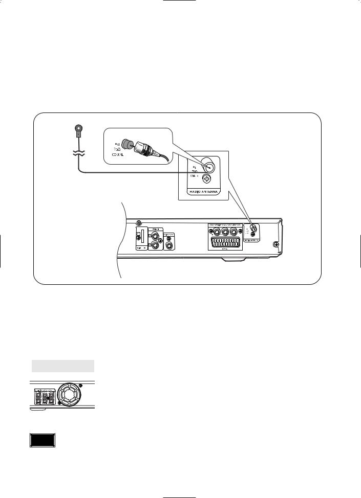
 Connecting the FM Antenna
FM Antenna (supplied)
1 Connect the FM antenna supplied to the FM 75Ω COAXIAL terminal.
2 Slowly move the antenna wire around until you find a location where reception is good, then fasten it to a wall or other rigid surface.
Cooling Fan |
The cooling fan supplies cool air to the unit to prevent overheating. |
Please observe the following cautions for your safety.
ï Make sure the unit is well-ventilated. If the unit has poor ventilation, the temperature inside the unit could rise and may damage it.
ï Do not obstruct the cooling fan or ventilation holes. (If the cooling fan or ventilation holes are covered with a newspaper or cloth, heat may build up inside the unit and fire may result.)
Note |
ï This unit does not receive AM broadcasts. |
19
 Before Using Your Home Theater
Your Home Theater is capable of playing DVD, CD, MP3/WMA and JPEG discs.Depending on the disc you are using, these instructions may vary slightly. Read the instructions carefully before using.
 To Operate your Samsung TV and the Home Theater with the HT-Q20/HT-TQ22/HT-TQ25's Remote Control
1 Plug the main unit's power cord into the AC power supply.
Press TV/VIDEO
4 button to select VIDEO mode on your TV.
VIDEO
|
|
|
|
|
|
|
Press |
DVD RECEIVER |
|
Press |
FUNCTION button |
|
|
|
|
||||||||||
|
|
|
||||||||||
|
|
|
|
|
|
|
button |
to switch to |
|
on the |
main unit or DVD |
|
|
|
|
|
|
|
|
DVD |
RECEIVER |
|
6 button |
on the remote to |
|
|
|
|
|
|
|
|
mode. |
|
|
|
enable |
DVD/CD playback. |
|
|
|
|
|
|
|
|
|
|
|
|
|
|
|
|
|
|
|
|
|
|
|
|
|
|
|
|
|
|
|
|
|
|
|
|
|
|
|

 Note
Note 
 ï Buttons Enabled for TV Operation: POWER, CHANNEL, VOLUME,
ï By default, the remote control is set to work with Samsung TVs. See page 67 for more information about remote control operation
GB
OPERATION
 Before Using Your Home Theater
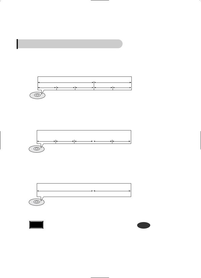
Disc terminology
Titles and chapters (DVD-VIDEO)
ïDVD-video is divided into several large sections called "titles" and smaller sections called "chapters". Numbers are allotted to these sections.
These numbers are called "title numbers" and "chapter numbers".
TITLE 1 |
|
TITLE 2 |
CHAPTER 1 CHAPTER 2 |
CHAPTER 3 |
CHAPTER 1 CHAPTER 2 |
Tracks (Video and music CDs)
ïVideo and music CDs are divided into sections called "tracks".
Numbers are allotted to these sections. These numbers are called "track numbers".
TRACK 1 |
TRACK 2 |
TRACK 3 |
TRACK 4 |
TRACK 5 |
Files (DivX)
ïDivX is divided into sections called "files".
Numbers are allotted to these sections. These numbers are called "file numbers".
FILE 1 |
FILE 2 |
Note |
• In this manual, the instructions marked with "DVD ( |
DVD |
)" are applicable |
to DVD-VIDEO and DVD-R/RW discs.
Where a particular DVD type is mentioned, it is indicated separately.
ï Depending on the content of the disc, the initial screen may appear
21
 Disc Playback
GB
1
3
Press OPEN/CLOSE button to open the disc tray.
Close the compartment by pressing the OPEN/CLOSE button again.
OPERATION
Note |
ï Depending on the content of |
button |
the disc, the initial screen may |
appear different.
ï Each country has a different video format standard.
ï For normal playback, the video format of the disc must be the same as the video |
|
format of your TV. |
22 |
|
|
 MP3/WMA-CD Playback
Data CDs (CD-ROM, CD-R, CD-RW) encoded in MP3/WMA format can be played.
Press the |
use |
OPEN/CLOSE button |
select |
to open the disc tray, |
then |
1 and then load the MP3/WMA disc.
and playback will start.
ï The appearance of the menu depends on the MP3/WMA disc.
ï WMA-DRM files cannot be played.
To change the album, use 


 to
to
3 select another album in Stop mode, and then press the ENTER button.
Press the STOP 4 button to stop
playback.
Note |
ï Depending on the recording mode, some MP3/WMA-CDs may not play. |
|
ï Table of contents of a MP3-CD varies depending on the MP3/WMA track |
|
format recorded on the disc. |

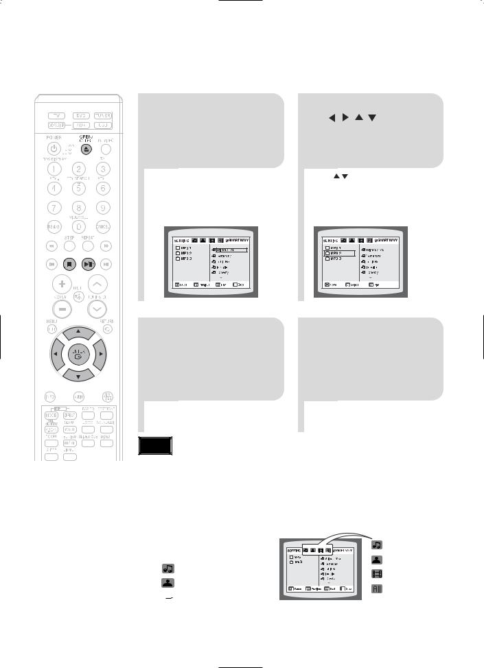
 To play a file icon in the screen,
Press the 


 button when it is in stop status and select a desired icon from the top part of the menu.
ï |
To play music files only, select the |
Icon. |
ï |
To view image files only, select the |
Icon. |
ïTo view movie files only, select the  Icon.
Icon.
ïTo select all files select the  Icon.
Icon.
ï
ï
ï
ï
Music File Icon
Image File Icon
Movie File Icon
All File Icon
23
Loading...