


HS50A
Table of contents
 Loading...
HS50A/HS60A
Service Manual

(Empty page)

Version 1.00
HS50A/HS60A
Service Manual
English
SM-HS50A/HS60A-ENG-01

(Empty page)

Safety Classifications
Classification
– Type of protection against electric shock: Class I
– Degree of protection against electric shock (when the patient is in physical contact): Type
BF or type CF applied part
– Degree of protection against harmful ingress of water: Ordinary equipment
– Degree of safety of use in the presence of flammable anesthetic agent mixed with air,
oxygen, or nitrous oxide: Equipment not suitable for use in the presence of flammable
anesthetic mixture with air or with oxygen or nitrous oxide.
– Mode of operation: Continuous operation
Electromechanical safety standards met
– Medical Electrical Equipment, Part 1: General Requirements for Basic Safety and
Essential Performance [IEC 60601-1:2005/A1:2012]
– Medical Electrical Equipment, Part 1-2: General Requirements for Basic Safety and
Essential Performance - Collateral Standards: Electromagnetic Compatibility -
Requirements and Tests [IEC 60601-1-2:2007]
– Medical Electrical Equipment, Part 1-6: General Requirements for Basic Safety and
Essential Performance - Collateral Standards: Usability [IEC 60601-1-6:2010]
– Medical Electrical Equipment, Part 2-37: Particular Requirements for the Basic Safety
and Essential Performance of Ultrasonic Medical Diagnostic and Monitoring Equipment
[IEC 60601-2-37:2007]
– Medical Electrical Equipment, Part 1: General Requirements for Safety [IEC 60601-
1:1988, A1:1991, A2:1995]
– Medical Electrical Equipment, Part 1-1: General Requirements for Safety - Collateral
Standards: General Requirements for Medical Electrical Systems [IEC 60601-1-1:2000]
– Medical Electrical Equipment, Part 1-2: General Requirements for Safety - Collateral
Standards: Electromagnetic Compatibility - Requirements and Tests [IEC 60601-1-2:2001,
A1:2004]
– Medical Electrical Equipment, Part 1-4: General Requirements for Safety - Collateral
Standards: Programmable Electrical Medical Systems [IEC 60601-1-4:1996, A1:1999]
– Medical Electrical Equipment, Part 2-37: Particular Requirements for the Basic Safety
and Essential Performance of Ultrasonic Medical Diagnostic and Monitoring Equipment
[IEC 60601-2-37:2001, A1:2004, A2:2005]
– Medical Devices - Application of Risk Management [ISO 14971:2007]
– Medical Electrical Equipment, Part 1: General Requirements for Safety [UL 60601-1:2003]
– Medical Electrical Equipment - Part 1: General Requirements for Basic Safety and
Essential Performance[CAN/CSA C22.2 No. 60601-1:14]

– Medical electrical equipment - part 1: General Requirements for Basic Safety and
Essential Performance [ANSI/AAMI ES60601-1:2005/(R)2012, AND C1:2009 AND
A2:2010(R)2012]
– Biological Evaluation of Medical Devices – Part 1: Evaluation and Testing [ISO 10993-1:
2009]
– Standard Means for Reporting the Acoustic Output of Medical Diagnostic Ultrasonic
Equipment [IEC 61157:2007]
Declarations
CSA mark with the indicators “C” and “US” means that the
product is certified for both US and Canadian markets according
to the applicable US and Canadian standards.
This mark certifies that the product conforms to applicable EEC
standards, and that it has been certified by the European
certification agency.
This is the manufacturer’s declaration of product compliance
with the applicable EEC directive(s).
This is the GMP symbol for Korean Good Manufacturing
Practice quality system regulation.

Precautions for Use
Be sure to read this Service Manual thoroughly to familiarize yourself with the operation of the
product and the relevant safety information before attempting to use the product.
• Keep this service manual near the product and refer to it when using the product.
• Be sure to familiarize yourself with the safety information contained in 'Chapter 2. Safety' and
'Chapter 10. Maintenance and Storage' in particular.
• This service manual does not include diagnosis results or opinions. In addition, please
consult the reference for each study area before evaluating the measurement result of an
application.
• This product is an ultrasound diagnostic system and cannot be used with your personal
computer. If you use this product in such an environment, we cannot be held responsible for
any resulting problems.
• This product must be used by a person who possesses clinical pathology training and/or
certification. Use by unqualified persons is prohibited.
• The manufacturer is not liable for any problems with the system caused by careless
operation and/or improper control by the operator.
• Product orders are based on individually agreed-upon specifications and may not include all
functions specified in this service manual.
• Some functions or options, probes, and the like may not be used in certain countries.
• All reference materials on standards, regulations, and related revisions are valid at the time
of publication of this service manual.
• Screen images in this service manual are examples only (may differ from the actual screen
or system).
• The content of this service manual is subject to change without prior notice.
• Products that are not manufactured by Samsung Medison are indicated with the trademarks
of their respective owners.
• The following terms are used to highlight the safety precautions that the user must be aware
of:
DANGER
Disregarding this instruction may result in death, serious
injury, or other dangerous
situations.
WARNING
Follow these instructions to prevent serious accidents or damage to property.
CAUTION
Follow these instructions to prevent minor accidents or damage to property.
NOTE
A piece of information
useful for installing, operating, and maintaining a system; not
related to any hazard.

Revision History
The revision history of this service manual is as follows:
Versi o n D AT E REASON FOR CHANGE
1.00.00 2016.07.15 Initial Release
If You Need Assistance
If you need a service manual or any assistance with the product, please contact the Samsung
Medison customer service department or your local vendor.

Patient Privacy Policy
Treatment of Patients' Personal Information
One of Samsung's social responsibilities is to recognize the importance of patient privacy and
handle and protect the personal information provided by patients in an appropriate manner.
Patient information stored in repaired and demo products should be handled as follows:
• Patient Information: IDs, names, DOBs, and images are information used to identify patients.
• Patient Information Management: Personal information provided by patients must be
protected during repairs and demonstrations. Do not use, distribute, or lose patient
information to third parties.
Management of Patient Information on Demo and Trade
Products
• Patient information stored on a product during the course of its use must be handled as the
patient desires. (delete or backup)
• When any demo or trade product is collected, patient information must be deleted if
requested by the patient to prevent its unintended distribution.
Management of Patient Information on Repaired Hospital
Products
• Before removing the product from hospital premises for repairs, all patient information should
be backed up to an external HDD or a memory device.
• Before removing the product from hospital premises, each patient should sign the patient
privacy agreement.

Request for Repairs and Patient Privacy Agreement
Date: MM/DD/YY
【Customer Information】
【Product Information】
Product name
Software version
S/N
Symptom
Stored item
□ None □ Main unit □ HDD □ DVD/CD
□ USB □ Photo □ Other ( )
Outsourced product
□ None
□ Provide details if applicable ( )
【Administration】
Handling date MM/DD/YY
Customer service
representative
※ Please sign inside the box below if you agree to the following:
□ Data saved on memory devices -- for example, hard disks -- may be lost during tests and
repairs.
□ Data saved on a product being repaired must be backed up by the customer.
□ Samsung will not be held responsible for any loss of data that are not backed up.
□ Samsung neither uses nor modifies patient information nor provides it to third parties.
【Customer Signature】
I entrust my product to ( ) for repair and agree to the policies above.
Date: MM/DD/YY Name: (Signature)
Hospital
Handler

Table of Contents 1
Table of Contents
Chapter 1. Introduction 1
1.1. Product Specifications ........................................................................................................ 2
1.2. Product Configuration ........................................................................................................ 5
1.2.1. Monitor .....................................................................................................................7
1.2.2. Control Panel ...........................................................................................................9
1.2.3. Console ................................................................................................................. 16
1.2.4. Peripheral Devices ................................................................................................ 19
1.2.5. Probes ................................................................................................................... 21
1.2.6. Accessories ........................................................................................................... 23
1.2.7. Optional Functions ................................................................................................ 24
Chapter 2. Safety 1
2.1. Purpose of Use .................................................................................................................... 2
2.1.1. Restrictions ..............................................................................................................2
2.2. Safety Information ............................................................................................................... 3
2.2.1. Safety Symbols ........................................................................................................3
2.2.2. LABEL ......................................................................................................................6
2.3. Electrical Safety ................................................................................................................... 7
2.3.1. Prevention of Electric Shock ....................................................................................7
2.3.2. Related Information ..................................................................................................9
2.3.3. ESD ..........................................................................................................................9
2.3.4. EMI ........................................................................................................................ 10
2.3.5. EMC ...................................................................................................................... 10
2.4. Mechanical Safety ............................................................................................................. 17
2.4.1. Moving the Equipment .......................................................................................... 17
2.4.2. Safety Notes .......................................................................................................... 18
2.5. Biological Safety ................................................................................................................ 20
2.5.1. ALARA Principle .................................................................................................... 20
2.6. Protecting the Environment ............................................................................................. 34
Chapter 3. Installing Product 1
3.1. Transporting......................................................................................................................... 2
3.1.1. Caution on Transporting...........................................................................................2

2 HS50/HS60 Service Manual
3.1.2. Brake ....................................................................................................................... 2
3.1.3. Precautions on Ramps ............................................................................................ 2
3.1.4. Humidity and Temperature ...................................................................................... 3
3.2. Unpacking the Product ....................................................................................................... 4
3.2.1. Dismantling the Product Box ................................................................................... 4
3.2.2. Accessories ............................................................................................................. 5
3.2.3. Release of the Locking Mechanism ......................................................................... 5
3.3. Installation Environment .................................................................................................... 6
3.3.1. Caution .................................................................................................................... 6
3.4. Installing the Product ......................................................................................................... 7
3.4.1. Installation Safety .................................................................................................... 7
3.4.2. Connecting Peripherals ........................................................................................... 9
3.5. System Power .................................................................................................................... 12
3.5.1. Turning the Power On............................................................................................ 12
3.5.2. Shutting down the System ..................................................................................... 12
3.6. System Settings ................................................................................................................ 13
3.6.1. ECG Setup ............................................................................................................. 14
3.6.2. General System Settings ....................................................................................... 16
3.6.3. Customize .............................................................................................................. 24
3.6.4. Peripherals ............................................................................................................. 26
3.6.5. Connectivity ........................................................................................................... 28
3.6.6. Service ................................................................................................................... 41
3.6.7. Help........................................................................................................................ 41
Chapter 4. Product Inspection 1
4.1. Inspecting the Functions .................................................................................................... 2
4.1.1. Basic Inspections ..................................................................................................... 2
4.1.2. Detailed Inspections ................................................................................................ 3
Chapter 5. Product Structure 1
5.1. Overview .............................................................................................................................. 3
5.2. System Block Diagram ....................................................................................................... 5
5.2.1. System Block Diagram ............................................................................................ 5
5.2.2. System Rack Design ............................................................................................... 6
5.3. Basic Structure of the Product .......................................................................................... 7
5.3.1. Electronic Structure ................................................................................................. 7
5.3.2. Ultrasound System Part ........................................................................................... 7
5.3.3. PC Part .................................................................................................................... 8
5.3.4. User Interface Part ................................................................................................... 8

Table of Contents 3
5.3.5. Power Part ...............................................................................................................8
5.4. Ultrasound System Part ...................................................................................................... 9
5.4.1. Main Functions of the PSA (Probe Select Assembly) ..............................................9
5.4.2. Beam Former Board .............................................................................................. 11
5.4.3. Back End Board .................................................................................................... 15
5.5. PC Part ................................................................................................................................ 19
5.5.1. PC Module ............................................................................................................ 19
5.5.2. Rear IO Board ....................................................................................................... 20
5.5.3. Software DSC ....................................................................................................... 21
5.6. User Interface Part ............................................................................................................. 23
5.6.1. Control Panel ........................................................................................................ 23
5.6.2. Main Monitor ......................................................................................................... 25
5.6.3. Touch-Screen ........................................................................................................ 26
5.6.4. Display Layout ....................................................................................................... 27
5.7. Power Part .......................................................................................................................... 28
5.7.1. ADM ...................................................................................................................... 28
5.7.2. Power Block Diagram ............................................................................................ 29
5.8. Interconnect Diagram ........................................................................................................ 30
5.8.1. HS50/HS60 Interconnect Diagram 1/2 .................................................................. 30
5.8.2. HS50/HS60 Interconnect Diagram 2/2 .................................................................. 31
5.8.3. Cable Description .................................................................................................. 32
Chapter 6. Service Mode 1
6.1. Service Mode........................................................................................................................ 3
6.1.1. How to Shift to Service Mode ...................................................................................3
6.2. Service Information ............................................................................................................. 4
6.3. Configuration ....................................................................................................................... 5
6.3.1. Clock ........................................................................................................................5
6.3.2. Keyboard/Region .....................................................................................................5
6.3.3. TCP/IP ......................................................................................................................6
6.3.4. Option .......................................................................................................................7
6.3.5. User Account and User Account Management ........................................................8
6.3.6. Printer .......................................................................................................................9
6.4. System ................................................................................................................................ 10
6.4.1. Upgrade Software ................................................................................................. 10
6.4.2. System Serial Number .......................................................................................... 11
6.4.3. Window Explorer ................................................................................................... 12
6.4.4. Install Recovery System........................................................................................ 13
6.5. Diagnostics ........................................................................................................................ 14

4 HS50/HS60 Service Manual
6.5.1. Control Panel Test ................................................................................................. 14
6.5.2. Keyboard Test ....................................................................................................... 14
6.5.3. Power On Self Test................................................................................................ 14
6.5.4. Built in Self Test ..................................................................................................... 14
6.5.5. Monitor Test ........................................................................................................... 14
6.6. Backup and Restore ......................................................................................................... 15
6.6.1. Backup ................................................................................................................... 15
6.6.2. Restore .................................................................................................................. 15
6.6.3. Log Backup ............................................................................................................ 15
6.7. Report ................................................................................................................................. 16
6.7.1. Report .................................................................................................................... 16
6.8. Demo Play .......................................................................................................................... 17
6.8.1. Demo Play ............................................................................................................. 17
6.9. Entering the Installation Key............................................................................................ 18
Chapter 7. Troubleshooting 1
7.1. Power Issues ....................................................................................................................... 2
7.1.1. Power Does Not Turn on ......................................................................................... 2
7.1.2. Power Does Not Turn off ......................................................................................... 2
7.1.3. Power Turns off by Itself .......................................................................................... 2
7.2. Monitor ................................................................................................................................. 3
7.2.1. Nothing Is Displayed on the Screen ........................................................................ 3
7.2.2. Screen is Discolored ................................................................................................ 3
7.3. Error Messages ................................................................................................................... 4
7.3.1. Error Occurs During Booting ................................................................................... 4
7.4. Image .................................................................................................................................... 4
7.4.1. 2D Mode: There is No IMAGE ECHO or IMAGE FORMAT .................................... 4
7.4.2. Lines (Noise) Appear in 2D Mode Image ................................................................ 4
7.4.3. M, C, PW, CW Mode Trouble .................................................................................. 4
7.5. USD Device Detection Failure ............................................................................................ 5
7.5.1. Failed to recognize the USB (Removable device) device ....................................... 5
7.6. Trouble Shooting Tree ........................................................................................................ 6
Chapter 8. Disassembly and Assembly 1
8.1. Power Issues ....................................................................................................................... 2
8.1.1. Preparation .............................................................................................................. 2
8.2. Disassembling the Product ................................................................................................ 3
8.2.1. Rear Side Disassembly ........................................................................................... 3

Table of Contents 5
8.2.2. HDD Disassembly ....................................................................................................5
8.2.3. Front End Disassembly ............................................................................................6
8.2.4. Control Panel Disassembly ......................................................................................7
8.2.5. Touch Panel Disassembly........................................................................................8
8.2.6. Dust Filter and Fan Disassembly .............................................................................9
8.2.7. ODD Disassembly ................................................................................................. 10
8.2.8. Monitor Disassembly ............................................................................................. 11
Chapter 9. Probes 1
9.1. Probes ................................................................................................................................... 2
9.1.1. Probe List .................................................................................................................2
9.1.2. Ultrasound Transmission Gel ................................................................................ 18
9.1.3. Sheaths ................................................................................................................. 19
9.1.4. Probe Safety Precautions ..................................................................................... 19
9.1.5. Cleaning and Disinfecting the Probe ..................................................................... 21
9.2. Biopsy ................................................................................................................................. 37
9.2.1. Biopsy Kit Components ......................................................................................... 37
9.2.2. Using the Biopsy Kit .............................................................................................. 38
9.2.3. Assembling the Biopsy Kit..................................................................................... 40
9.2.4. Cleaning and Disinfecting the Biopsy Kit .............................................................. 43
Chapter 10. Maintenance 1
10.1. Operational Environment .................................................................................................... 2
10.2. Product Maintenance .......................................................................................................... 3
10.2.1. Cleaning and Disinfecting ........................................................................................3
10.2.2. Cleaning Air Filters ...................................................................................................6
10.2.3. Accuracy Checks .....................................................................................................7
10.3. Data Maintenance ................................................................................................................ 8
10.3.1. User Settings Backup ...............................................................................................8
10.3.2. Backing Up Patient Information ...............................................................................8
10.3.3. Software ...................................................................................................................8
Chapter 11. Service Parts List 1
11.1. Body Cover Parts ................................................................................................................ 2
11.2. Control Panel Parts ............................................................................................................. 9
11.3. Monitor & Arm Parts .......................................................................................................... 17
11.4. System Parts ...................................................................................................................... 21
11.5. System Cable Parts ........................................................................................................... 24

Chapter 1
1. Introduction
Chapter 1. Introduction
Introduction
1.1. Product Specifications ....................................................................................................... 2
1.2. Product Configuration ........................................................................................................ 5
1.2.1. Monitor .................................................................................................................... 7
1.2.2. Control Panel .......................................................................................................... 9
1.2.3. Console................................................................................................................. 16
1.2.4. Peripheral Devices ............................................................................................... 19
1.2.5. Probes .................................................................................................................. 21
1.2.6. Accessories .......................................................................................................... 23
1.2.7. Optional Functions ................................................................................................ 24

1 - 2 HS50/HS60 Service Manual
1.1. Product Specifications
Physical
Dimensions
Height: 1344 mm (with Monitor)
Width: 529 mm
Depth: 767 mm (with Keyboard)
Weight: 79.8kg (without accessories)
Weight: Approx. 98kg (with Safe Working Load)
Imaging Modes
2D Mode
M Mode
Color M Mode
Anatomical Mode
Color Doppler Mode
Pulsed Wave (PW) Spectral Doppler Mode
Continuous Wave (CW) Doppler Mode
Tissue Doppler Imaging (TDI) Mode
Tissue Doppler Wave (TDW) Mode
Power Doppler (PD) Mode
ElastoScan Mode
3D/4D/XI STIC imaging Mode
Dual Mode
Quad Mode
Combined Mode
Simultaneous Mode
Zoom Mode
Gray Scale
256 (8 bits)
Focusing
Transmit focusing, maximum of eight points (four points simultaneously
selectable)
Digital dynamic receive focusing (continuous)
Probes
(Type BF/IPX7)
Linear Array
LA3-14AD, LA2-9A, LA3-16AI, LA4-18BD, LA3-16A
Curved Array
CA1-7AD, CA2-9AD, CA2-6BM, CF4-9
Endo Cavity
ER4-9, EA2-11B
Phased Array
PA1-5A, PA3-8B, PE2-4
3D
CV1-8AD, V5-9
CW
CW6.0, DP2B
Chapter 1. Introduction 1 - 3
NOTE
•
HS50 does not support LA2-9A and LA3-16AI, EA2-11B,
LA4-18BD, PA1-5A.
•
HS60 does not support PE2-4 and ER4-9.
Probe
Connections
3 Probe Connectors, 4 Probe Connectors for option
NOTE
HS50 HS60
3 PORT O X
4 PORT O (Option) O
CW Probe Connector
Monitor
Main Monitor
Number of Pixel: 1920 x 1080
21.5 inch LCD Monitor (LED Backlight unit, hereafter referred to as “LCD
monitor”)
Touch Screen Monitor
Number of Pixel: 1280 x 800
10.1 inch LCD Monitor (LED Backlight unit, hereafter referred to as “LCD
monitor”)
ECG
USB Type (Type CF)
Rear Panel
Input/Output
Connections
Audio Output Port (Right/Left)
VGA monitor
LAN
USB Port
HDMI output
Image Storage
Maximum 45,000 frames for Cine memory
Maximum 14,000 Lines for Loop memory
Image filing system
Application
Obstetrics, Gynecology, Urology, Abdomen, Cardiac, Vascular, Small
Parts, TCD, MSK, Pediatric
Electrical
Parameters
100-240VAC, 800VA, 50/60Hz
Measurement
Packages
Abdomen, Obstetrics, Gynecology, MSK, Pediatric, Small Parts, Urology,
Vascular, Cardiac, Fetal Heart
* For additional information, refer to the ‘Chapter 8. Measurements and
Calculations’ in the user manual.

1 - 4 HS50/HS60 Service Manual
Signal
Processing
(Pre-
processing)
Acoustic Power Control
Dynamic Aperture Control
Dynamic Apodization Control
Dynamic LPF Control
Signal
Processing
(Post-
processing)
Digital TGC Control
Slider TGC Control
Mode-Independent Gain Control
Black Hole/Noise Spike Filtering
1D Lateral/Axial Filtering
2D Edge/Blurring Filtering
Frame average
M/D Mode Sweep Speed Control
Zoom
Image View Area Control
Image Orientation (left/right and up/down)
Measurement
Trackball operation of multiple cursors
2D mode: Linear measurements and area measurements using elliptical
approximation or trace
M mode: Continuous readout of distance, time, and slope rate
Doppler mode: Velocity and trace
Auxiliary
DVD Multi-Drive
Digital B/W Video Printer
Digital Color Video Printer
USB Printer
DVD Recorder
Foot switch (IPX8)
USB Flash Memory Media
USB HDD
USB ECG
Monitor
User Interface
English, German, French, Spanish, Italian, Portuguese
Pressure Limits
Operating: 700 – 1060hPa
Storage: 700 – 1060hPa
Humidity Limits
Operating: 30 – 75%
Storage & Shipping: 20 – 90%
Temperature
Limits
Operating: 10 – 35°C
Storage & Shipping: -25 – 60°C
Chapter 1. Introduction 1 - 5
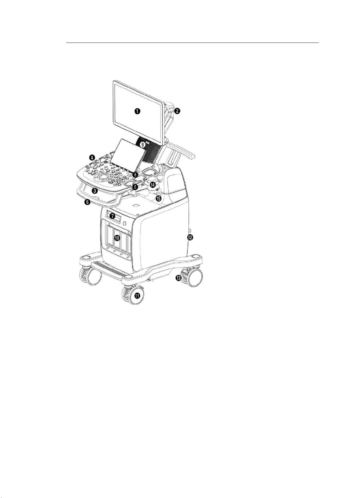
1.2. Product Configuration
This product consists of monitor, control panel, console, peripheral devices and probes.
① Monitor
② Monitor arm
③ Keyboard
④ Control panel
⑤ Lift
⑥ Probe holder
⑦ DVD drive
⑧ USB port
⑨ Speaker
⑩ Probe port
⑪ Wheel
⑫ Location of ID Label
⑬ Brake
⑭ Gel warmer
⑮ Internal peripheral devices
outlet
[Figure 1.1 Front of the Product]
1 - 6 HS50/HS60 Service Manual
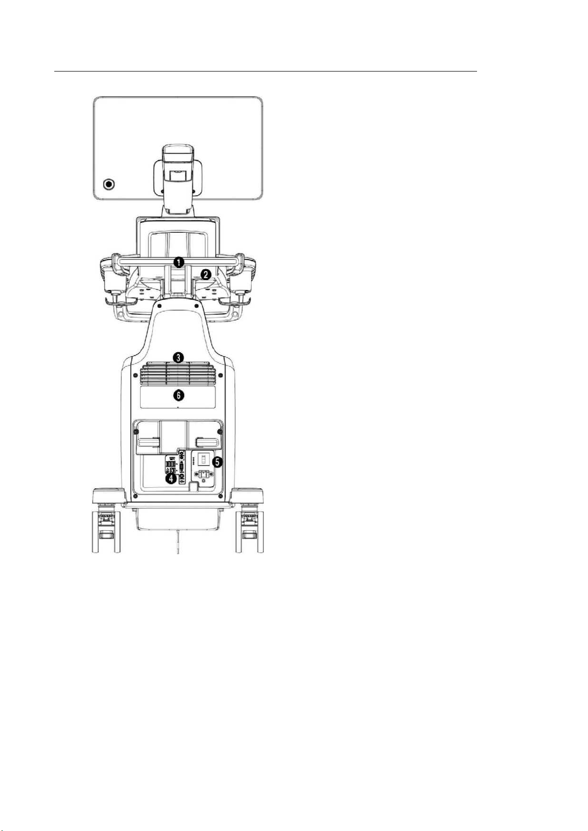
[Figure 1.2 Back of the Product]
① Handle
② Storage compartments
③ Ventilation
④ Rear panel
⑤ Power connection part
⑥ ID label
Chapter 1. Introduction 1 - 7
1.2.1. Monitor
Ultrasound images and other information are displayed on the color LCD monitor.
1.2.1.1. Screen Layout
The monitor displays ultrasound images, operation menus and a variety of other information.
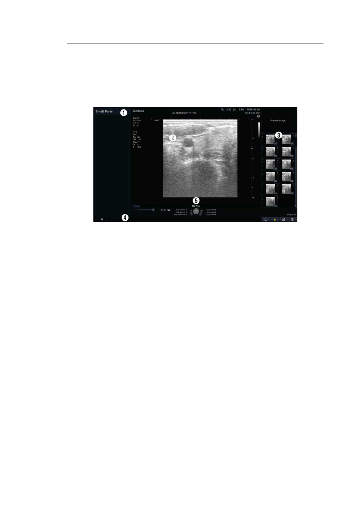
[Figure 1.3 Monitor Display]
① Title Area
Displays patient information, hospital name, application, frame rate, depth, probe
information, acoustic output information, and the current date and time.
② Image Area
Displays ultrasound images. Image information, annotation, and measurement
information are also displayed.
③ Thumbnail Area
Images saved by pressing the preset Store button are shown in the thumbnails. When
you save Single screens, up to 4 images are shown in a list; for Quad screens, up to 12
images are shown. Click it with the pointer to enlarge the preview image.
④ User Information and Status Information Area
Information that is useful to the user, such as current system status, image information,
selectable items, etc., is displayed.
⑤ User Key (User Defined Key) Area
Settings for User Defined Keys, including the positions of Set and Exit buttons, are
displayed. You can change the setting of each button in Setup > Customize > Buttons.

1 - 8 HS50/HS60 Service Manual
NOTE
For information on User Key Setup, please refer to
‘Chapter 3. Utilities’ in the user
manual.
TIP
Principles of Operation of the Diagnostic Ultrasound System
Medical ultrasound images are created by digital memory and computer when they convert
the high-frequency wave signals that are transmitted and received by the probe.
As ultrasound waves propagate through the human body, they generate reflected signals
whenever they encounter a change in density. For example, reflected signals are generated
when signals pass from fatty tissues to muscle tissues. Reflected signals return to the probe,
where they are converted into electronic signals. The reflected signals are amplified and
processed by analog and digital circuits that have filters for various frequencies and response
time options. Then they are again converted into high-frequency electronic signals, and
saved as a series of digital image signals. The monitor displays the image signals stored on
the storage device in real time. The entire process of transmitting, receiving, and processing
signals is controlled by the computer.
Chapter 1. Introduction 1 - 9
1.2.2. Control Panel
The system can be controlled by using the control panel.
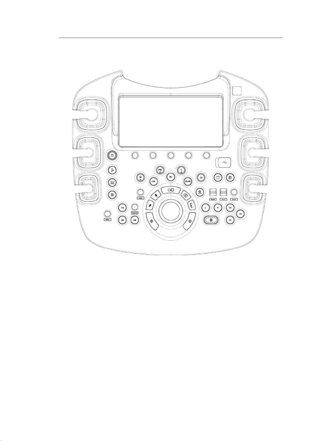
[Figure 1.4 Control Panel]
The control panel consists of a keyboard, soft menus, buttons, dials, dial-buttons, a slider, and a
trackball.
The dial-button can be used both as a dial and a button.
1 - 10 HS50/HS60 Service Manual
1.2.2.1. Functions of the Control Panel
The following are the descriptions and instructions for the controls on the control panel. For
more information on controls with multiple functions, see ‘Chapter 3. Utilities’ and later in the
user manual.
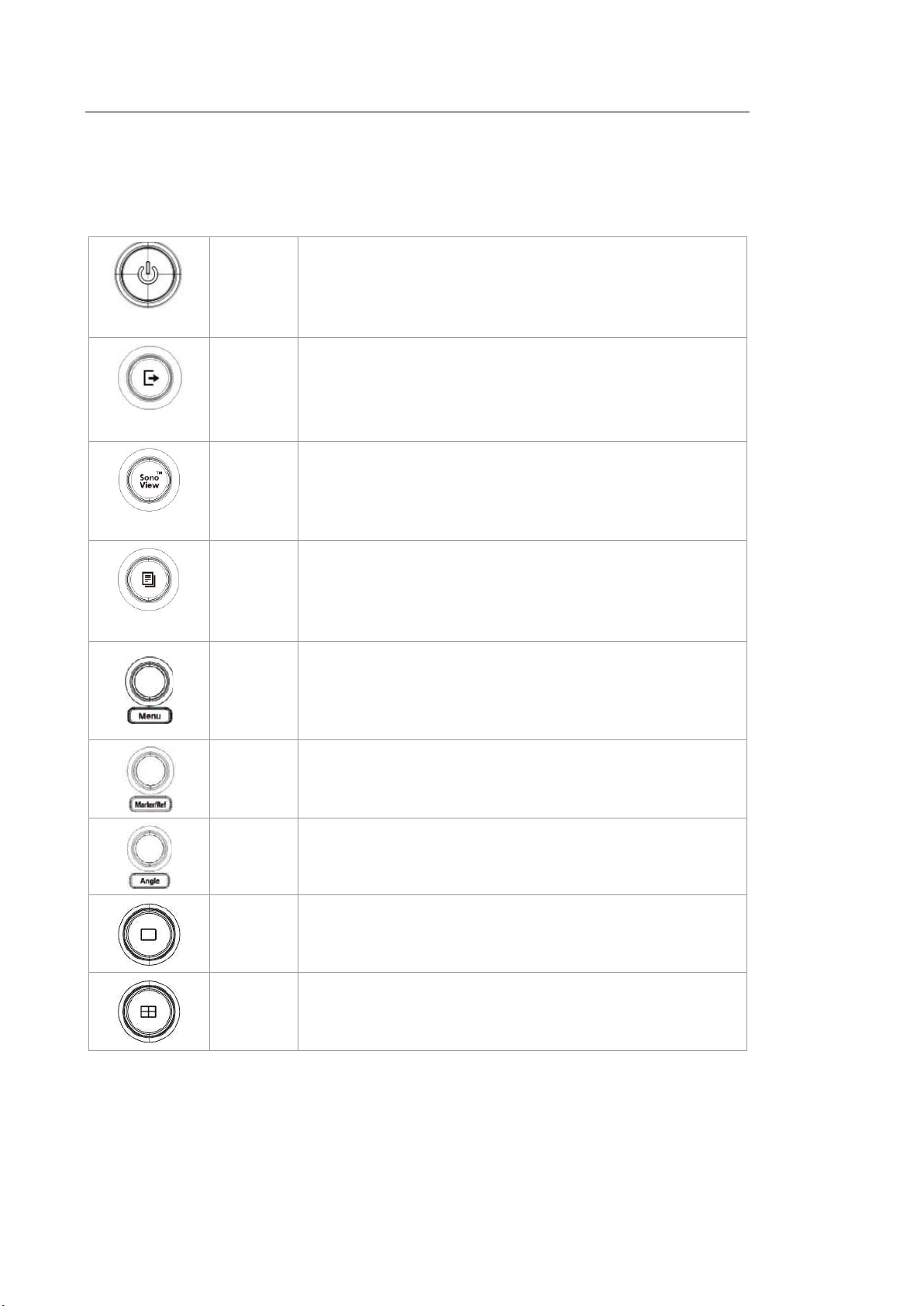
On/Off
Button Turns the system on/off.
End Exam
Button
Finishes the exam of the currently selected patient and resets
the related data.
SonoView
Button Displays the screen for viewing and managing stored images.
Report
Button
Displays the Report screen that shows the measurement
results of the current application and other information.
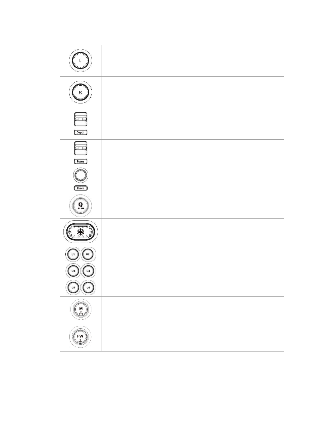
Dial-
button
When you press the dial-button, the menu items that are
available in the current scan mode are shown on screen.
Rotating the Menu dial-button to the right selects the menu one
row above the current menu selected, and rotating it to the left
selects the menu one row below.
Dial-
button
– Marker: Allows the user to enter a BodyMarker over an
image.
– Ref: Moves the reference slice horizontally in 3D View.
Dial-
button
Adjusts the angle of the sample volume in Spectral Doppler
mode. It is also used to adjust the Arrow’s angle or the probe
angle for a BodyMarker.
Button In this mode, only the image is displayed on the screen.
Button Compares four independent images.
Chapter 1. Introduction 1 - 11
Button
Compares two independent images. The active image mode is
on the left.
Button
Compares two independent images. The active image mode is
on the right.
Switch Adjusts the scanning depth of the image.
Switch Moves the focus to the target area for observation.
Dial-
button
Makes the Zoom Box appear.
In order to close the Zoom mode, press the Exit button.
Button
Press this button to turn the Quick Scan function on. The ‘Q
scan’ mark will appear at the top of an image. It can be used in
applications of all probes.
Button Pauses/resumes scanning.
Button
Stands for User Key; functions can be assigned to these
buttons as desired. The function for each button can be
assigned in Setup > Customize > Buttons > User Key.
Dial-
button
Start or end M Mode. Rotate this dial-button to adjust Gain.
Also, turning this dial-button when in 3D View rotates the
image along the x-axis.
Dial-
button
Press this button to start/stop PW Spectral Doppler mode.
Rotate this dial-button to adjust Gain.
Also, turning this dial-button, when in 3D View rotates the
image along the y-axis.
1 - 12 HS50/HS60 Service Manual
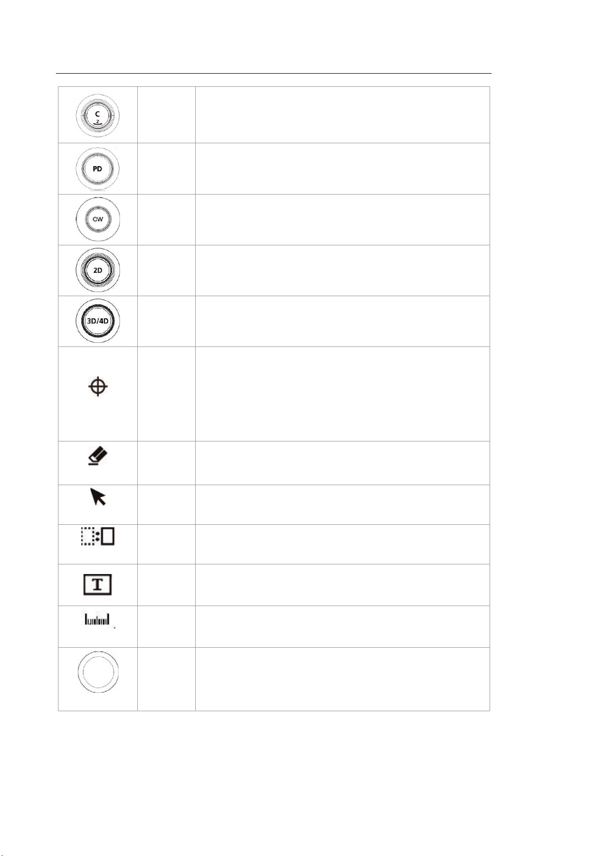
Dial-
button
Press this button to start/stop Color Doppler mode. Rotate this
dial-button to adjust Gain.
Also, turning this dial-button when in 3D View rotates the
image along the z-axis.
Button Press this button to start/stop Power Doppler mode.
Button
Press this button to start/stop CW Spectral Doppler mode.
Available only with the phased array probe.
Dial-
button
Press this button to start 2D mode. Rotate this dial-button to
adjust Gain.
Button Press this button to turn 3D/4D Mode on/off.
Set/Exit
Button
Set or Exit function may be assigned to this button. The
function for each button can be assigned in Setup > Customize
> Set/Exit Key.
– Set: Select an item or value using the trackball. Also used
to change the function of the trackball.
– Exit: Exits the function currently being used and returns to
the previous state.
Clear
Button
Deletes text, Arrow, BodyMarker, measurement results, etc.
displayed on an image.
Pointer
Button
When this is pressed, an arrow marker appears to point to
parts of the displayed image.
Change
Button Changes the current trackball function.
Button Allows the user to place text on an image.
Calculator
Button Starts measurements by application.
Trackball
Trackball
Moves the cursor on the screen. Also scrolls through Cine
images.
Chapter 1. Introduction 1 - 13
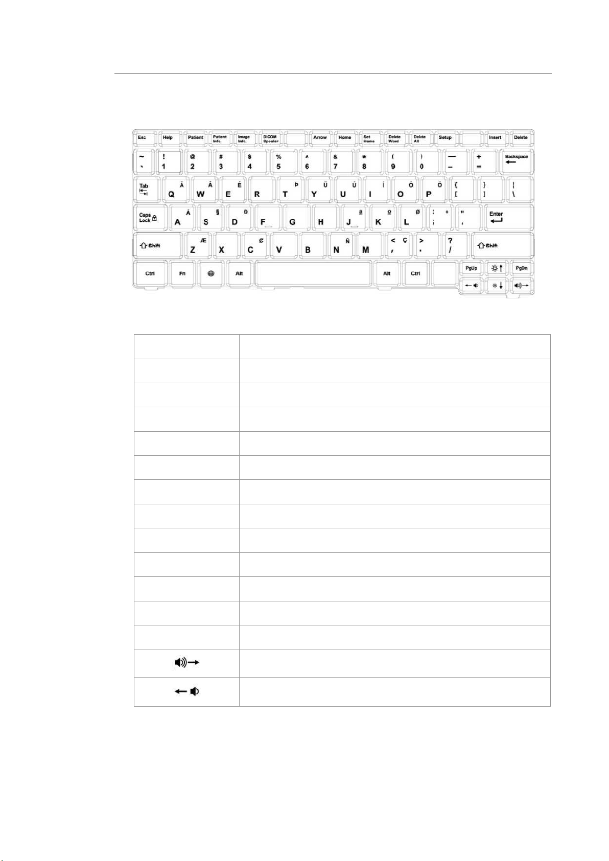
■ Keyboard
The keyboard is used to type in text.
[Figure 1.5 Keyboard]
Help Displays the Help Manual on the screen.
Patient Displays the General Information on the screen.
Patient info. Shows or hides the patient information on the screen.
Image Info. Shows or hides the Image Parameters on the screen.
DICOM Spooler Displays the DICOM Spooler on the screen.
Arrow Initiates Arrow mode.
Home Moves the cursor to the Home position in Annotation mode.
Set Home Specifies the Home position in Annotation mode.
Delete Word Deletes the last text entered in Annotation mode.
Delete All Deletes all the text that has been entered in Annotation mode.
Setup This displays the Setup screen.
Insert Select an input method.
Delete Deletes text.
Turns up the speaker volume.
Turns down the speaker volume.
1 - 14 HS50/HS60 Service Manual
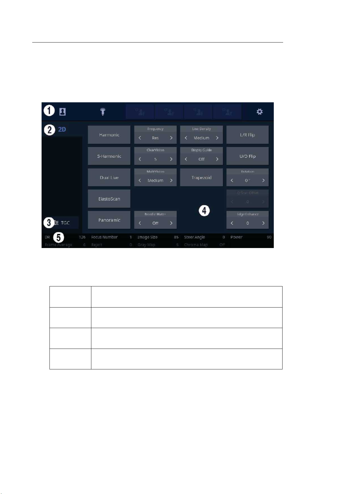
1.2.2.2. Touch Screen
The touch screen is an operating tool that can be touched by the user to input data. The
functions that are available in the current mode are shown in the form of buttons or a dial-
button.
■ Touch Screen Layout
[Figure 1.6 Touch Screen Display]
① These buttons are always displayed on the touch screen. Buttons that are in use are
shown in blue and buttons that cannot be used are deactivated.
Patient
The Patient Information screen will appear, where you can select a
Patient ID in the list or enter new patient information.
Probe
It displays the Probe Selection screen where you can select and
modify the probe and application.
Quick
Preset 1–4
It shows up to 4 Preset buttons configured at Setup.
Setup
The general system settings that do not have a direct bearing on
imaging are explained below.
Loading...