


 Loading...
INSTALLATION MANUAL
CODE: 00ZMF9841/I1E
DIGITAL FULL COLOR
MULTIFUNCTIONAL SYSTEM
MF 9626
MF 9631
MODEL MF 9841
CONTENTS
CONFIGURATION
[1] MF 9626/9631/9841 (Main Unit) . . . . . . . . . . . . . . . . . . . . . . . . . . . . . . . . . . . . . . . . . . . 1-1 [2] SG-CPX4/CPX6 (Stand/2x500 sheet paper drawer) . . . . . . . . . . . . . . . . . . . . . . . . . . . 2-1 [3] SG-ETX1/ETX2 (Exit tray unit) . . . . . . . . . . . . . . . . . . . . . . . . . . . . . . . . . . . . . . . . . . . . 3-1 [4] SG-GCX1 (Large capacity tray) . . . . . . . . . . . . . . . . . . . . . . . . . . . . . . . . . . . . . . . . . . . 4-1 [5] SG-FNX3 (Inner Finisher). . . . . . . . . . . . . . . . . . . . . . . . . . . . . . . . . . . . . . . . . . . . . . . . 5-1 [6] SG-PMX1 (Punch module) . . . . . . . . . . . . . . . . . . . . . . . . . . . . . . . . . . . . . . . . . . . . . . . 6-1 [7] SG-BPX2 (Paper pass unit) . . . . . . . . . . . . . . . . . . . . . . . . . . . . . . . . . . . . . . . . . . . . . . 7-1 [8] SG-FNX4 (Saddle stitch finisher) . . . . . . . . . . . . . . . . . . . . . . . . . . . . . . . . . . . . . . . . . . 8-1 [9] SG-PMX2 (Punch module) . . . . . . . . . . . . . . . . . . . . . . . . . . . . . . . . . . . . . . . . . . . . . . . 9-1 [10] SG-FEX2 (Facsimile expansion kit) . . . . . . . . . . . . . . . . . . . . . . . . . . . . . . . . . . . . . . 10-1 [11] SG-IFX1 (Internet fax expansion kit). . . . . . . . . . . . . . . . . . . . . . . . . . . . . . . . . . . . . . .11-1 [12] SG-KBX1 (Keyboard) . . . . . . . . . . . . . . . . . . . . . . . . . . . . . . . . . . . . . . . . . . . . . . . . . 12-1 [13] SG-ECK1 (Enhanced compression kit). . . . . . . . . . . . . . . . . . . . . . . . . . . . . . . . . . . . 13-1 [14] SG-DSK2/DSK3 (Data security kit). . . . . . . . . . . . . . . . . . . . . . . . . . . . . . . . . . . . . . . 14-1 [15] SG-PSX1 (PS3 expansion kit) . . . . . . . . . . . . . . . . . . . . . . . . . . . . . . . . . . . . . . . . . . 15-1 [16] SG-XEK1 (XPS expansion kit) . . . . . . . . . . . . . . . . . . . . . . . . . . . . . . . . . . . . . . . . . . 16-1 [17] SG-MEK1 (Expansion memory board) . . . . . . . . . . . . . . . . . . . . . . . . . . . . . . . . . . . . 17-1 [18] SG-BF1 (Barcode font kit) . . . . . . . . . . . . . . . . . . . . . . . . . . . . . . . . . . . . . . . . . . . . . 18-1 [19] SG-AMX2 (Application communication module). . . . . . . . . . . . . . . . . . . . . . . . . . . . . 19-1 [20] SG-AMX3 (External account module). . . . . . . . . . . . . . . . . . . . . . . . . . . . . . . . . . . . . 20-1
Parts marked with "  " are important for maintaining the safety of the set. Be sure to replace these parts with specified ones for maintaining the safety and performance of the set.
This document has been published to be used for after sales service only. The contents are subject to change without notice.

CONFIGURATION
1. Main unit and option
STAPLE CARTRIDGE |
|
11STP-FNX1 |
|
STAPLE CARTRIDGE |
|
12 STP-FNX4 |
PAPER PASS UNIT |
(For saddle) |
7 SG-BPX2 |
SADDLE STITCH
8 FINISHER
SG-FNX4
10 PUNCH MODULE
SG-PMX2
13 |
PS3 EXPANSION KIT |
15 |
BARCODE FONT KIT |
SG-PSX1 |
SG-BF1 |
XPS EXPANSION KIT
14 SG-XEK1
Image send expansion
|
FACSIMILE |
|
INTERNET FAX |
|
ENHANCED |
16 |
EXPANSION KIT |
17 |
EXPANSION KIT |
18 |
COMPRESSION KIT |
SG-FEX2 |
SG-IFX1 |
SG-ECK1 |
|
|
|
|
DESKTOP DOCUMENT |
|
|
|
|
|
||
19 |
DATA SECURITY KIT |
|
MANAGER |
|
|
|
|
|
|||
|
21 |
5 LICENSE KIT |
24 |
|
|
|
|||||
SG-DSK2 |
|
||||||||||
SG-LX5 |
|
|
|
||||||||
|
|
|
|
|
|
|
|
|
|||
|
|
DATA SECURITY KIT |
|
DESKTOP DOCUMENT |
|
|
|
|
|
||
|
|
|
|
MANAGER |
|
|
|
|
|
||
20 SG-DSK3 |
|
25 |
|
|
|
||||||
22 |
50 LICENSE KIT |
|
|
|
|||||||
|
|
|
|||||||||
|
|
|
SG-LX50 |
|
|
|
|
|
|||
|
|
|
|
DESKTOP DOCUMENT |
|
|
|
|
|
||
|
|
|
|
MANAGER |
|
|
|
|
|
||
|
|
|
23 |
100 LICENSE KIT |
|
|
|
|
|
||
|
|
|
|
|
|
|
|
|
|||
|
|
|
SG-LX100 |
|
|
|
|
|
|||
|
|
EXPANSION |
|
|
|
|
|
|
|
|
|
|
|
|
|
|
|
|
|
|
|
|
|
27 |
|
MEMORY BOARD |
|
26 |
KEYBOARD |
|
|||||
|
|
|
|
||||||||
|
SG-MEK1 |
|
|
||||||||
|
|
|
|
|
|
|
|||||
|
|
|
|
|
SG-KBX1 |
|
|||||
4
5
EXIT TRAY UNIT
SG-ETX1
EXIT TRAY UNIT
SG-ETX2
MF 9841 CONFIGURATION - i
2. Combination of options
Section |
|
Name |
Model name |
MF |
MF 9841 |
Product |
Remarks |
|
9626/9631 |
key target |
|||||
|
|
|
|
|
|
||
Paper feed |
1 |
STAND/2 x 500 SHEET PAPER DRAWER |
SG-CPX4 |
{ |
|
|
|
system |
2 |
STAND/2 x 500 SHEET PAPER DRAWER |
SG-CPX6 |
|
{ |
|
|
|
3 |
LARGE CAPACITY TRAY |
SG-GCX1 |
{ |
{ |
|
A4 |
Paper exit system |
4 |
EXIT TRAY UNIT |
SG-ETX1 |
{ |
|
|
|
|
5 |
EXIT TRAY UNIT |
SG-ETX2 |
|
{ |
|
|
|
6 |
FINISHER |
SG-FNX3 |
{ |
{ |
|
Inner finisher |
|
7 |
PAPER PASS UNIT |
SG-BPX2 |
{ |
{ |
|
|
|
8 |
SADDLE STITCH FINISHER |
SG-FNX4 |
{ |
{ |
|
|
|
9 |
PUNCH MODULE |
SG-PMX1 |
{ |
{ |
|
For inner finisher |
|
10 |
PUNCH MODULE |
SG-PMX2 |
{ |
{ |
|
For saddle stitch finisher |
|
11 |
STAPLE CARTRIDGE |
STP-FNX1 |
{ |
{ |
|
For finisher |
|
12 |
STAPLE CARTRIDGE |
STP-FNX4 |
{ |
{ |
|
For saddle |
Printer expansion |
13 |
PS3 EXPANSION KIT |
SG-PSX1 |
{ |
{ |
{ |
|
|
14 |
XPS EXPANSION KIT |
SG-XEK1 |
{ |
{ |
{ |
SG-MEX1 is required. |
|
15 |
BARCODE FONT KIT |
SG-BF1 |
{ |
{ |
|
|
Image send |
16 |
FACSIMILE EXPANSION KIT |
SG-FEX2 |
{ |
{ |
|
|
expansion |
17 |
INTERNET FAX EXPANSION KIT |
SG-IFX1 |
{ |
{ |
{ |
|
|
18 |
ENHANCED COMPRESSION KIT |
SG-ECK1 |
|
{ |
|
|
Authentication/ |
19 |
DATA SECURITY KIT |
SG-DSK2 |
{ |
|
{ |
Commercial version |
Security |
20 |
DATA SECURITY KIT |
SG-DSK3 |
|
{ |
{ |
|
Application/ |
21 |
DESKTOP DOCUMENT MANAGER |
SG-LX5 |
{ |
{ |
|
|
Solution |
|
5 LICENSE KIT |
|
|
|
|
|
|
22 |
DESKTOP DOCUMENT MANAGER |
SG-LX50 |
{ |
{ |
|
|
|
|
50 LICENSE KIT |
|
|
|
|
|
|
23 |
DESKTOP DOCUMENT MANAGER |
SG-LX100 |
{ |
{ |
|
|
|
|
100 LICENSE KIT |
|
|
|
|
|
|
24 |
APPLICATION COMMUNICATION |
SG-AMX2 |
{ |
{ |
{ |
|
|
|
MODULE |
|
|
|
|
|
|
25 |
EXTERNAL ACCOUNT MODULE |
SG-AMX3 |
{ |
{ |
{ |
|
|
26 |
KEYBOARD |
SG-KBX1 |
{ |
{ |
|
|
Memory |
27 |
EXPANSION MEMORY BOARD |
SG-MEK1 |
{ |
{ |
|
1GB |
MF 9841 CONFIGURATION - ii

[1] MF 9626/9631/9841
1.Installing (use) conditions
Before installing the machine, check that the following installing (use) conditions are satisfied.
If the installing (use) conditions are not satisfied, the machine may not display full performances, resulting in troubles. It may also cause safety problems. Therefore, be sure to arrange the installing (use) conditions before setting up the machine.
No |
Content |
1 |
Delivery notes |
2 |
Installation area |
3 |
Power source (Capacity, fluctuation, safety) |
4 |
Floor strength |
5 |
Environmental conditions |
A. Delivery notes
For installation of a large size machine, be sure to check that the door size is great enough before bringing in.
B. Installation area
The following space must be provided around the machine in order to assure machine performances and proper operations.
If any option is installed, provide the additional space for installing it.
Especially the space at the rear of the machine must be provided sufficiently. If not, the machine cannot exhibit functions against heat and dust, causing some troubles.
30cm
(4)Safety
Be sure to properly ground the machine.
(5)Power plug
Check the form of the power plug. If the shape does not match, do not use it.
D. Floor strength and level
This machine is considerably heavy and becomes heavier with an option installed. The floor must be strong enough for assuring safety.
If the floor is not level, the toner density control is not normal, and the copy quality may be adversely affected.
E. Environmental conditions
(1)Temperature and humidity
This machine is designed to perform properly under the specified temperature and humidity. If the temperature and humidity exceeds the specified range, the machine may not operate properly and or cause equipment failure.
Especially when the humidity is too high, paper absorbs humidity to cause a paper jam or dirty copy.
Do not install the machine near a heater, a cooler, or a humidifier.
30cm |
45cm |
C.Power source (Capacity, voltage, frequency, safety, plug)
If the power specifications are not satisfied, the machine cannot exhibit full performances and may cause safety trouble.
Strictly observe the following specifications.
(1)Power capacity
Check that the following power capacity is satisfied. If not, additionally provide a power source.
Current capacity |
|
Japan |
20A or more |
EX 100V |
15A or more |
EX 200V |
10A or more |
(2)Power voltage
Measure the voltage during copying to check that the voltage is in the range of the specified voltage ±10%.
If the voltage is outside the specified range, use thicker lead wires to reduce impedance.
(An electrical work is required.)
Use of a step-up transformer is also available. In this case, the capacity must be great enough for the max. power consumption of the machine.
(3)Power frequency, waveform
The frequency must be within the range of the specified frequency
±2%. If power waveform is deformed, a trouble may occur.
Dew may be formed inside the machine to cause a trouble. Use enough care for ventilation.
Humidity (RH) |
|
|
85% |
|
|
60% |
|
|
20% |
|
|
10 |
30 |
35 |
•Working environment Temperature: 10 to 35°C Humidity: 20 to 85% RH
Atmospheric pressure: 590 to 1013hPa (altitude: 0 to 2000 m)
MF 9841 MF 9626/9631/9841 1 – 1

(2)Dust
If dust enters the machine, it may cause dirty copy and a paper jam, resulting in a shortened lifetime.
(3)Direct rays of sunlight
If the machine is installed under the rays of the sun, the exterior of the machine may be discolored and abnormal copies may be produced.
(4)Gases and chemicals
Do not install the machine at a place where there are gases and chemicals. Especially be careful to avoid installation near a diazotype copier, which produces ammonium gas.
Copy quality may be adversely affected and a trouble may be caused.
(5)Vibration
Avoid installation near a machine which produces vibrations.
If vibrations are applied to the copier machine, copy images may be deflected and a trouble may be caused.
2.Transit and delivery
No |
Content |
Method |
1 |
Implements, facility, and |
Use a forklift. (If no forklift is |
|
manpower |
available, manpower of four persons |
|
|
is required.) |
2 |
Delivery |
Transit must be made in packed |
|
|
condition. |
A. Implements, facility, and manpower
It is recommendable to use a forklift for bringing in the machine for safety.
If no forklift is available, man-power of four persons is required. The machine is considerably heavy, and requires safety precautions for delivery and installation.
Transit of the machine must be made in packed condition to the installing place.
Since the hard disk drive is built in the machine, use care not to exert vibrations or shocks to the machine when in transit.
B. Delivery
Remove the packing materials prior to installation in the office environment.
3.Unpacking
A. Unpacking procedure
1)Remove the PP band.
2)Remove the internal packing pads with the machine.
B.Removal of the fixing tape and protection material
MF 9841 MF 9626/9631/9841 1 – 2

D. Check the parts packed together
1) Check that all the parts are in the package.
1 |
2 |
3 |
4 5
NO. |
Parts name |
Quantity |
1 |
Toner cartridge unit |
4 |
2 |
Developer |
4 |
3 |
Waste toner box |
1 |
4 |
Operation manual |
1 |
5 |
Operation manual pocket |
1 |
4. Installation
<Note before installation>
* When connecting the main unit with the optional STAND/2 X 500 SHEET PAPER DRAWER (SG-CPX4/CPX6), first unpack and install the SG-CPX4 or SG-CPX6; then unpack the main unit and
C. Removal of parts packed together securely place the main unit on the SG-CPX4 or SG-CPX6 before installing the main unit.
A. Lock release
(1) Tray rotation plate lock release
1) Pull out the tray, and remove the rotation plate fixing material and the tray note label.
2) Attach the removed fixing material to the position shown in the figure for storage.
MF 9841 MF 9626/9631/9841 1 – 3

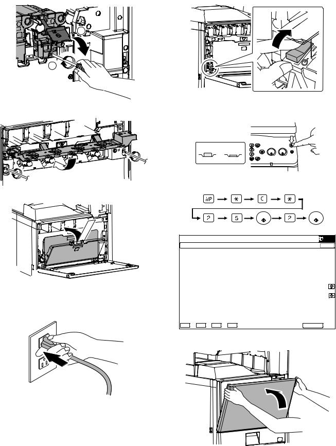
(2)Scanner (2/3 mirror unit) lock release
1)Remove the optical unit fixing screw, and remove the note label.
(3)Removal of the fusing heat roller protector
1)Open the right door.
2)Open the paper guide and pull out the fusing heat roller protector.
B. Developing (each color) installation
Be careful not to attach fingerprints or oily dirt on the DV roller surface.
1)Open the front cabinet.
2)Check that the lock is released as shown in (A).
Loosen the blue screw, and open the drum positioning unit.
*When the lock is not released, use a screwdriver to turn the screw (B) counterclockwise so that it is fit as (A).
A
 B
B
3)Open the DV lock lever, and release the fixing screw. (1position for each color)
1
2
4)Pinch the knob and remove the development unit.
5)Remove the screws.
MF 9841 MF 9626/9631/9841 1 – 4

6)Hold the sections A, and remove the DV cover in the arrow direction (B).
A
A
A
B
9)Secure the DV cover with the two screws.
7)Supply developer (package part No. 2) in the developer unit.
*Shake the bag of developer with unopened state. After stirring toner and developer in the bag, supply it to the developing unit.
*When replacing developer, use an extreme care not to drop developer on the drive section (marked with ({)).
8)Install the DV cover in the arrow direction A.
*When installing the DV cover, be sure to engage the pawl with the boss.
A
10) Shake the developer unit horizontally a few times.
* When supplying developer, do not tilt the developing unit.
11)Install each developer unit.
*When installing the developer unit, be sure to check that the DV lock lever is open.
MF 9841 MF 9626/9631/9841 1 – 5
12)Secure with fixing screw. Lower the DV lock lever until it clicks closed.
2)With the front cabinet open, turn on the power switch on the operation panel.
2 |
ON |
1
13) Close the drum positioning unit, and tighten the blue screw.
14) Install the waste toner box (package part No. 3).
3)With the front cabinet open, turn on the power switch on the operation panel.
<State of switch>
OFF ON
4)With the front cabinet still open, enter simulation 25-2.
C.Set the control level for the reference toner density
1)Insert the power plug into the power outlet.
|
|
|
|
6,08/$7,21 |
12 |
|
|
&/26( |
7(67 |
|
|
|||||
|
|
|
|
|
|
|
|
$8720$7,& '(9(/23(5$'-8670(17 |
|
|
|
||||
|
|
|
$7 '(9($'-B/B. |
$7 '(9( 92B0B. |
|
||
|
|
|
$7 '(9($'-B/B& |
$7 '(9( 92B0B& |
|
||
|
|
|
$7 '(9($'-B/B0 |
$7 '(9( 92B0B0 |
|
||
|
|
|
$7 '(9($'-B/B< |
$7 '(9( 92B0B< |
|
||
|
|
|
$7 '(9($'-B0B. |
|
|
||
|
|
|
$7 '(9($'-B0B& |
|
|
||
|
|
|
$7 '(9($'-B0B0 |
|
|
||
|
|
|
$7 '(9($'-B0B< |
|
|
||
|
|
|
$7 '(9( 92B/B. |
|
|
||
|
|
|
$7 '(9( 92B/B& |
|
|
||
|
|
|
$7 '(9( 92B/B0 |
|
|
||
|
|
|
$7 '(9( 92B/B< |
|
|
||
. |
& |
0 |
< |
(;(&87( |
|
||
5)After entering the simulation, close the front cabinet.
MF 9841 MF 9626/9631/9841 1 – 6

6)Select K, C, M, Y and then press the [EXECUTE] button. The system then performs the simulation, samples the toner density control sensor value, and sets (stores in memory) the average sensor detection level as the control level for the reference toner density. (Operating times: approx. 3 minutes)
|
|
|
|
6,08/$7,21 |
12 |
|
|
&/26( |
7(67 |
|
|
|||||
|
|
|
|
|
|
|
|
$8720$7,& '(9(/23(5$'-8670(17 |
|
|
|
||||
|
|
|
$7 '(9($'-B/B. |
$7 '(9( 92B0B. |
|
||
|
|
|
$7 '(9($'-B/B& |
$7 '(9( 92B0B& |
|
||
|
|
|
$7 '(9($'-B/B0 |
$7 '(9( 92B0B0 |
|
||
|
|
|
$7 '(9($'-B/B< |
$7 '(9( 92B0B< |
|
||
|
|
|
$7 '(9($'-B0B. |
|
|
||
|
|
|
$7 '(9($'-B0B& |
|
|
||
|
|
|
$7 '(9($'-B0B0 |
|
|
||
|
|
|
$7 '(9($'-B0B< |
|
|
||
|
|
|
$7 '(9( 92B/B. |
|
|
||
|
|
|
$7 '(9( 92B/B& |
|
|
||
|
|
|
$7 '(9( 92B/B0 |
|
|
||
|
|
|
$7 '(9( 92B/B< |
|
|
||
. |
& |
0 |
< |
(;(&87( |
|
||
Note: Be sure to select all of the four colors: K, C, M, Y
7)After the machine completes cycling, exit the simulation mode by pressing the [CA] key on the main unit.
D. Installation of individual color toner cartridges
*The life of each toner cartridge is as follows:
Black toner cartridge: equivalent to approximately 18K (A4/LT 5%)
Color toner cartridge: equivalent to approximately 15.0K (A4/LT 5%)
1)Shake the toner cartridge (package part No. 1) horizontally several times.
2)Remove the heat seal.
3)Open the front cabinet, and insert each toner cartridge.
*Be sure to install the color cartridges to their proper positions. Avoid installation to a different color position.
*Do not forcibly insert the toner cartridge.
Keep holding the cartridge and completely insert it.
*When the machine is transported with the developing unit removed, be sure to remove the toner cartridge. (If not, toner may be clogged.)
[Color toner cartridge positions]
Y M C BK
4)Insert the cartridge securely until it locks.
E. Cleaning of LSU's dust-proof glass
*Dust from the transfer belt or shutter or some other adjacent part may fall onto the LSU during transport or installation. Be sure to clean the dust-proof glass before checking the image quality.
1)Open the front cabinet.
MF 9841 MF 9626/9631/9841 1 – 7
2) Remove the waste toner box. |
6) Close the front cabinet. |
1
 2
2
3)Detach the LSU cleaning bar from the front cover.
F. Install of the paper exit tray
1) Install the paper exit tray (package part No. 4) (A) to the upper section of the right door.
Install the paper exit full detection actuator (package part No. 5) (B).
* Be careful of the direction of the paper exit full detection actuator.
4) Turn the felt side of the cleaning bar downward and insert it. |
|
B |
Slide it back and forth a few times to clean the LSU dust-proof |
B |
|
glass. |
|
|
|
|
A
5)Replace the LSU claning bar to the front cover and attach the waste toner box.
G. Installation of the paper holding arm unit
1)Install the paper holding arm unit (package part No. 6).
*If the SG-FNX3 (Inner Finisher) or the SG-BPX2 (Interface Unit) is installed when installing the main unit, do not install the paper holding arm unit and the paper exit full detection actuator.
1

 2
2
MF 9841 MF 9626/9631/9841 1 – 8

H. Installation of the operation manual pocket
1)Install the Operation Manual storage (package part No. 8) cover to the left side of the machine.
a)First, insert the pawl on the lower side of the Operation Manual pocket.
b)Then, lift the pawl on the upper side and insert it, and slide down to install.
*If the SG-FNX4 (saddle finisher) is installed together with installation of the machine, the Operation Manual storage cover must be installed to the saddle finisher.
2 |
1 |
1
I. Tray setup
(1)Simulation setup
Change the tray setting in the "system setting" mode. If "Disabling of Tray Settings" has been enabled in the system settings (administrator), the tray settings (except for the bypass tray) cannot be configured.
1)Press the [SYSTEM SETTINGS] key.
JOB STATUS |
|
|
READY |
|
DATA |
SYSTEM |
|
SETTINGS |
IMAGE SEND |
|
LINE |
|
DATA |
HOME |
|
LOGOUT
2)Touch the [Paper Tray Settings] key.
3)Touch the [Paper Tray Settings] key to configure the settings. These settings specify the paper type, paper size, and functions allowed for each paper tray. When the [Tray Settings] key is touched, a list appears showing the trays and the current settings.
4)Touch the [Change] key in the above screen to change the settings. The following settings can be configured.
Item |
Description |
Type |
Select the type of paper that is loaded in the tray. |
|
The paper types that can be selected vary by paper |
|
tray. |
Size |
Select the paper size from the list. The paper sizes |
|
that can be selected vary by tray. The sizes that |
|
can be selected may also be restricted by the paper |
|
type selected above. |
|
If the desired size does not appear in the list, select |
|
[Custom Size] and directly enter the size (only for |
|
the bypass tray). |
Feeding Approved |
Select the modes that can be used. If there is a |
Job |
function that you do not wish to be used with the |
|
selected tray, disable the function. When the "Type" |
|
is other than plain paper, recycled paper, colored |
|
paper, or a user type, [Fax] and [Internet Fax] |
|
cannot be selected. |
(2)Tray size setup
1)Pull out the paper tray.
Gently pull the tray out until it stops. If paper remains in the tray, remove it.
2)Adjust the guide plates A and B by squeezing their lock levers and sliding them to match the vertical and horizontal dimensions of the paper to be loaded.
The guide plates A and B are slidable. Slide each guide plate while squeezing its lock lever.
A
B
MF 9841 MF 9626/9631/9841 1 – 9

J. Specifications setup
Used to set the specifications with SIM26 according to the customer's request.
SIM No |
|
Content |
|
26 |
|
6 |
Used to set the destination. |
To customize the following items after completion of the destination setup, change the set values.
|
SIM No |
Content |
|
26 |
|
2 |
LCC paper size setting |
|
|
3 |
Used to set the auditor specification mode. |
|
|
5 |
Used to set the count mode of the total counter and |
|
|
|
the maintenance counter. |
|
|
52 |
Used to set YES/NO of counting when non-print |
|
|
|
paper is passed through each counter. |
|
|
53 |
Used to set YES/NO of user calibration permission. |
|
|
65 |
Used to set the limit number of sheets for stapling. |
K. Image quality check
Check the following items related to the image quality.
(1)Checking and adjustment of the image skew
1)Press [REGIST] button in SIM50-22 mode to execute the automatic image registration adjustment.
2)The current skew level is displayed on the SKEW display menu.
3)Put down the displayed skew level value.
(Meaning of the skew level value)
*When "R" is displayed in front of the value, turn and click the skew adjustment screw (LSU) clockwise by the number of the value.
*When "L" is displayed in front of the value, turn and click the skew adjustment screw (LSU) counterclockwise by the number of the value.
At that time, the fractional part after the decimal point is rounded.
NOTE: The K (black) image skew level cannot be checked with this adjustment.
To check and adjust the K (black) image skew, follow the procedures below and execute the adjustment.
1)Enter SIM61-4 mode.
|
|
|
|
7(67 6,08/$7,21 |
12 |
&/26( |
|
/68 326,7,21 $'-8670(17 6(/) 35,17 |
|||
|
$ |
|
08/7,&2817 |
|
|
||
$ |
% |
|
3$3(5 &6 |
(;(&87( 2.
|
key |
EXECUTE |
|
|
|
EXECUTE |
or end of print |
|
|
|
|
|
|
|
7(67 6,08/$7,21 |
12 |
&/26( |
|
/68 326,7,21 $'-8670(17 6(/) 35,17 |
|||
|
$ |
|
08/7,&2817 |
|
|
||
$ |
% |
|
3$3(5 &6 |
(;(&87( 2.
2)Select the paper feed tray with A3 (11" x 17") paper in it by changing the value of set item B.
3)Press [EXECUTE] key.
The check pattern is printed out.
4)Check the printed black image for any skew.
Measure the right angle level by using the six cross patterns printed in black.
There are following two methods of checking the black image for any skew (right angle).
Method 1:
Measure the length of the diagonal lines of the rectangle print pattern. Check the difference in the length of the diagonal lines for judgment of good or no good
Method 2:
Compare the right angle of vertical side/horizontal side of the rectangle print pattern and the right angle sides of A3 or 11 x 8.5 paper for judgment of good or no good.
(NOTE) In the case of Method 2, the right angle of paper to be used may not be exact. Be sure to check the right angle of paper to be used in advance.
MF 9841 MF 9626/9631/9841 1 – 10
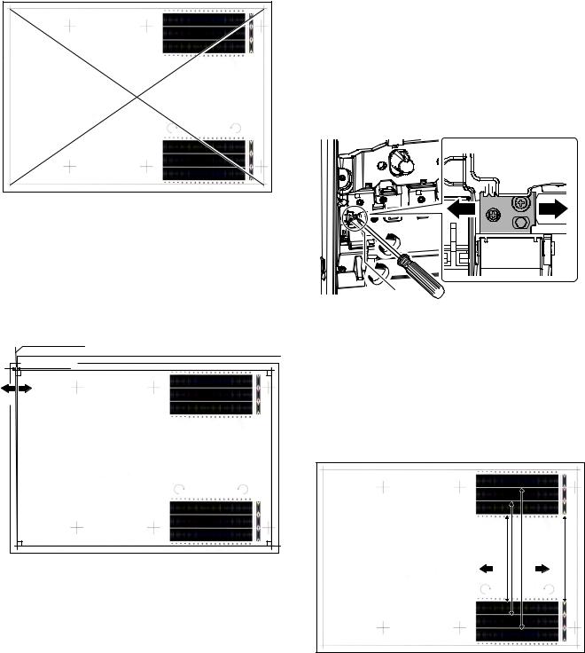
(Method 1)
a) Measure the length of the diagonal lines of the rectangle print pattern.
4
Diagonal line D
Diagonal line C
(
b)Calculate the difference between the measured lengths C and D of the diagonal lines.
c)Check to insure that the difference between C and D is in the following range. C – D = ±0.8mm
If the difference between C and D is in the above range, there is no need to adjust.
(Method 2)
a) Fit the side of A3 or 11" x 17" paper to the long side of the rectangle print pattern.
|
Comparison line |
A3 or 11 x 17 paper |
|
|
|
|
0.5mm or less |
4 |
|
|
|
Direction A |
Direction B |
|
|
|
( |
b) Measure the shift distance between vertical side of paper and side of the rectangle print pattern.
If the above distance is 0.5mm or less, there is no need to adjust.
If not, execute the following procedures.
5)Open the front cabinet, and remove the waste toner box.
6)Loosen the LSU unit fixing screws (2 pcs.) and shift the skew adjustment screw in the arrow direction to adjust the LSU (writing) unit skew.
(When Method 1 is used to check the black image for any skew (right angle) in procedure 4 in advance)
When the lengths of the diagonal line are C > D, shift the adjustment screw in the direction of Y.
When the lengths of the diagonal line are C < D, shift the adjustment screw in the direction of X.
(When Method 2 is used to check the black image for any skew (right angle) in procedure 4 in advance)
If the image is skewed in the arrow direction of A, shift the adjustment screw to X direction. If the image is skewed in the arrow direction of B, shift the adjustment screw to Y direction.
Y X
7)Install the waste toner box, and close the front cabinet.
8)Execute procedures 3) - 4).
(Repeat procedures 5) - 8) until a satisfactory result is obtained.)
9)If the adjustment result reaches the satisfactory level, tighten the adjustment screw.
(The black image skew adjustment is completed with the above.)
10)In the above black image skew adjustment, check the color image skew pattern printed when completion of the adjustment.
|
|
4 |
*B |
|
|
Yellow |
Cyan Magenta |
*A |
|
|
|
Direction A |
Direction B |
|
*B |
|
|
|
|
( |
*A: Rough adjustment print pattern *B: Fine adjustment print pattern
In each Y/M/C color print pattern printed separately in the front frame direction and in the rear frame direction, note the same print color pattern and check to confirm that the difference in the highest density sections is within ±1 step.
(Compare the front and the rear frame positions of the samecolor print color patterns. All the highest density sections of all the print color patterns may not be aligned on a line. Compare only the same-color patterns.)
If the above condition is not met, do the following:
MF 9841 MF 9626/9631/9841 1 – 11
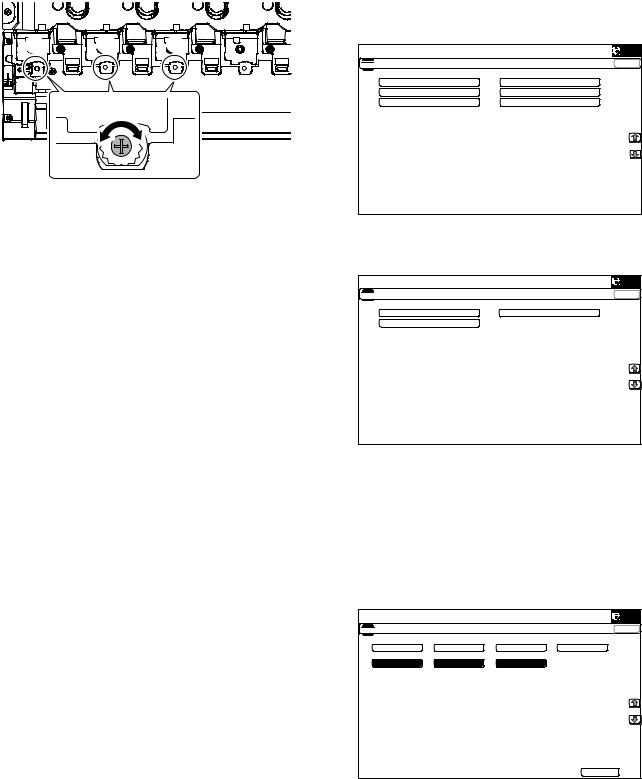
11)Turn the image skew adjustment screw of the target color to adjust.
Y M C
When each adjustment screw is turned, it clicks. Turn it by 5 - 6 clicks and the check pattern is changed by 1 step (1 dot size).
When the image skew pattern on the front frame side is skewed in the arrow direction of A (to the smaller number) from the rear frame side, turn the adjustment screw counterclockwise. When the image is skewed in the arrow direction of B (to the larger number), turn the adjustment screw clockwise.
12)Print the check pattern.
13)Check the color image skew pattern.
Repeat procedures 11) - 13) until a satisfactory result is obtained.
The image skew adjustment (LSU unit) is executed by changing the parallelism of the LSU unit scan laser beam for the OPC drum.
(2)Image registration adjustment
1)Enter SIM50-22 mode.
2)Select the adjustment target item "ALL".
ALL:
Image registration (Auto adjustment of the main scanning direction, the sub scanning direction and the OPC drum phase)
3)Press [EXECUTE] key.
The adjustment are executed automatically and adjustment result data is displayed.
4)Check the image registration.
NOTE: For details of the checking procedures of the image registration, refer to the ADJ10B and the ADJ10C.
(3)Image loss, void area, image off-center adjustment
Make a copy in the original table mode and in the RSPF/DSPF mode. Check to confirm that the image loss and the void area are in the range shown below.
Content |
Standard adjustment value |
Lead edge void area |
3.0±1.0mm |
Rear edge void area |
2.0 - 5.0mm |
FRONT/REAR void area |
2.0±2.0mm |
Lead edge image loss adjustment |
3.0±1.0mm |
Side image loss adjustment |
2.0±1.0mm |
NOTE: For details of the checking procedures of the image loss and the void area, refer to the ADJ17 and the ADJ18.
(Adjustment procedure)
a.Image off-center automatic adjustment (in original table mode)
1) Enter the SIM50-28 mode. |
|
|
|
|
|
|
|
7(67 6,08/$7,21 |
12 |
|
&/26( |
$872 ,0$*( 326,7,21 $'-8670(17 6(59,&( |
|
|
|
|
2& $'- |
%. 0$* $'- |
|
|
63) $'- |
6(783 35,17 |
$'- |
|
5(68/7 |
'$7$ |
|
|
|
|
|
2)Select [SETUP/PRINT] ADJ with the key button.
3)Select [ALL] with the key button.
|
|
|
7(67 6,08/$7,21 |
12 |
&/26( |
$872 ,0$*( 326,7,21 $'-8670(17 6(59,&( |
|
|
|
/($' |
2))6(7 |
|
$// |
|
|
|
|
(Note) |
|
|
By pressing [LEAD] or [OFFSET] button, the following items can be executed individually.
*[LEAD]: Print image lead edge image position adjustment
*[OFFSET]: Print image off-center adjustment
When [ALL] is selected, both of the above two items are executed simultaneously.
4)Select a paper feed tray to be adjusted. (Select all of paper feed trays.)
|
|
|
|
|
7(67 6,08/$7,21 |
12 |
|
|
&/26( |
$872 ,0$*( 326,7,21 $'-8670(17 6(59,&( |
|
|
|
|
0)7 |
&6 |
&6 |
$'8 |
|
&6 |
&6 |
/&& |
|
|
|
|
|
(;(&87( |
|
5)Press [EXECUTE] key.
The adjustment pattern is printed out.
(Each paper is fed from selected paper feed tray, and the individual pattern according to each paper feed tray is printed out.)
MF 9841 MF 9626/9631/9841 1 – 12

6)Set the adjustment pattern on the document table. (Any direction)
NOTE: Fit the adjustment pattern correctly with the document guide.
7)Press [EXECUTE] key.
The following item is automatically adjustment.
*Print image lead edge image position adjustment
*Print image off-center adjustment
Perform procedures 6) to 7) for adjustment patterns output from each paper feed tray.
8)Press [OK] key.
The adjustment result becomes valid.
Perform procedures 4) to 7) for each paper feed tray.
b.Copy lead edge image reference position adjustment, image off-center, and sub scanning direction image magnification ratio automatic adjustment. (in original table mode)
1) Enter the SIM50-28 mode. |
|
|
|
|
|
|
|
7(67 6,08/$7,21 |
12 |
|
&/26( |
$872 ,0$*( 326,7,21 $'-8670(17 6(59,&( |
|
|
|
|
2& $'- |
%. 0$* $'- |
|
|
63) $'- |
6(783 35,17 |
$'- |
|
5(68/7 |
'$7$ |
|
|
|
|
|
2)Select [OC ADJ] with the key button.
3)Select the paper feed tray with paper in it with the key button. (Any paper size will do.)
|
|
|
|
7(67 6,08/$7,21 |
12 |
|
&/26( |
$872 ,0$*( 326,7,21 $'-8670(17 6(59,&( |
|
|
|
0)7 |
&6 |
&6 |
|
|
|
(;(&87( |
|
4)Press [EXECUTE] key.
The color patch image (adjustment pattern) is printed out.
5)Set the adjustment pattern on the document table. (Any direction)
NOTE: Fit the adjustment pattern correctly with the document guide.
6)Press [EXECUTE] key.
|
|
6,08/$7,21 12 |
|
|
|
&/26( |
|
|
|
||
|
7(67 |
$872 ,0$*( 326,7,21 $'-8670(17 6(59,&( 3/($6( :$,7
12: (;(&87,1*
5(35,17 |
(;(&87( |
The following item is automatically adjustment.
*Copy lead edge image reference position adjustment, image off-center, sub scanning direction image magnification ratio automatic adjustment
7)Press [OK] key.
The adjustment result becomes valid.
|
|
6,08/$7,21 12 |
|
|
|
&/26( |
|
|
|
||
|
7(67 |
$872 ,0$*( 326,7,21 $'-8670(17 6(59,&( 6,08/$7,21 &203/(7(
3/($6( 386+ &$ .(<
MF 9841 MF 9626/9631/9841 1 – 13

c.Auto adjustment in RSPF mode of the image off-center, image lead edge and image magnification in the subscanning direction
1) Enter the SIM50-28 mode. |
|
|
|
|
|
|
|
7(67 6,08/$7,21 |
12 |
|
&/26( |
$872 ,0$*( 326,7,21 $'-8670(17 6(59,&( |
|
|
|
|
2& $'- |
%. 0$* $'- |
|
|
63) $'- |
6(783 35,17 |
$'- |
|
5(68/7 |
'$7$ |
|
|
|
|
|
2)Press the [SPF ADJ] button.
|
|
|
7(67 6,08/$7,21 |
12 |
&/26( |
$872 ,0$*( 326,7,21 $'-8670(17 6(59,&( |
|
|
|
6,'( |
6,'( |
|
$// |
|
|
|
|
3)Select [ALL] key.
4)Select one of the paper feed trays that can be used to print RSPF adjustment patterns. (Multiple selection is not allowed.)
5)Press the [EXECUTE] button, and the machine starts self-print of SPF adjustment patterns.
*The screen shows a message indicating that the machine is self-printing SPF adjustment patterns.
When self-print finishes, the next screen appears where you can start SPF adjustments.
6)Set up the RSPF adjustment patterns on the RSPF with pattern side up.
*By pressing the [REPRINT] button, you can return to the cassette selection screen and have the machine self-print RSPF adjustment patterns again.
7)Press the [EXECUTE] button, and the machine starts reading SPF adjustment patterns (for the front side).
*The machine starts calculating the adjustment amount (for the front side) after it has read the patterns for the front side.
After the machine has finished calculating the adjustment amount for the front side, the next screen appears where you can have the machine start reading SPF adjustment patterns (for the back side).
8)Set up the RSPF adjustment patterns on the RSPF with blank side up.
*By pressing the [REPRINT] button, you can return to the cassette selection screen and have the machine self-print SPF adjustment patterns again.
9)Press the [EXECUTE] button. The machine starts scanning RSPF adjustment patterns (for the back side).
The adjustment result screen appears.
10)press the [OK] button. The adjustment values are saved into EEPROM and RAM and return to the top menu.
*To return to the result screen, press the [BACK] button.
d.Auto adjustment in DSPF mode of the image off-center, image lead edge and image magnification in the subscanning direction
1)Enter the simulation mode 50-28.
|
|
|
6,08/$7,21 |
12 |
|
&/26( |
|
7(67 |
|
|||||
|
|
|
|
|
||
$872 ,0$*( 326,7,21 $'-8670(17 6(59,&( |
|
|
||||
|
|
|
2& $'- |
%. 0$* $'- |
||
|
|
|
63) |
$'- |
6(783 35,17 |
$'- |
|
|
|
5(68/7 |
'$7$ |
|
|
2)Press [SPF ADJ] key.
3)Select [ALL] key.
<List of adjustment items>
Menu display item |
Content |
SIDE1 |
SPF adjustment front surface |
SIDE2 |
SPF adjustment back surface |
ALL |
SPF adjustment front/back surface |
MF 9841 MF 9626/9631/9841 1 – 14

|
|
6,08/$7,21 |
12 |
&/26( |
7(67 |
|||
$872 ,0$*( 326,7,21 $'-8670(17 6(59,&( |
|
||
|
|
6,'( |
6,'( |
|
|
$// |
|
4)The display shows the tray select screen for printing the DSPF adjustment pattern. Select a paper feed tray for DSPF adjustment printing.
|
|
|
6,08/$7,21 |
12 |
&/26( |
7(67 |
||||
|
|
|
|
|
$872 ,0$*( 326,7,21 $'-8670(17 6(59,&( |
|
|||
0)7 |
&6 |
&6 |
||
(;(&87(
5)Press [EXECUTE] key. Self-print of the DSPF adjustment pattern is performed.
After completion of printing, the DSPF adjustment start screen is displayed.
|
|
|
6,08/$7,21 |
12 |
&/26( |
7(67 |
||||
$872 ,0$*( 326,7,21 $'-8670(17 6(59,&( 12: (;(&87,1*
(;(&87(
|
7(67 6,08/$7,21 12 &/26(
$872 ,0$*( 326,7,21 $'-8670(17 6(59,&( 3/($6( 6(7 7+( 35,17(5 3$77(51 3$3(5 21 7+( 63)
7+(1 35(66 >(;(&87(@ 72 67$57
5(35,17 |
(;(&87( |
6)Set up the DSPF adjustment patterns on the DSPF with pattern side up.
7)Press [EXECUTE] key. Scanning of the DSPF adjustment pattern is started.
|
|
|
6,08/$7,21 |
12 |
&/26( |
7(67 |
||||
$872 ,0$*( 326,7,21 $'-8670(17 6(59,&( 3/($6( :$,7
12: (;8&87,1*
5(35,17 |
(;(&87( |
8)Set up the DSPF adjustment patterns on the DSPF with blank side up.
9)Press [EXECUTE] key.
Scanning of the DSPF adjustment pattern is started.
10)The adjustment result screen is displayed.
|
7(67 6,08/$7,21 12 &/26(
$872 ,0$*( 326,7,21 $'-8670(17 6(59,&( 63) 6,'( /($' 2))6(7 68%
63) 6,'( /($' 2))6(7 68%
5(35,17 |
5(6&$1 |
5(75< |
'$7$ |
2. |
11)Press [OK] key. The adjustment value is saved in EEPROM and RAM and the display is shifted to the end screen.
|
7(67 6,08/$7,21 12 &/26(
$872 ,0$*( 326,7,21 $'-8670(17 6(59,&( 6,08/$7,21 &203/(7(
3/($6( 386+ &$ .(<
MF 9841 MF 9626/9631/9841 1 – 15

(4)Copy/Printer color balance density adjustment (Auto adjustment)
a.Note for execution of the color balance adjustment (Auto adjustment)
• Be sure to use the recommended paper for color. b. Adjustment procedure
1)Enter the SIM46-74 mode.
|
|
6,08/$7,21 12 |
|
|
|
&/26( |
|
|
|
||
7(67 |
|||
(1*,1( $872 $'-8670(17 6(59,&( 35(66 >(;(&87(@ 72 352&21 (;(&87,21 $1' 35,17 7+( 7(67 3$7&+
3/($6( 86( 63(&,),(' 7<3( 2) $ 25 6,=( 3$3(5
)25 7+,6 $'-8670(17
(;(&87(
2)Press [EXECUTE] key.
The high density process control is performed, and the copy color patch image (adjustment pattern) is printed out. (A3 or 11" x 17" paper is automatically selected.)
|
|
6,08/$7,21 |
12 |
|
|
|
&/26( |
||
|
|
|||
|
7(67 |
|||
(1*,1( $872 $'-8670(17 6(59,&( |
|
|||
352&21 (;(&87,1* |
|
|||
(;(&87(
3)Set the color patch image (adjustment pattern) paper printed in procedure 2) on the document table.
Place the color patch image so that the fine lines are on the left side. At that time, place 5 sheets of white paper on the printed color patch image (adjustment pattern).
4)Press [FACTORY] key on the operation panel, and press [EXECUTE] key.
|
|
6,08/$7,21 12 |
|
|
|
&/26( |
|
|
|
||
7(67 |
|||
(1*,1( $872 $'-8670(17 6(59,&( 3/($6( 6(/(&7 7+( 02'( )$&725< 25 6(59,&( $1' 3/$&(
7+( 35,17(' 7(67 3$7&+ 21 '2&80(17 */$66 7+(1 35(66 >(;(&87(@
/,*+7 $5($ $7 /()7 6,'( 21 '2&80(17 */$66
)$&725< |
6(59,&( |
(;(&87( |
The copy color balance adjustment is automatically executed and prints the color balance check patch image.
If there is any streak or unclear print on the printed check pattern, check the print engine for any problems.
Low density 
 High density


 ;
;


 /
/


 %
%


 $M
$M
3
/CZ
#$ % & ' ( ) * + , - . / 0 1 2
Remark:
(Descriptions on the factory service key button in the color balance automatic adjustment menu)
There are two kinds of the gamma target for the color balance automatic adjustment: the factory target and the service target.
FACTORY key and SERVICE key are used to select one of the above two.
Factory target color balance: Standard color balance
(The color balance can be selected from the three kinds of fixed ones with SIM63-11.)
Service target color balance: The color balance can be customized according to the user's request. (Variable)
When shipping from the factory, the service target gamma data and the factory target gamma data are the same.
Both are set to the standard color balance when shipping from the factory. For the service target, a customized color balance gamma can be registered with SIM63-7.
MF 9841 MF 9626/9631/9841 1 – 16

5)Press [EXECUTE] key.
The printer color patch image (adjustment pattern) is printed out. (A3 or 11" x 17" paper is automatically selected.
|
|
6,08/$7,21 |
12 |
|
|
|
|
&/26( |
|||
|
|
||||
|
7(67 |
||||
|
|
|
|
|
|
(1*,1( $872 $'-8670(17 6(59,&( |
|
|
|||
&21),50 7+( $'- 3$7&+ $1' 35(66 >(;(&87(@ 72 $'- 2) 5(*,675 |
$7,21 (;( |
|
|||
$1' 35,17 7+( 7(67 3$7&+ |
|
|
|||
3/($6( 86( 63(&,),(' 7<3( 2) $ 25 6,=( 3$3(5 |
|
|
|||
)25 7+,6 $'-8670(17 |
|
|
|||
(;(&87(
6)Set the color patch image (adjustment pattern) printed in the procedure 5) on the document table.
Place the color patch image so that the fine lines are on the left side. At that time, place 5 sheets of white paper on the printed color patch image (adjustment pattern).
PRINTER CALIBRATION
7)Press [FACTORY] key on the operation panel, and press [EXECUTE] key.
|
|
6,08/$7,21 |
12 |
|
|
|
|
&/26( |
|||
|
|
||||
|
7(67 |
||||
(1*,1( $872 $'-8670(17 6(59,&( |
|
|
|||
3/($6( :$,7 |
|
|
|||
12: 5(*,67(5,1* 7+( 1(: 7 |
$5*(7 2) +$/)721( 352&21 67 |
|
|||
2.
The printer color balance adjustment (step 1) is automatically performed and the color balance check patch image is printed out.
If there is any streak or unclear print on the printed check pattern, check the print engine for any problems.
Low density 
 High density


 ;
;


 /
/


 %
%


 $M
$M
3  /CZ
/CZ
# $ % & ' ( ) * + , - . / 0 1 2
8)The initial setting menu of the half tone image correction is displayed. Press [OK] key.
The initial setting of the half tone image correction is performed.
|
|
6,08/$7,21 |
12 |
|
|
|
|
|
|
|
|
&/26( |
|||
|
|
|
|
||||
|
7(67 |
|
|
||||
|
|
|
|
|
|
||
(1*,1( $872 $'-8670(17 6(59,&( |
|
|
|
||||
&21),50 7+( $'-867(' 3 |
$7&+ $1' 35(66 >2.@ 72 5(*,67(5 7+,6 3 |
$7&+ '$7 |
$ |
|
|||
|
|
|
|
|
|
||
2.
9)When "COMPLETE THIS PROCEDURE" is displayed, the adjustment operation is completed. Cancel the simulation 4674 by pressing the [CA] Key.
|
|
|
6,08/$7,21 12 |
|
|
|
|
&/26( |
|
|
|
|
||
7(67 |
|
|||
(1*,1( $872 $'-8670(17 6(59,&( &203/(7(' 7+,6 352&('85(
3/($6( 48,7 7+,6 02'(
NOTE: The adjustment result becomes valid only when the both adjustments in the copy mode and in the printer mode are completed.
For example, if the copy color balance adjustment (automatic adjustment) is performed and the simulation is canceled, the adjustment result is invalid.
MF 9841 MF 9626/9631/9841 1 – 17
10)Check the copy color balance and density.
There are two methods to check the color balance and density. (Method 1)
Use the servicing color test chart (UKOG-0317FCZZ/UKOG- 0317FC11) in the Text/Printed Photo mode (Manual) to check the copy color balance and density. (Refer to the item of the copy color balance and density check.)
(Method 2)
By printing the color balance adjustment sheet with SIM 46-21 and comparing each process (CMY) black patch color balance with the black patch, the color balance adjustment can be checked more precisely.
Low density 
 High density


 ;
; 


 /
/ 


 %
% 


 $M
$M
CMY
Blend
3
/CZ
# $ % & ' ( ) * + , - . / 0 1 2
2)Patch C or D of each of Y, C, M, and BK is very slightly copied.
Patch A of each of Y, M, C, and
BK are not copied.
1)The max. density section is not blurred.
3)Patch for each of C, M, Y, BK
 The patch density is identical between patches or not reversed.
 The patch density is changed gradually.
If the color balance of each patch of the process black (CMY mixed color) is slightly shifted to Magenta, it means that the adjustment is proper. If the color balance of the adjustment pattern printed in this mode is slightly shifted to Magenta, it is converted into the natural gray color balance by the color correction table in an actual copy mode. (When the color balance target is DEF 1.)
If the automatic adjustment cannot obtain satisfactory results of the copy color balance and density, use SIM 46-21 (ADJ 20C) (Manual adjustment).
11)Check the printer color balance and density.
There are two methods to check the color balance and density. (Method 1)
Use SIM 64-5 to print the print test pattern and check the print color balance and the density.
Set each setting value to the default and press [EXECUTE] key, and the print test pattern is printed.
(Refer to the item of the printer color balance and density check.)
(Method 2)
Use SIM67-25 to print the color balance adjustment sheet and compare the black patch color balance of each process (CMY) with the black patch. This procedure allows checking the color balance adjustment result correctly.
Low density 
 High density


 ;
; 


 /
/ 


 %
% 


 $M
$M
CMY
Blend
3
/CZ
# $ % & ' ( ) * + , - . / 0 1 2
2)Patch C or D of each of Y, C, M, and BK is very slightly copied.
Patch A of each of Y, M, C, and
BK are not copied.
1)The max. density section is not blurred.
3)Patch for each of C, M, Y, BK
 The patch density is identical between patches or not reversed.
 The patch density is changed gradually.
If the color balance of each patch of the process black (CMY mixed color) is slightly shifted to Magenta, it means that the adjustment is proper. If the color balance of the adjustment pattern printed in this mode is slightly shifted to Magenta, it is converted into the natural gray color balance by the color table in an actual printer mode. (When the color balance target is DEF 1.)
If a satisfactory result on the print color balance and the density is not obtained with the automatic adjustment, execute the manual adjustment (SIM 67-25) (ADJ 21B).
L. Function and operation check
Check that the following operations are normal.
Check item list |
Equipped condition |
||
Key-in (operation panel) |
|
||
Display (operation panel) |
|
||
Paper feed |
|
Hand feed |
|
operation |
|
Main unit paper |
|
|
|
tray |
|
|
|
Desk unit paper |
With the desk unit installed |
|
|
feed tray |
|
Paper size detection |
|
|
|
Originals size |
|
Original table |
|
detection |
|
mode |
|
|
|
RSPF mode |
|
RSPF operation/ |
|
S-S mode |
|
two sided copy |
|
D-S mode |
|
|
|
S-D mode |
|
|
|
D-D mode |
|
Bookbinding operation |
When the finisher is installed |
||
Stapling operation |
|
When the finisher is installed |
|
Grouping operation |
|
When the finisher is installed |
|
Sorting operation |
|
When the finisher is installed |
|
MF 9841 MF 9626/9631/9841 1 – 18
M. Setup and adjustment data recording
Print the various setup data and the adjustment data (list) with SIM22-6 and keep the data.
•In case of a memory trouble, if the data are not kept, all the adjustments must be made again.
•If the data are kept, the setup values and the adjustment values can be entered without adjustments, shortening the servicing time.
N. Necessary works before moving the machine
1)If the following options are installed, remove all of them from the machine.
•Saddle stitch finisher
•Large capacity tray
2)Remove the following consumable parts from the machine.
•Paper
•Toner cartridges
•Development cartridge
3)Lock the following sections.
•Scanner (Optical section)
•Paper cassette lift plate
NOTE: Since the hard disk drive is built in the machine, use care not to exert vibrations or shocks to the machine when in transit.
MF 9841 MF 9626/9631/9841 1 – 19

[2] SG-CPX4/CPX6
1.Unpacking
A. Removal of the desk unit
B.Removal of the fixing material and packing parts
*If the connector is removed first, it may be pinched in the installing procedures. Therefore, keep it packed when unpacking the package, and unpack it when connecting the connector to the machine.
1)Remove the fixing material and packing parts.
C. Check the packed items
1)Check that all the items are included in the package.
|
1 |
2 |
|
|
|
|
|
No. |
Names of bundles |
|
Quantity |
1 |
Right adjuster |
|
1 |
2 |
Fixing screws (M4 x 8) |
|
4 |
2.Installation
<Note before installation>
*Before starting installation, check to insure that the data lamp on the operation panel does not light up or blink.
A. Turn off the power of the main unit
1)Turn OFF the power switch on the operation panel.
<State of switch>
OFF ON
2)Open the front cabinet.
Turn OFF the power switch in the front cabinet of the main unit.
OFF
3)Disconnect the power plug of the main unit from the power outlet.
MF 9841 SG-CPX4/CPX6 2 – 1

B. Installation of the adjuster
1)Install the right adjuster (package part No. 1) to the desk unit.
2)Turn each adjuster to fix the desk unit.
2)Put the main unit on the desk unit.
*Use man power of four persons or more to lift the main unit.
*Place the main unit on the desk unit slowly by fitting the external lines. Check to insure that the positioning pin on the top of the desk unit is securely engaged in the positioning groove of the main unit.
C. Connection of the main unit and the desk unit
1)Remove the connection plate covers of the both sides of the
main unit.
3) Remove the No. 2 paper feed tray.
2
 2
2
1
1
4) Pull out the No. 3 paper feed tray until it stops.
2 
1
MF 9841 SG-CPX4/CPX6 2 – 2

5)Lift the connection plates on the right and left of the main unit front side, and fix them with the fixing screws (package part No. 2).
6)Replace the No. 3 and No. 2 trays to the original positions.
1
2
7)Lift the connection plates, and fix them with the fixing screws.
8)Install the connection plate covers.
2
1
2
 1
1
MF 9841 SG-CPX4/CPX6 2 – 3

D. Release the lock
1)Pull out each tray.
2)Turn and remove the fixing material, and remove the caution sheet.
3)Attach the removed fixing material to the position shown in the figure for storage.
NOTE:
Before turning on the power, check to insure that the fixing material of the tray is disengaged. If the power is turned on without disengaging the fixing material, a trouble may be resulted.
4)Close the cassette which was pulled out.
E. Connector connection
1)Remove the screw from the back of the main unit. Remove the connector cover.
2)Connect the connector.
3)Split the removed connector cover along the perforated line.
4)Install the connector cover and fix it with a screw.
MF 9841 SG-CPX4/CPX6 2 – 4
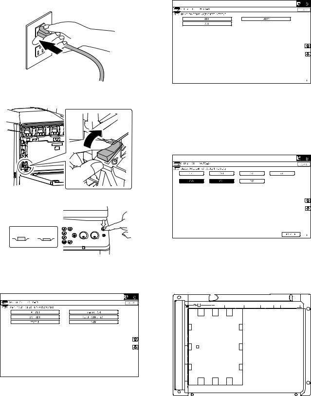
F. Turn on the power of the main unit
1)Insert the power plug of the main unit into the power outlet.
2)Open the front cabinet.
Turn ON the power switch in the front cabinet of the main unit.
ON
3)Turn ON the power switch on the operation panel.
<State of switch>
OFF ON
* For setting the tray size, refer to "Tray size setting" (1-9).
G. Image off-center adjustment
1) Enter the SIM50-28 mode. |
2)Select [SETUP/PRINT] ADJ with the key button.
3)Select [ALL] with the key button.
(Note)
By pressing [LEAD] or [OFFSET] button, the following items can be executed individually.
*[LEAD]: Print image lead edge image position adjustment
*[OFFSET]: Print image off-center adjustment
When [ALL] is selected, both of the above two items are executed simultaneously.
4)Select a paper feed tray to be adjusted.
5)Press [EXECUTE] key.
The color patch image (adjustment pattern) is printed out.
6)Set the adjustment pattern on the document table. (Any direction)
NOTE: Fit the adjustment pattern correctly with the document guide.
7)Press [EXECUTE] key.
The following item is automatically adjustment.
*Print image lead edge image position adjustment
*Print image off-center adjustment
8)Press [OK] key.
The adjustment result becomes valid.
Perform procedures 4) to 7) for each paper feed tray.
MF 9841 SG-CPX4/CPX6 2 – 5
Loading...