


MF9500
30000113482-01
Printer Manual
S
INSTALLATION REQUIREMENTS
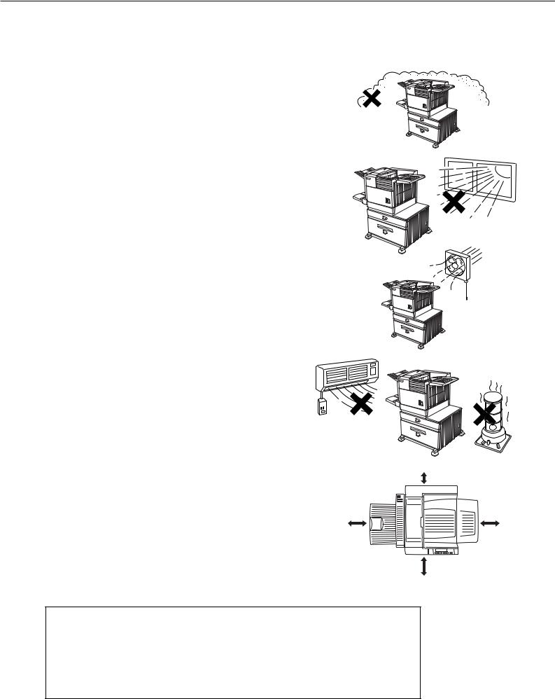
Improper installation may damage this product. Please note the following during initial installation and whenever the machine is moved.
1. The machine should be installed near an accessible power outlet for easy connection.
2. Be sure to connect the power cord only to a power outlet that meets the specified voltage and current requirements. Also make certain the outlet is properly grounded.
● For the power supply requirements, see the name plate of the main unit.
3. Do not install your machine in areas that are: ● damp, humid, or very dusty
● exposed to direct sunlight
●poorly ventilated
●subject to extreme temperature or humidity
changes, e.g., near an air conditioner or heater.
4. Be sure to allow the required space around the machine for servicing and proper ventilation.
|
11-13/16" (30cm) |
31-1/2" |
23-5/8" |
(80cm) |
(60cm) |
23-5/8" (60cm)
A small amount of ozone is produced within the printer during operation. The emission level is insufficient to cause any health hazard.
NOTE:
The present recommended long term exposure limit for ozone is 0.1 ppm (0.2 mg/m3) calculated as an 8 hr. time-weighted average concentration.
However, since the small amount that is emitted may have an objectionable odor, it is advisable to place the copier in a ventilated area.
0 - 1

INSTALLATION REQUIREMENTS
Moving this machine
Lift this machine at the positions shown in the illustration below and carry it horizontally.
CAUTION
Two people are required to lift and carry this machine.
The center of gravity of the machine is slightly to the left of the center of the machine when viewed from the front. If a duplex module is installed the center of gravity will be even further shifted to the left. When lifting the machine be careful to steady it to prevent it from toppling. Also be sure that all covers and the duplex module are securely closed and latched before lifting.
If a duplex module is installed, do not lift the machine by the module as it may come off causing it and the machine to drop.
Lift at the positions shown in the illustration.
Front side |
Rear side |
Remove the multi purpose drawer in advance.
If the machine has been placed on a stand/paper drawer:
The stand/paper drawer is equipped with casters for moving. Unlock the adjusters of the stand/paper drawer and gently move the machine taking care to steady it to prevent it from toppling.
For locking and unlocking the adjusters, see page 0-3.
CAUTIONS
●The center of gravity of this machine is a little deviated to the left from the center. If the machine is not equipped with a stand/paper drawer, take care in opening the left side cover (or the duplex module) not to cause toppling of the machine.
●Do not cover the ventilating holes of this machine. Do not install this machine in a location where these holes are covered. If these holes are covered, heat will not be dissipated and a fire may be caused.
Ventilating holes
0 - 2

CAUTIONS
1.Do not touch the photoconductive drum. Scratches or smudges on the drum will cause dirty prints.
2.The fusing unit is extremely hot. Exercise care in this area.
3.Do not look directly at the light source of the scanner module. Doing so may damage your eyes.
4.Five adjusters are provided on all optional stand/ paper drawer units. These adjusters should be lowered until they contact the floor.
5.Do not make any modifications to this machine. Doing so may result in personal injury or damage to the machine.
6.Since this machine is heavy, it is recommended that it be moved by more than one person to prevent injury.
7.When connecting this machine to a computer, be sure to first turn both the computer and the machine off.
8.Do not print anything which is prohibited from printing by law. The following items are normally prohibited from printing by national law. Other items may be prohibited by local law.
● Money ● Stamps ● Bonds ● Stocks ● Bank drafts ● Checks ● Passports
● Driver's licenses
9.Do not throw toner or a toner cartridge into fire. Toner may be spattered, causing a burn.
NOTE
This is a class A product. In a domestic environment this product may cause radio interference in which case the user may be required to take adequate measures.
Fusing unit
Adjuster
Lock 
 Release
0 - 3

CAUTIONS
Cautions on laser
Wave length |
785 nm +10 nm |
|
|
−15 nm |
|
|
|
|
Pulse times |
North America: |
35 cpm model: (4.1 µs ± 4.1 ns)/7 mm |
|
|
45 cpm model: (5.7 µs ± 5.7 ns)/7 mm |
|
Europe: |
31 cpm model: (3.8 µs ± 3.8 ns)/7 mm |
|
|
35 cpm model: (3.8 µs ± 3.8 ns)/7 mm |
|
|
45 cpm model: (4.4 µs ± 4.4 ns)/7 mm |
|
|
|
Output power |
0.2 mW - 0.4 mW |
|
|
|
|
At the production line, the output power of the scanner unit is adjusted to 0.4
MILLIWATT PLUS 8 % and is maintained constant by the operation of the Automatic
Power Control (APC).
Caution
This product contains a low power laser device. To ensure safety do not remove any cover or attempt to gain access to the inside of the product. Refer all servicing to qualified personnel.
For North America:
SAFETY PRECAUTIONS
This Digital Equipment is rated Class 1 and complies with 21 CFR 1040.10 and 1040.11 of the CDRH standards. This means that the equipment does not produce hazardous laser radiation. For your safety, observe the precautions below.
●Do not remove the cabinet, operation panel or any other covers.
●The equipment's exterior covers contain several safety interlock switches. Do not bypass any safety interlock by inserting wedges or other items into switch slots.
Caution
Use of controls or adjustments or performance of procedures other than those specified herein may result in hazardous radiation exposure.
0 - 4

CAUTIONS
For Europe:
|
|
CAUTION |
VAROITUS! |
|
|
|
INVISIBLE LASER RADIATION |
LAITTEEN KÄYTTÄMINEN |
|
|
|
WHEN OPEN INTERLOCKS |
MUULLA KUIN TÄSSÄ |
|
CLASS 1 LASER PRODUCT |
||||
|
DEFEATED. AVOID EXPOSURE |
KÄYTTÖOHJEESSA |
||
|
|
TO BEAM. |
MAINITULLA TAVALLA SAATTAA |
|
|
||||
|
|
VORSICHT |
ALTISTAA KÄYTTÄJÄN |
|
LASER KLASSE 1 |
|
|||
|
TURVALLISUUSLUOKAN 1 |
|||
|
UNSICHTBARE |
|||
|
|
YLITTÄVÄLLE |
||
|
|
LASERSTRAHLUNG WENN |
||
|
|
NÄKYMÄTTÖMÄLLE |
||
LUOKAN 1 LASERLAITE |
|
ABDECKUNG GEÖFFNET UND |
||
|
LASERSÄTEILYLLE. |
|||
|
SICHERHEITSVERRIEGELUNG |
|||
|
|
|
||
|
|
ÜBERBRÜCKT. NICHT DEM |
VARNING |
|
|
|
STRAHL AUSSETZEN. |
||
KLASS 1 LASERAPPARAT |
|
OM APPARATEN ANVÄNDS PÅ |
||
|
|
|||
|
|
ADVARSEL |
ANNAT SÄTT ÄN I DENNA |
|
|
||||
|
|
USYNLIG LASERSTRÅLNING |
BRUKSANVISNING |
|
|
|
VED ÅBNING, NÅR |
SPECIFICERATS, KAN |
|
|
|
SIKKERHEDSBRYDERE ER |
ANVÄNDAREN UTSÄTTAS FÖR |
|
|
|
UDE AF FUNKTION. UNDGÅ |
OSYNLIG LASERSTRÅLNING, |
|
|
|
UDSAETTELSE FOR |
SOM ÖVERSKRIDER GRÄNSEN |
|
|
|
STRÅLNING. |
FÖR LASERKLASS 1. |
|
|
|
|
|
|
|
|
|
|
|
|
|
CAUTION |
AVOID EXPOSURE TO BEAM. |
|
|
|||||
|
|
|
|
|
|
|
|
|
|
INVISIBLE LASER RADIATION WHEN OPEN AND INTERLOCKS DEFEATED. |
|
|
||||
|
|
|
|
|
|
|
|
VORSICHT |
UNSICHTBARE LASERSTRAHLUNG WENN ABDECKUNG GEÖFFNET UND |
|
|
|||||
|
|
|
|
|
|
|
|
ADVARSEL |
SICHERHEITSVERRIEGELUNG ÜBERERÜCKT. NICHT DEM STRAHL AUSSETZEN. |
|
|
|||||
|
|
|
|
|
|
|
|
UDE AF FUNKTION. UNDGÅ UDSAETTELSE FOR STRÅLNING. |
|
|
||||||
|
|
|
|
|
|
|
|
ADVERSEL |
USYNLIG LASERSTRÅLING VED ÅBNING, NÅR SIKKERHEDSAFBRYDERE ER |
|
|
|||||
|
|
|
|
|
|
|
|
UNNGÅ EKSPONERING FOR STRÅLEN. |
|
|
||||||
|
|
|
|
|
|
|
|
VARNING |
|
USYNLIG LASERSTRÅLING NÅR DEKSEL ÅPNES OG SIKKERHEDSLÅS BRYTES. |
|
|
||||
|
|
|
|
|
|
|
|
OSYNLIG LASERSTRÅLNING NÄR DENNA DEL ÄR ÖPPNAD OCH SPÄRRAR ÄR |
|
|
||||||
|
|
Laserstrahl |
|
|
|
|
VARO! |
|
URKOPPLADE. STRÅLEN ÄR FARLIG. BETRAKTA EJ STRÅLEN. |
|
|
|||||
|
|
|
|
|
|
AVATTAESSA JA SUOJALUKITUS OHITETTAESSA OLET ALTTIINA NÄKYMÄTÖNTÄ |
|
|
||||||||
|
|
|
|
|
|
|
|
LASERSÄTEILYLLE. ÄLÄ KATSO SÄTEESEEN. |
|
|
||||||
|
|
|
|
|
|
|
|
|
|
|
||||||
|
|
|
|
|
|
|
|
|
|
|
|
|
|
|
|
|
|
|
|
|
|
|
|
|
|
|
|
|
|
|
|
|
|
|
|
|
|
|
|
|
|
|
|
|
|
|
|
|
|
|
|
|
|
|
|
|
|
|
|
|
|
|
|
|
|
|
|
|
|
|
|
|
|
|
|
|
|
|
|
|
|
|
|
|
|
|
|
|
|
|
|
|
|
|
|
|
|
|
|
|
|
|
|
|
|
|
|
|
|
|
|
|
|
|
|
|
|
|
CLASS 1
LASER PRODUCT
LASER KLASSE 1
0 - 5

FACSIMILE FEATURE
To extend the capabilities of this product to include facsimile functions, an optional facsimile expansion kit must be installed. Refer to the facsimile operation manual for details on using the facsimile features.
■ Line connection
Use the telephone cable supplied with the facsimile expansion kit to connect the machine to a telephone line. Connect the cable so that the connector nearest to the noise suppression core is inserted into the socket located of the expansion kit box. Insert the other end into the telephone line socket.
Line connector
TEL
LINE
Core
■ Fax power switch
For the facsimile features to function, the power switch located on the expansion kit box must be turned on.
TEL
LINE
Fax power switch
ON
OFF
0 - 6

CONTENTS
Page INSTALLATION REQUIREMENTS . . . . . . . . . . . 0-1 ● Carrying this machine . . . . . . . . . . . . . . . . . . . 0-2 CAUTIONS . . . . . . . . . . . . . . . . . . . . . . . . . . . . . 0-3 FACSIMILE FEATURE . . . . . . . . . . . . . . . . . . . . . 0-6 CONTENTS. . . . . . . . . . . . . . . . . . . . . . . . . . . . . 0-7
CHAPTER 1
BEFORE USING THE PRODUCT
INTRODUCTION . . . . . . . . . . . . . . . . . . . . . . . . . . |
1-2 |
|
MAIN FEATURES . . . . . . . . . . . . . . . . . . . . . . . . |
1-3 |
|
PART NAMES AND FUNCTIONS . . . . . . . . . . . . . |
1-4 |
|
● |
Exterior . . . . . . . . . . . . . . . . . . . . . . . . . . . . . . |
1-4 |
● |
Interior . . . . . . . . . . . . . . . . . . . . . . . . . . . . . . . |
1-5 |
● |
Part names and functions of |
|
|
peripheral devices . . . . . . . . . . . . . . . . . . . . . . |
1-6 |
● |
Operation panel of the main unit . . . . . . . . . . . |
1-9 |
● |
Operation panel of the scanner module . . . . . |
1-12 |
● |
Touch panel (on the scanner module) . . . . . . |
1-13 |
LOADING PAPER . . . . . . . . . . . . . . . . . . . . . . . |
1-16 |
|
● |
Loading paper in paper tray 1 . . . . . . . . . . . . |
1-16 |
● |
Changing the paper size in paper tray 1 . . . . |
1-16 |
● |
Specifications of paper trays . . . . . . . . . . . . . |
1-17 |
● |
Setting the paper size and type . . . . . . . . . . . |
1-19 |
● |
Loading paper in the stand/ |
|
|
3 x 500 sheet paper drawer . . . . . . . . . . . . . . |
1-23 |
● |
Specifications |
|
|
(stand/3 x 500 sheet paper drawer) . . . . . . . . |
1-23 |
● |
Loading paper in the stand/ |
|
|
MPD & 2000 sheet paper drawer . . . . . . . . . . |
1-24 |
● |
Specifications |
|
|
(stand/MPD & 2000 sheet paper drawer). . . . |
1-24 |
ADDING TONER . . . . . . . . . . . . . . . . . . . . . . . . |
1-25 |
|
STORAGE OF SUPPLIES . . . . . . . . . . . . . . . . . |
1-25 |
|
CHAPTER 2
PRINTING FROM A COMPUTER
CONNECTING TO A COMPUTER . . . . . . . . . . . |
2-2 |
SOFTWARE FOR WINDOWS . . . . . . . . . . . . . . . |
2-2 |
INSTALLING PRINTER DRIVERS AND |
|
PRINTER UTILITIES . . . . . . . . . . . . . . . . . . . . . . |
2-3 |
UNINSTALLING PRINTER DRIVERS AND |
|
PRINTER UTILITIES . . . . . . . . . . . . . . . . . . . . . . |
2-3 |
INSTALLING PRINTER DRIVERS USING PLUG & |
|
PLAY OR THE “ADD PRINTER WIZARD” . . . . . . |
2-4 |
● Before installation . . . . . . . . . . . . . . . . . . . . . . |
2-4 |
SETTING THE PRINTER DRIVER . . . . . . . . . . . |
2-5 |
● Printer driver settings under Windows |
|
(selecting and setting print conditions) . . . . . . . |
2-5 |
PRINTER CONFIGURATION THROUGH |
|
THE NETWORK . . . . . . . . . . . . . . . . . . . . . . . . . |
2-6 |
● Environment required for accessing |
|
Web pages . . . . . . . . . . . . . . . . . . . . . . . . . . . |
2-6 |
●Accessing Web pages and displaying help . . . 2-6
●Items and outline of menu frame of
|
Web pages . . . . . . . . . . . . . . . . . . . . . . . . . . . |
2-7 |
JOB CONTROL . . . . . . . . . . . . . . . . . . . . . . . . . . |
2-9 |
|
● |
“JOB CONTROL” operation . . . . . . . . . . . . . . . |
2-9 |
● |
Hold job list . . . . . . . . . . . . . . . . . . . . . . . . . . |
2-10 |
● |
Printer account control. . . . . . . . . . . . . . . . . . |
2-12 |
USING THE MACHINE AS A POSTSCRIPT |
|
|
PRINTER. . . . . . . . . . . . . . . . . . . . . . . . . . . . . . |
2-13 |
|
● |
Using the printer in the Windows |
|
|
environment . . . . . . . . . . . . . . . . . . . . . . . . . . |
2-13 |
● |
Using the printer in the Macintosh |
|
|
environment . . . . . . . . . . . . . . . . . . . . . . . . . . |
2-15 |
CHAPTER 3
PRINTER BASIC SETTINGS
MAKING CONFIGURATION SETTING . . . . . . . . |
3-2 |
|
● |
Operation procedure common to all printer |
|
|
configuration settings (items that can be set |
|
|
from the operation panel) . . . . . . . . . . . . . . . . . |
3-2 |
● |
Default settings . . . . . . . . . . . . . . . . . . . . . . . . |
3-4 |
● |
PCL settings . . . . . . . . . . . . . . . . . . . . . . . . . . |
3-5 |
● |
PostScript settings . . . . . . . . . . . . . . . . . . . . . . |
3-5 |
CUSTOM SETTINGS . . . . . . . . . . . . . . . . . . . . . |
3-6 |
|
● |
Operation procedure common to all custom |
|
|
settings (items that can be set from the |
|
|
operation panel). . . . . . . . . . . . . . . . . . . . . . . . |
3-6 |
● |
Setting items . . . . . . . . . . . . . . . . . . . . . . . . . . |
3-8 |
0 - 7

CONTENTS
CHAPTER 4
TROUBLESHOOTING AND
MAINTENANCE
MISFEED REMOVAL . . . . . . . . . . . . . . . . . . . . . |
4-2 |
|
● |
General misfeed removal procedure . . . . . . . . |
4-2 |
● |
Misfeed removal guidance . . . . . . . . . . . . . . . . |
4-3 |
● |
Misfeed in the paper feed area . . . . . . . . . . . . |
4-4 |
● |
Misfeed in the transport area, fusing area, |
|
|
and exit area . . . . . . . . . . . . . . . . . . . . . . . . . . |
4-6 |
● |
Misfeed in the duplex module . . . . . . . . . . . . . |
4-7 |
TROUBLESHOOTING. . . . . . . . . . . . . . . . . . . . . |
4-8 |
|
USER MAINTENANCE . . . . . . . . . . . . . . . . . . . |
4-11 |
|
● |
Cleaning the scanner module . . . . . . . . . . . . |
4-11 |
CHAPTER 5
PERIPHERAL DEVICES
DUPLEX MODULE . . . . . . . . . . . . . . . . . . . . . . . |
5-2 |
|
● |
Part names . . . . . . . . . . . . . . . . . . . . . . . . . . . |
5-2 |
● |
Specifications . . . . . . . . . . . . . . . . . . . . . . . . . |
5-2 |
● |
Loading paper in the bypass tray . . . . . . . . . . . |
5-3 |
● |
Setting the printer driver for duplex module, |
|
|
bypass tray and exit tray . . . . . . . . . . . . . . . . . |
5-4 |
● |
Copying in the duplex mode . . . . . . . . . . . . . . |
5-4 |
● |
Troubleshooting (concerning the duplex module)5-5 |
|
MAIL-BIN STACKER . . . . . . . . . . . . . . . . . . . . . . |
5-6 |
|
● |
Part names . . . . . . . . . . . . . . . . . . . . . . . . . . . |
5-6 |
● |
Specifications . . . . . . . . . . . . . . . . . . . . . . . . . |
5-6 |
● |
Specifying mail bins to receive printed output . |
5-7 |
● |
Setting in the printer driver . . . . . . . . . . . . . . . . |
5-7 |
● |
Misfeed in the mail-bin stacker . . . . . . . . . . . . |
5-8 |
FINISHER . . . . . . . . . . . . . . . . . . . . . . . . . . . . . . |
5-9 |
|
● |
Part names . . . . . . . . . . . . . . . . . . . . . . . . . . . |
5-9 |
● |
Specifications . . . . . . . . . . . . . . . . . . . . . . . . . |
5-9 |
● |
Finisher functions . . . . . . . . . . . . . . . . . . . . . |
5-10 |
● |
Using the finisher functions . . . . . . . . . . . . . . |
5-11 |
● |
Staple cartridge replacement . . . . . . . . . . . . . |
5-12 |
● |
Misfeed in the finisher . . . . . . . . . . . . . . . . . . |
5-14 |
● |
Troubleshooting finisher problems . . . . . . . . . |
5-15 |
● |
Stapling position quick reference guide for |
|
|
duplex output . . . . . . . . . . . . . . . . . . . . . . . . . |
5-16 |
SADDLE STITCH FINISHER . . . . . . . . . . . . . . . 5-17
● |
Part names . . . . . . . . . . . . . . . . . . . . . . . . . . |
5-17 |
● |
Specifications . . . . . . . . . . . . . . . . . . . . . . . . |
5-17 |
● |
Saddle stitch finisher functions . . . . . . . . . . . |
5-18 |
● |
Using the saddle stitch finisher . . . . . . . . . . . |
5-20 |
● |
Staple cartridge replacement and |
|
|
staple jam removal . . . . . . . . . . . . . . . . . . . . |
5-21 |
● |
Misfeed in the saddle stitch finisher . . . . . . . . |
5-24 |
● |
Troubleshooting |
|
|
(concerning the saddle stitch finisher) . . . . . . |
5-26 |
● |
Stapling position quick reference guide for |
|
|
duplex output . . . . . . . . . . . . . . . . . . . . . . . . . |
5-27 |
● |
Relation between print image and |
|
|
saddle stitch . . . . . . . . . . . . . . . . . . . . . . . . . |
5-28 |
CHAPTER 6
KEY OPERATOR PROGRAMS
KEY OPERATOR PROGRAMS . . . . . . . . . . . . . . 6-2 ● Key operator program list . . . . . . . . . . . . . . . . . 6-2 ● Using the key operator programs . . . . . . . . . . . 6-3 ● Description of setting programs . . . . . . . . . . . . 6-7
CHAPTER 7
APPENDIX
PRINTER SPECIFICATIONS . . . . . . . . . . . . . . . 7-2 ● List of principal printer driver functions . . . . . . 7-3
LIST OF COMBINATION OF
PERIPHERAL DEVICES . . . . . . . . . . . . . . . . . . . 7-4 NOTICE PAGE PRINTING . . . . . . . . . . . . . . . . . . 7-5 PRINT AREA . . . . . . . . . . . . . . . . . . . . . . . . . . . . 7-6 INDEX . . . . . . . . . . . . . . . . . . . . . . . . . . . . . . . . . 7-7 KEY OPERATOR CODE NUMBER . . . . . . . . . . 7-11
0 - 8

CHAPTER 1
BEFORE USING THE
PRODUCT
This chapter describes basic information that should be read before using this product.
|
Page |
INTRODUCTION .................................................................................... |
1-2 |
MAIN FEATURES .................................................................................. |
1-3 |
PART NAMES AND FUNCTIONS ......................................................... |
1-4 |
● Exterior ............................................................................................ |
1-4 |
● Interior .............................................................................................. |
1-5 |
● Part names and functions of peripheral devices ............................. |
1-6 |
● Operation panel of the main unit ..................................................... |
1-9 |
● Operation panel of the scanner module .......................................... |
1-12 |
● Touch panel (on the scanner module) ............................................. |
1-13 |
LOADING PAPER .................................................................................. |
1-16 |
● Loading paper in paper tray 1 ......................................................... |
1-16 |
● Changing the paper size in paper tray 1 ......................................... |
1-16 |
● Specifications of paper trays ........................................................... |
1-17 |
● Setting the paper size and type ....................................................... |
1-19 |
● Loading paper in the stand/3 x 500 sheet paper drawer ............... |
1-21 |
● Specifications (stand/3 x 500 sheet paper drawer) ........................ |
1-21 |
● Loading paper in the stand/MPD & 2000 sheet paper drawer ...... |
1-21 |
● Specifications (stand/MPD & 2000 sheet paper drawer) ............... |
1-22 |
ADDING TONER .................................................................................... |
1-23 |
STORAGE OF SUPPLIES ...................................................................... |
1-24 |
1-1
INTRODUCTION
To gain the maximum benefits in using this product, it is recommended that the user read this manual to become familiar with all the features and functions of the basic product and the precautionary information contained in the manual.
NOTE
In this manual, American spellings are used.
This product is a high speed laser printer that can be extended to become multifunctional through the installation of optional peripheral devices. The product can be extended to include copier, network scanning, facsimile or network printing capabilities. This manual describes the basic use of the product as a printer and does not contain use information for any of the optional peripheral devices. Separate operation manuals are included with each of the optional peripheral devices. Refer to these manuals for their operation.
Original and paper sizes
This machine allows use of standard sizes in both the inch and AB systems.
The standard sizes available in this machine are shown below.
Sizes in the inch system
When the machine is being |
When the machine is being |
operated from the operation |
operated from the touch panel on |
panel on the main unit: |
a scanner module: |
LEDGER |
11 x 17 |
LEGAL |
8-1/2 x 14 |
FOOLSCAP |
8-1/2 x 13 |
LETTER |
8-1/2 x 11 |
EXECUTIVE |
7-1/4 x 10-1/2 |
INVOICE |
5-1/2 x 8-1/2 |
|
|
Sizes in the AB system
A3
B4
A4
B5
A5
In this manual, the indications for the scanner module touch panel as shown in the table above are used.
The meaning of “R” in original and paper size indications
Some original and paper sizes can be placed in either the portrait or landscape orientations. To differentiate between landscape and portrait, the landscape orientation size indication will contain an “R”. These are indicated as 8-1/2 x 11R, 5-1/2 x 8-1/2R, A4R, B5R, etc. Sizes that can be placed only in the landscape orientation (11 x 17, 8-1/2 x 14, 8-1/2 x 13, A3, B4) do not contain the “R” in their size indication.
Size indication with “R” |
Size indication without “R” |
||||
|
|
Landscape orientation |
|
|
Portrait orientation |
|
|
|
|
||
|
|
|
|
|
|
|
|
|
|
|
|
1-2

MAIN FEATURES
Laser printer able to accept a range of peripherals allowing it to be configured to specific needs
This product is a laser printer that can be used as a local printer which can be configured by the addition of peripheral devices to extend its capabilities to include copier, network printer, network scanner or facsimile features.
A range of optional units to enhance productivity
Optional additions such as duplex units for producing two-sided output, additional paper feed units to increase the |
1 |
variety of available paper sizes and paper capacity, paper output units to sort and otherwise organize the output |
|
and a scanner module for automatically scanning documents. |
600 dpi high resolution printing
High-definition and high quality printing with 600 dpi resolution can be performed. Also high image quality equivalent to 1200 dpi can be output by using a smoothing function.
High speed monochrome printing
Depending upon the model chosen, high speed printing at 35 letter (A4) size pages/minute or 45 letter (A4) size pages/minute is available.
PostScript compatible
Installation of a PS3 expansion kit gives PostScript compatibility (PostScript level 3).
Energy saving features
This product has the following two power reducing modes.
Preheat mode
The preheat mode is the first level of power reduction. The power is reduced to the fuser unit a preset time after the machine has completed a job and no further machine operations have been made. The machine can recover to the ready condition within a short period of time. The preset time to enter the mode can be set by a key operator program.
Auto power shut-off mode
The auto power shut-off mode is the second level of power reduction. In this mode power is shut off to the fusing unit and the touch panel. In this state more energy is saved than in the preheat mode but the time to recover to the ready condition will be longer. The preset time to enter this mode can be set by a key operator program.
When this product is used as a printer, and either of the above modes is active, the mode will be deactivated automatically by an incoming job and the machine will automatically warm up and start to print when it has reached the ready temperature.
When this product is configured for multi-function operation, and either of the above modes is active, the mode will be deactivated as above by either an incoming print job or received facsimile data. Either mode will also be deactivated by any key operation on the operation panel or by the action of an original being placed for copying or facsimile transmission.
1-3

PART NAMES AND FUNCTIONS
Exterior
 Bypass tray paper guide
 Exit tray*
 Duplex module/bypass tray*
Module for two-sided printing
 Upper paper output area
Finished sheets are deposited here.
 Upper exit tray extension*
Provides support for large size paper.
 Operation panel (See page 1-9.)
 Front cover
Open to add toner .
 Main switch
Press to turn power on and off.
 Paper tray 1
 Stand/3 x 500 sheet paper drawer* (See page 1-21.)
 Stand/MPD & 2000 sheet paper drawer* (See page 1-21.)
* , , , , and |
are peripheral devices. For description of these devices, see page 1-7. One of devices and |
must be installed. |
|
1-4
PART NAMES AND FUNCTIONS
Interior
1
 Duplex module side cover
Open when a misfeed has occurred in the duplex module.
 Side cover latch
Push up to open the side cover when a misfeed has occurred in the main unit.
 Fusing unit
Lift up to open the side cover when a misfeed has occurred in the main unit.
CAUTION
The fusing unit is hot. Take care in removing misfed paper.
 Developer cartridge*
This cartridge contains developer and must be removed and replaced by a new cartridge when indicated on the operation panel.
 Toner cartridge (drum/toner cartridge)*
The toner cartridge must be replaced when indicated on the operation panel.
 Photoconductive drum
Images are formed on the photoconductive drum.
NOTE
Do not touch or damage the photoconductive drum.
 Cartridge lock lever
When replacing the drum, toner or developer cartridge, turn down this lever and pull it out.
* For replacement and installation of cartridges, refer to the Operation Manual (Read this document before installing the
product.).
1-5

PART NAMES AND FUNCTIONS
Part names and functions of peripheral devices
1-6

PART NAMES AND FUNCTIONS
 B/W scanner module/DSPF (SG-SSM)
The B/W scanner module/DSPF is a monochrome scanner that uses two scanning modes. In one mode, sheet originals are fed and scanned by the action of the moving originals. In this mode either one side of an original can be scanned or both sides of an original can be scanned at the same time. The other mode of scanning uses a moving mirror for scanning originals placed on the glass platen.
 Upper exit tray extension (SG-ET2)
Mount this unit to the upper paper exit tray. This extension is needed to support large size paper.
 Finisher (SG-FN1)
Output sheets can either be sorted in page order or grouped by page. Sorted sets or groups are offset stacked for easy separation when removed. Sorted sets can be delivered either stapled or unstapled.
 Mail-bin stacker (SG-MB1)
This unit is an output sorter that has seven receiving bins.
The bin to receive printed output can be selected in the printer driver. Each bin can be assigned to receive printed output by an individual person or by groups of people so that their prints are separated from other users making them easy to retrieve.
When this unit is installed, any copies or facsimile prints will be sent to the top tray and not into the mail bins.
 Stand/MPD & 2000 sheet paper drawer (SG-CP2)
This paper feed unit contains an upper multi-purpose drawer (and a lower drawer which can hold a maximum of 2000 sheets of 20 lbs. (80 g/m2) paper.
 Stand/3 x 500 sheet paper drawer (SG-CP1)
This paper feed unit contains 3 lower drawers each of which can hold a maximum of 500 sheets of 20
lbs. (80 g/m2) paper.
 Saddle stitch finisher (SG-FN2)
The saddle stitch finisher can automatically place |
|
two staples for centerline binding of prints or copies |
|
and fold them along the centerline. |
|
An optional hole punching unit is available for |
|
installation into the finisher. |
1 |
Duplex module (SG-DM1) |
An optional duplex module must be installed for automatic two-sided printing.
 Duplex module/bypass tray (SG-DM2)
This module is basically the same as  above with the addition of a manual bypass paper feed unit.
 Exit tray (SG-ET1)
Mounted to the paper output port of a duplex module.
Some peripheral devices cannot be installed together while others may require the installation of one or more others to be functional. See page 7-4, “LIST OF COMBINATION OF PERIPHERAL DEVICES.”
Peripheral devices are basically optional, but some are provided as standard equipment for some models.
1-7

PART NAMES AND FUNCTIONS
■Other optional equipment
●Scanner rack (SG-SR1)
This rack is required to support the scanner module above the printer.
●Print server card (SG-PSC)
A NIC (network interface card) is necessary for connecting the printer to a network.
●PS3 expansion kit (SG-PEK)
This kit provides compatibility of PostScript level 3 to the printer.
●Hard disk drive (SG-HD1)
Extends the image storing capacity for the printer and copier features. This unit is required for the job retention function (see page 2-9) to operate.
●Facsimile expansion kit (SG-FEK)
This kit is required to add facsimile features.
●Additional fax memory (8 MB) (SG-MM8)
●Network scanner expansion kit (SG-NS1)
This kit is required to add the network scanning feature.
1-8

PART NAMES AND FUNCTIONS
Operation panel of the main unit
The display and indicators show the current status of the printer. All printer settings are made by using the keys and display panel.
1
 Message display
Displays the current status of the printer.
[ i ] displayed in any message indicates that the [INFORMATION] key should be pressed.
 [ERROR] indicator
Lights up when paper or toner must be added or when a misfeed has occurred in the machine. Blinks when an abnormal condition has occurred in the machine.
 [DATA] indicator
Lights up or blinks when print data is being received or output. Also lights up when job data is stored by the job retention function (page 2-9).
 [READY] indicator
Print data can be received when this indicator is lit.
 [MENU] key
Press to select a menu group such as printer configuration menu (page 3-2), custom settings (page 3-6) or execution of print jobs held by the retention function (page 2-9). Also, press to return to the job status screen from the setting screen of each job status group.
 [
[ /
/ ] keys
Press to select menu or function items or to set numerical values for those items.
 [BACK/C] key
Use this key to return to the previous screen in each menu selection, to cancel and delete the current job or to delete a reserved job that has been selected.
 [OK] key
Press to register the selected menu or function.
 [INFORMATION] key
When [ i ] is displayed with a message indicating a paper misfeed, the relevant operation procedure can be displayed by pressing the [INFORMATION] key. If the [INFORMATION] key or the [BACK/C] key is pressed while the operation procedure is displayed, the information mode will be canceled. If you press and hold down this key while printing is being performed or in standby, the total number of printed pages will be displayed.
1-9

PART NAMES AND FUNCTIONS
Menu group and explanation of the use of the keys on the main unit operation panel
The menu groups are classified into five groups and are selected consecutively by pressing the [MENU] key. If the [OK] key is pressed when the desired menu screen is displayed, a message will appear to indicate the next required operation.
READY.
[MENU] key
PRINT JOBS ON HOLD
[MENU] key
SET OPERATIONS
CONDITIONS
[MENU] key
CUSTOM SETTINGS
[MENU] key
KEY OPERATOR
PROGRAMS
[MENU] key
Job status screen
The message "WARMING UP" will be displayed when the power is turned on and a list of the current job plus reserved jobs or a list of completed jobs will be displayed on the job status screen. Examples of the various messages which will be displayed are shown below.
(Display example)
WARMING UP. |
The printer is warming up. |
READY.
FROM TRAY #
CHANGE THE TONER CARTRIDGE.
The printer is ready to print.
The printer is currently printing.
Out of toner. Replace the toner cartridge. See the separate operation manual entitled "Operation Manual (Read this document before installing the product.)".
PAPER JAM. |
A misfeed has occurred. (See |
|
page 4-2.) |
|
|
ADD PAPER.* |
Out of paper. Load paper. (See |
|
page 1-16.) |
*[ADD PAPER]
When the status display shows [ADD PAPER], paper is required to complete a job in progress. In this case, printing of the job will be suspended until the required paper is added or another paper is selected (see "Setting the paper size and type" on page 1-19). While a current job is suspended, the printer will print a reserved job if paper is available from another source for that job but will not print any other jobs.
Print hold
If the job retention function is used from your computer, print data will be stored in the printer as a hold job.
The job retention function can be used only if the printer is equipped with a hard disk drive unit. (See page 2-9.)
Condition settings
The printer condition settings are used for basic printer settings. (See page 3-2.)
Custom settings
Custom settings are used to make settings based on use patterns. (See page 3-6.)
Key operator programs
These are settings used by key operators (administrators of this product). For the use of these programs, see page 6-1.
1-10

PART NAMES AND FUNCTIONS
Canceling a print job and deleting print data
● To cancel a print job in progress and delete the print data:
Press the [BACK/C] key during printing. Printing will stop and a message asking for confirmation to delete the job
will appear. To delete the data, press the [OK] key. |
|
|
|
|
|
To cancel deletion, press the [BACK/C] key. Printing will resume. |
|
1 |
● To delete print data of a reserved job (jobs stored in the printer): |
|
|
Print data transmitted from computers will be stored in this printer (up to 99 jobs) and will be printed sequentially. To |
|
|
|
||
delete print data of a reserved job before starting printing, press the [ ] or [ |
] key to display the desired data in the |
|
message display. If you press the [BACK/C] key at this time, a confirmation message for deletion will appear. To delete the data, press the [OK] key.
To cancel deletion, press the [BACK/C] key. Printing will resume.
1-11
PART NAMES AND FUNCTIONS
Operation panel of the scanner module
When the printer is equipped with a scanner module, the operation panel on the main unit will become inoperative and the panel on the scanner module must be used.
 Touch panel
The machine status, messages and touch keys are displayed on the panel. The display will change to show the status of print, copy, network scan or fax according to which of those modes is selected. For details see the next page.
 Mode select keys and indicators
Use to switch the display mode of the touch panel.
 [PRINT] key/READY indicator/DATA indicator
Press to enter the print mode. (See next page.)
● READY indicator
Print data can be received when this indicator is lit.
● DATA indicator
Lights up or blinks when print data is being received. Also lights up or blinks when printing is being performed.

 [IMAGE SEND] key/LINE indicator/DATA indicator
Press to enter the network scan/fax mode. (See the facsimile operation manual.)
 [COPY] key
Press to select the copy mode.*
 [JOB STATUS] key
Press to display the current job status. (See page 1-14.)
[CUSTOM SETTINGS] key
Use to adjust the contrast of the touch panel or to set key operator programs. (See page 3-6.)
 Numeric keys
Use to enter number values for various settings.
 [
[ ] key ([ACC.#-C] key)
Use for account control for copying and fax sending.
 [#/P] key*
This key is used as a program key for copy features and in dialing for fax features.
[C] key*
This key is active for copy and fax features.
 Start key*
Use to start copying and fax jobs.
 [CA] key*
Functions in the copy and fax modes.
* See the operation manual for copier operation.
1-12

PART NAMES AND FUNCTIONS
Touch panel (on the scanner module)
Print mode screen
This screen is displayed when the print mode is selected.
(The display varies with the mode. For the display in other modes, see their respective operation manuals.) 1
|
|
|
|
|
|
|
|
|
|
|
|
|
|
|
|
|
|
SELECT JOB. |
|
|
|
|
|
|
|
|
|||
|
|
|
|
|
|
|
|
|
|
|
|
|
|
|
|
PRINT HOLD JOB LIST |
|
|
|
|
|
|
|
|
|||||
|
|
|
|
|
|
|
|
|
|
|
|
|||
|
|
Sagem 005 |
|
Microsoft Word - Test001 |
|
|
|
|
|
|||||
|
|
|
|
|
|
|
|
|||||||
|
|
|
1/1 |
|
||||||||||
|
|
|
|
|||||||||||
|
|
|
|
|
|
|
|
|
|
|
|
|
|
|
|
|
|
|
|
|
|
|
|
|
|
|
|
|
|
|
|
Sagem 006 |
|
EXCEL1 |
|
|
|
|
|
|
||||
|
|
|
|
|
|
|
|
|
|
|
|
|
|
|
CONDITION
SETTINGS
 Message display
 Job status screen (See next page.)
 Print hold job list
If the job retention function (see page 2-9) is used, the list of stored print jobs is displayed here (up to 100 jobs). The job retention function can be used only if the printer is equipped with a hard disk drive unit. If the main switch is turned off, stored print data will be cleared.
 Display scroll keys
Use these keys to view the job hold list when it is contained on more than one screen.
 [CONDITION SETTINGS] key
Use to switch the display to the printer configuration menu (see page 3-2).
1-13
PART NAMES AND FUNCTIONS
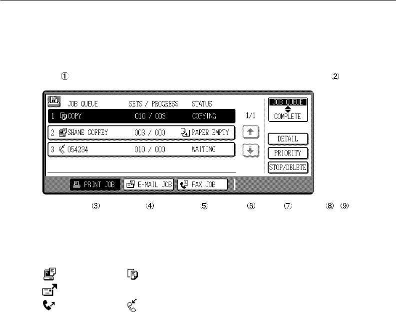
Job status screen (common to print, copy, network scan, and fax modes)
This screen is displayed when the [JOB STATUS] key on the operation panel is pressed.
A job list showing the current job at the top of the job queue or a list showing completed jobs can be displayed. The contents of the jobs can be viewed, moved up to the highest priority in the job queue or deleted from the queue.
|
|
|
|
|
|
|
|
|
|
|
|
|
|
|
|
|
|
|
|
|
|
|
|
|
|
|
|
|
|
|
|
|
|
|
|
|
|
JOB QUEUE |
|
|
|
SETS / PROGRESS |
|
STATUS |
|
|
|
|
|
|
|
|
|
JOB QUEUE |
|
|
|
||||||||||||||
|
|
|
|
|
|
|
|
|
|
|
|
|
|
|
|
|
|
|
|
|
|
||||||||||||||
|
|
|
|
|
|
|
|
|
|
|
|
|
|
|
|
|
|
|
|
|
|
|
|
|
|
|
|
|
|
|
|
|
|
|
|
|
|
COPY |
|
|
|
003 |
/ 000 |
|
|
|
COPYING |
|
|
|
|
|
1/1 |
|
|
COMPLETE |
|
|
|
||||||||||||
|
|
|
|
|
|
|
|
|
|
|
|
|
|
|
|
|
|
|
|
|
|||||||||||||||
|
|
|
|
|
|
|
|
|
|
|
|||||||||||||||||||||||||
|
|
|
|
|
|
|
|
|
|
|
|
|
|
|
|
|
|
|
|
|
|
|
|
|
|
|
|
|
|
|
|
|
|
||
|
|
|
|
|
|
|
|
|
|
|
|
|
|
|
|
|
|
|
|
|
|
|
|
|
|
|
|
|
|
|
|
|
|
|
|
|
|
SAGEM001 |
|
|
|
|
|
|
|
PAPER EMPTY* |
|
|
|
|
|
|
|
|
|
|
|
|
|
|
|
||||||||||
|
|
|
|
003 |
/ 000 |
|
|
|
|
|
|
|
|
|
|
|
|
|
|
|
|
|
|
||||||||||||
|
|
|
|
|
|
|
|
|
|
|
|
|
|
|
|
|
|
|
|
|
|
|
|
|
|
|
|
DETAIL |
|
|
|
|
|||
|
|
|
|
|
|
|
|
|
|
|
|
|
|
|
|
|
|
|
|
|
|
|
|
|
|
|
|
|
|
|
|||||
|
|
|
|
|
|
|
|
|
|
|
|
|
|
|
|
|
|
|
|
|
|
|
|
|
|
|
|
|
|
|
|
||||
|
|
|
|
|
|
|
|
|
|
|
|
|
|
|
|
|
|
|
|
|
|
|
|
|
|
|
|
|
|
|
|
|
|
|
|
|
|
054234 |
|
|
|
|
010 |
/ 000 |
|
|
|
WAITING |
|
|
|
|
|
|
|
|
|
|
|
|
|
|
|
|
|
||||||
|
|
|
|
|
|
|
|
|
|
|
|
|
|
|
PRIORITY |
|
|
|
|
|
|||||||||||||||
|
|
|
|
|
|
|
|
|
|
|
|
|
|
|
|
|
|
|
|
|
|
|
|
|
|
|
|
|
|
|
|
||||
|
|
|
|
|
|
|
|
|
|
|
|
|
|
|
|
|
|
|
|
|
|
|
|
|
|
|
|
|
|
|
|||||
|
|
|
|
|
|
|
|
|
|
|
|
|
|
|
|
|
|
|
|
|
|
|
|
|
|
|
|
|
|
|
|
|
|
|
|
|
|
|
|
|
|
|
|
|
|
|
|
|
|
|
|
|
|
|
|
|
|
|
|
|
|
|
|
|
|
|
|
|
|
|
|
|
|
|
|
|
|
|
|
|
|
|
|
|
|
|
|
|
|
|
|
|
|
|
|
|
|
|
|
STOP/DELETE |
|
|
|
||||
|
|
|
|
|
|
|
|
|
|
|
|
|
|
|
|
|
|
|
|
|
|
|
|
|
|
|
|
|
|
|
|
|
|
|
|
|
|
|
|
|
|
|
|
|
|
|
|
|
|
|
|
|
|
|
|
|
|
|
|
|
|
|
|
|
|
|
|
|
|
|
|
|
|
|
|
|
|
|
|
|
|
|
|
|
|
|
|
|
|
|
|
|
|
|
|
|
|
|
|
|
|
|
|
|
|
|
|
|
|
|
PRINT JOB |
|
|
|
|
E-MAIL/FTP |
|
|
FAX JOB |
|
|
|
|
|
|
|
|
|
|
|
|
|
|
|
|
||||||||
|
|
|
|
|
|
|
|
|
|
|
|
|
|
|
|
|
|
|
|
|
|
|
|
|
|
|
|
|
|
|
|
|
|
|
|
|
|
|
|
|
|
|
|
|
|
|
|
|
|
|
|
|
|
|
|
|
|
|
|
|
|
|
|
|
|
|
|
|
|
|
|
 Job list
A job list which indicates the current job and reserved jobs or a job list which indicates completed jobs is displayed. The icons to the left of the jobs in queue represent the job mode.
Print mode |
Copy mode |
Network scan mode |
|
Fax mode |
Fax mode |
(transmission job) |
(reception job) |
When a job list which indicates the current job and reserved jobs is displayed, the displayed jobs themselves are operation keys. To cancel printing or to give a job the highest print priority, touch the relevant job key to select the job and execute the desired operation using the keys described in  ,
,  , and
, and  .
.
*“PAPER EMPTY” in the job status display
When a job status display indicates “PAPER EMPTY”, the specified size paper is not loaded in any tray to run that job.
In this case, printing is suspended for that job until the required paper is loaded.
Until the required paper is loaded another reserved job data will be printed if possible.
(If paper runs out during printing, another job will not be printed.) If you wish to change the paper size because you do not have the specified size paper, you can change the size by touching the current job key to select it and touch the [DETAIL] key described in  .
.
1-14
 Mode switching key
Use to switch the job list between “JOB QUEUE” and “COMPLETE”.
“JOB QUEUE”: Displays the list of the current job and the reserved jobs.
“COMPLETE”: Displays the list of completed jobs.
 [PRINT JOB] key
Use to display the print job list for all modes (print, copy, network scan, and fax).
 [E-MAIL/FTP] key
Use to display the list of jobs that use the network for sending e-mail by SNMP protocol or sending to an ftp site or desktop by ftp protocol.
 [FAX JOB] key
Use to display the fax communication status and the reserved transmission job status.
 Display switching keys
Use to switch the page of the displayed job list.
 [STOP/DELETE] key
Use to cancel or delete the current job or delete the selected reserved job. Received fax print jobs that have been reserved, however, cannot be deleted.
 [PRIORITY] key
If you select a job among the reserved jobs in the “JOB QUEUE” job list to which you wish to give the highest priority and touch this key, the job will move to the highest priority reserved job.
 [DETAIL] key
Use to display the detailed information of the selected job. The paper size for printing can be changed from the specified size.This function, however, cannot be used when a fax reception print job is selected.

PART NAMES AND FUNCTIONS
Using the touch panel
■ How to use the touch panel
[Example 1]
JOB QUEUE |
SETS / PR |
||
COPY |
003 |
/ 00 |
|
SAGEM001 |
003 |
/ |
00 |
054234 |
010 |
/ |
00 |
Beep
tone
[Example 2]
1/13 COMPLETE
Items on the touch panel are easily selectable by touching the key associated with the item with a finger. Selection of an item will be accompanied with a beep tone to confirm the item was selected. Also, the key area for the item will be highlighted for visual confirmation.
Keys which are grayed out on any screen are not selectable. If a grayed out key is touched, a double beep will be sounded.
The confirmation beeps can be disabled by a key operator program. (See page 6-9.)
■ Selection of function
[Example 1]
|
010 / 000 |
WAITING |
OK |
1 |
|
|
|
||||
1. |
82 |
11 |
PLAIN |
|
|
|
1 |
|
|
|
|
2. |
82 |
11 |
TRANSPARENCY |
PAPER SELECT |
|
|
1 |
|
|
|
|
3. |
11 17 |
PLAIN |
|
|
|
Items which are highlighted at the time a screen appears are already selected and will be registered to function if the [OK] key is touched.
[Example 2]
DUAL PAGE
COPY
MULTI SHOT
When the machine is used in the copy or fax modes, the functions shown below can only be set on the special feature screen. They can be set or cancelled by alternate touches on the panel.
Copier feature |
Facsimile feature |
|
|
Dual page copy |
Polling |
Job build |
Dual page scan |
|
|
[Example 3]
READY TO SCAN FOR COPY.
SPECIAL MODES
2-SIDED COPY
OUTPUT
READY TO SEND.
AUTO
EXPOSURE
STANDARD
RESOLUTION
PROGRAMMED
FILE FORMAT
AUTO
ORIGINAL
When the machine is used in the copy or fax modes and a special feature is selected, a corresponding icon representing the feature will appear on the touch key and on the main screen of the mode selected. If this icon is touched, the setting screen of the function (or a menu screen) will appear, allowing the settings to be checked or adjusted and the function to be canceled easily.
1-15

LOADING PAPER
The message “ADD PAPER” or “OPEN TRAY 
 AND ADD PAPER” will appear when paper runs out during operation. Follow the procedure below to load paper.
NOTES
●Do not use curled or folded paper. Doing so may cause a misfeed.
●For best results use paper supplied by SAGEM. (See page 1-18.)
●When you change the paper type and size in paper tray 1, set the paper type and size referring to “Setting the paper size and type” (page 1-19).
●Do not place heavy objects or press hard on any tray which is pulled out.
Loading paper in paper tray 1
1 Pull out paper tray 1.
Gently pull the tray out until it stops.
2 Load paper into the tray.
Do not load paper above the maximum height line (approximately 500 sheets of 20 lbs. (80 g/m2) paper).
3 Gently push tray 1 into the machine.
Push the tray firmly all the way into the machine.
4 Set the paper type.
If you change the paper type, be sure to set the paper type referring to “Setting the paper size and type” (page 1-19).
5 Loading paper in paper tray 1 is now complete.
Changing the paper size in paper tray 1
For paper tray 1, 8-1/2" x 11", A4 or B5 size paper can be set. Use the following procedure to change the size as needed.
1 Pull out paper tray 1.
If paper remains in the tray, remove it.
2 Adjust the guide plates A and B in the tray to the length and width of the paper.
The guide plates A and B are slidable. Adjust them to the paper size to be loaded while squeezing their lock levers.
3 Load paper into the tray.
4 Gently push tray 1 into the machine.
Push the tray firmly all the way into the machine.
5 Set the paper size.
Be sure to set the paper size and paper type referring to “Setting the paper size and type” (page 1-19).
If this is not done, paper misfeeds will occur.
6 Changingcomplete. paper size in paper tray 1 is now
1-16

LOADING PAPER
Specifications of paper trays
The specifications for types and sizes of paper for loading paper trays are shown below.
1
Tray |
Tray No. |
Applicable paper types |
Applicable paper sizes |
Paper |
||||
(tray name) |
weight |
|||||||
|
|
|
|
|
|
|||
|
|
|
|
|
|
|
|
|
Paper tray 1 |
Tray 1 |
Plain paper |
(Refer to the next |
● 8-1/2 x 11, A4, B5 |
16 to 28 lbs. |
|||
|
|
|
page for applicable plain papers.) |
|
or 60 to 105 |
|||
|
|
|
|
|
|
|
g/m2 |
|
|
|
|
Plain paper (Refer to the next |
● If "AUTO-INCH" is selected in setting the |
|
|||
|
|
|
page for applicable plain papers.) |
paper size and type (page 1-19), the |
|
|||
|
|
|
|
|
|
following paper sizes can be used with the |
|
|
|
|
|
|
|
|
automatic detection function: |
16 to 34 lbs. |
|
|
|
|
|
|
|
11 x 17, 8-1/2 x 14, 8-1/2 x 11, 8-1/2 x 11R, |
||
|
|
|
|
|
|
or 60 to 128 |
||
|
|
|
|
|
|
7-1/4 x 10-1/2R, 5-1/2 x 8-1/2R |
g/m2 |
|
|
|
|
|
|
|
● If "AUTO-AB" is selected in setting the |
||
|
|
|
|
|
|
|
||
|
|
|
|
|
|
paper size and type (page 1-19), the |
|
|
|
|
|
|
|
|
following paper sizes can be used with the |
|
|
|
|
|
|
|
|
automatic detection function: |
|
|
|
|
|
|
|
|
A3, B4, A4, A4R, B5, B5R, A5R, 8-1/2 x 13 |
|
|
|
|
|
|
|
|
● Non-standard sizes |
|
|
|
Upper |
Tray 2 |
Special paper |
|
● Thick paper |
● If "AUTO-INCH" is selected in setting the |
See the |
|
|
|
|
(Refer to the |
|
● Labels, |
paper size and type (page 1-19), the |
remarks for |
|
|
|
|
next page for |
|
transparency |
following paper sizes can be used with the |
special paper |
|
|
|
|
applicable |
|
film |
automatic detection function: |
on the next |
|
|
|
|
special |
|
|
8-1/2 x 11, 8-1/2 x 11R |
page. |
|
|
|
|
papers.) |
|
|
● If "AUTO-AB" is selected in setting the |
|
|
|
|
|
|
|
|
|
||
|
|
|
|
|
|
paper size and type (page 1-19), the |
|
|
|
|
|
|
|
|
following paper sizes can be used with the |
|
|
|
|
|
|
|
|
automatic detection function: |
|
|
|
|
|
|
|
|
A4, A4R, B5, B5R |
|
|
|
|
|
|
|
|
● Non-standard sizes smaller than 8-1/2 x 11 |
|
|
Stand/3 x |
|
|
|
|
|
or A4 |
|
|
|
|
|
|
|
|
|
||
|
|
|
|
Postcard |
● Japanese official postcard |
|
||
500 sheet |
|
|
|
|
|
|||
paper |
|
|
|
|
Envelopes can |
● Applicable standard size envelopes: |
|
|
drawer |
|
|
|
|
|
|||
|
|
|
|
only be fed from |
COM-10, Monarch, DL, C5, ISO B5 |
|
||
|
|
|
|
|
|
|||
|
|
|
|
|
the multi-purpose |
● Non-standard size |
|
|
|
|
|
|
|
drawer. |
|
|
|
|
|
|
|
|
Applicable paper |
|
|
|
|
|
|
|
|
stock weight for |
|
|
|
|
|
|
|
|
envelopes is 20 |
|
|
|
|
|
|
|
|
to 23 lbs. or 75 to |
|
|
|
|
|
|
|
|
90 g/m2. |
|
|
|
|
|
|
|
|
|
|
|
|
|
Middle |
Tray 3 |
Plain paper |
(Refer to the next |
● If "AUTO-INCH" is selected in setting the |
16 to 28 lbs. |
||
|
||||||||
|
|
|
page for applicable plain papers.) |
paper size and type (page 1-19), the |
or 60 to 105 |
|||
|
|
|
|
|
|
following paper sizes can be used with the |
g/m2 |
|
|
|
|
|
|
|
automatic detection function: |
|
|
|
|
|
|
|
|
11 x 17, 8-1/2 x 14, 8-1/2 x 11, 8-1/2 x 11R, |
|
|
|
|
|
|
|
|
7-1/4 x 10-1/2R |
|
|
|
Lower |
Tray 4 |
|
|
|
● If "AUTO-AB" is selected in setting the |
|
|
|
|
|
|
|
|
paper size and type (page 1-19), the |
|
|
|
|
|
|
|
|
following paper sizes can be used with the |
|
|
|
|
|
|
|
|
automatic detection function: |
|
|
|
|
|
|
|
|
A3, B4, A4, A4R, B5, B5R, 8-1/2 x 13 |
|
|
|
|
|
|
|
|
|
||
Stand/ |
Upper |
Tray 2 |
See upper tray |
|
|
|||
MPD & |
|
|
|
|
|
|
|
|
Lower |
Tray 3 |
Plain paper |
(Refer to the next |
● 8-1/2 x 11, A4 |
16 to 28 lbs. |
|||
2000 |
||||||||
|
|
page for applicable plain papers.) |
|
or 60 to 105 |
||||
sheet |
|
|
|
|||||
|
|
|
|
|
|
g/m2 |
||
paper |
|
|
|
|
|
|
||
|
|
|
|
|
|
|
||
drawer |
|
|
|
|
|
|
|
|
|
|
|
|
|
|
|
|
|
1-17

LOADING PAPER
■ Applicable plain paper
For satisfactory results, plain paper must conform to the following requirements.
|
Paper in AB system |
Paper in inch system |
|
|
|
|
A5 to A3 |
5-1/2 x 8-1/2 to 11 x 17 |
|
|
|
Plain paper |
16 to 28 lbs. or 60 to 105 g/m2 |
|
Recycled, colored, pre-punched, pre-printed and letterhead papers must conform to the same conditions as above.
■ Applicable special paper
For satisfactory results, special paper must conform to the following requirements.
|
Type |
Remarks |
|
|
|
Special paper |
Thick paper |
● For 5-1/2 x 8-1/2 to 8-1/2 x 11 or A5 to A4 sizes, thick |
|
|
paper ranging from 16 to 34 lbs. or 60 to 128 g/m2 can be |
|
|
used. |
|
|
● For sizes larger than 8-1/2 x 11 or A4, thick paper ranging |
|
|
from 16 to 28 lbs. or 60 to 105 g/m2 can be used. |
|
|
● Other thick papers |
|
|
Index stock (65 lbs. or 176 g/m2) can be used. |
|
|
Cover stock (110 lbs. or 200 to 205 g/m2) can be used but |
|
|
only for 8-1/2 x 11, A4 paper in the portrait orientation. |
|
|
● For 5-1/2 x 8-1/2 or A5 paper, the orientation must be |
|
|
landscape. |
|
Transparency film, labels, |
● Use SAGEM recommended paper. Do not use labels other |
|
and tracing paper |
than SAGEM recommended labels. Doing so may leave |
|
|
adhesive residue in the printer, causing paper misfeeds, |
|
|
smudges on prints or other machine trouble. |
|
Postcards |
● Japanese official postcards can be used. |
|
Envelopes |
● Applicable standard envelopes: COM-10, Monarch, DL, C5, |
|
|
ISO B5 |
|
|
● Envelopes can only be fed from the multi-purpose drawer. |
|
|
Applicable paper stock weight for envelopes is 20 to 23 |
|
|
lbs. or 75 to 90 g/m2. |
1-18

LOADING PAPER
Setting the paper size and type
For the specifications for types and sizes of paper for loading paper trays, see page 1-17.
Setting the paper size and type from the operation panel on the main printer
When the paper size or type is changed in a paper tray, set them referring to the following procedure.
1 |
Press the [MENU] key repeatedly until |
7 |
Press the [OK] key. |
1 |
“CUSTOM SETTINGS” appears in the |
To cancel the setting change, press the [BACK/C] |
|||
|
message display. |
|
key to return to step 4. |
|
8 Select the paper type that has been set in the tray.
2 Press the [OK] key.
3 Press the [OK] key.
TRAY SETTING
TRAY1
When the [OK] key is pressed,“TRAYSETTING” will appear in the message display.
When the [OK] key is pressed,the message shown to the left will appear in the message display.
|
Press the |
or |
key |
|
PLAIN |
||||
repeatedly until the paper |
||||
OK? |
||||
type that has been set |
||||
|
||||
|
appears. |
|
|
|
NOTE
Special paper such as thick paper, transparency film, labels, and postcards can be set for tray 2 and the bypass tray.
Envelopes can be set only for tray 2.
9 Press the [OK] key.
10Ensure that the desired paper size is selected.
|
Press the |
key or |
key |
|
LETTER |
||||
repeatedly until |
the |
|||
OK? |
||||
desired |
paper |
size |
||
|
||||
appears.
4
5
Select the desired paper tray.
Press the  or
or  key repeatedly until the desired paper tray is indicated in the display.
Press the [OK] key.
The paper size and paper type of the tray selected in step 4 will appear.
●Depending on the selected tray, a selection for “AUTO-AB” and “AUTO-INCH” may appear. “AUTO-AB”: Select when you have setAB system paper.
“AUTO-INCH”: Select when you have set inch system paper.
When the paper system is changed from the inch system to the AB system or vise versa, the paper type must be designated. Select the paper type.
●If you have set paper of non-standard size, select “NON STANDARD”. This size can be selected when tray 2 or the bypass tray has been selected in step 4.
LETTER
PLAIN
6 Press the  key.
key.
CHANGE TRAY1
SETTING OK?
If TRAY 1 is selected in
step 4, the message 11Press the [OK] key to complete the setting. shown to the left will
appear in the display.
If TRAY 1 is selected in step 4, the message shown to the left will appear in the display.
1-19
LOADING PAPER
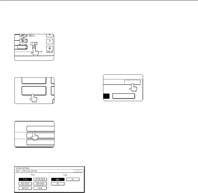
Setting the paper type and size from the touch panel
1 Press the [CUSTOM SETTINGS] key.
The custom setting menu screen will appear.
“AUTO-INCH”: Select when you have set inch system paper.
When the paper system is changed from the inch system to the AB system or vise versa, the paper type must be designated. Select the paper type.
●If you have set paper of non-standard size, select “NON STANDARD SIZE”. This size key appears when tray 2 or the bypass tray has been selected in step 3.
2 Press the [TRAY SETTINGS] key.
5 Touch the [OK] key to complete the setting.
TOTAL COUNT
TRAY SETTINGS
The paper tray selection |
OK |
screen will appear. |
|
|
SIZE |
|
A4 |
3 Select the paper tray for which the setting is to be made.
|
TYPE / SIZE |
TRAY1 |
PLAIN / 81/2X11 |
TRAY2 |
PLAIN / AUTO-INCH |
TRAY3 |
RECYCLED / AUTO-INCH |
If the desired tray is not on the display, use [  ] or [
  ] key to scroll the display until it appears.
4 Select the paper type and the paper size.
● If TRAY 1 has been selected in step 3:
CUSTOM SETTINGS |
|
|
|
|
|
|
|
|
|
|
|
|
|
|
||||
|
|
|
|
|
|
|
|
|
|
|
|
|
|
|
|
|
|
OK |
TRAY 1 TYPE/SIZE SETTING |
|
|
|
|
|
|
|
|
|
|||||||||
|
|
|
|
|
|
|
|
|
|
|
|
|
|
|
||||
|
|
|
|
|
|
|
|
|
|
|
|
|
|
|
|
|
|
|
|
|
|
|
|
TYPE |
|
|
|
|
|
|
|
|
SIZE |
|
|||
|
|
|
|
|
|
|
|
|
|
|
|
|
|
|||||
|
|
PLAIN |
|
|
LETTER HEAD |
|
|
8 |
2 |
11 |
|
|
A4 |
|||||
|
|
|
|
|
|
|
|
|
|
1 |
|
|
|
|
|
|
||
|
|
|
|
|
|
|
|
|
|
|
|
|
|
|
|
|
|
|
|
|
|
|
|
|
|
|
|
|
|
|
|
|
|
|
|
|
|
|
PRE-PRINTED |
|
PRE-PUNCHED |
|
|
|
|
B5 |
|
|
|
|
||||||
|
|
|
|
|
|
|
|
|
|
|
|
|
|
|
|
|
||
|
RECYCLED |
|
COLOR |
|
|
|
|
|
|
|
|
|
|
|
||||
The highlighted keys indicate the current selections. To change either type or size or both, touch the desired keys to highlight the selections.
Paper types
Special papers such as transparency film and labels can be set for tray 2 and the bypass tray. Envelopes can be set only for tray 2.
Paper sizes
●Depending on the selected tray, a selection for “AUTO-AB” and “AUTO-INCH” may appear. “AUTO-AB”: Select when you have setAB system paper.
1-20

LOADING PAPER
Loading paper in the stand/3 x 500 sheet paper drawer
Upper paper tray:
The upper tray is the same as the multi-purpose drawer. Use the upper tray according to the instructions for the multipurpose drawer on page 1-16.
Middle and lower paper trays: |
1 |
|
Up to 500 sheets of SAGEM recommended plain paper can be loaded in these trays. The method of loading paper is the |
||
same as for paper tray 1 in the main unit. See the description (page 1-16). |
||
|
|
|
NOTE |
|
|
If the paper size or paper type is changed in either paper tray, the tray settings must be changed in custom settings. Refer |
|
|
to “Setting the paper size and type” on page 1-19. |
|
|
|
|
|
Specifications (stand/3 x 500 sheet paper drawer)
Name |
Stand/3 x 500 sheet paper drawer |
Paper size/weight |
See specifications of paper trays on page 1-17. |
Paper capacity |
500 sheets (20 lbs. (80 g/m2)) each |
(ordinary paper) |
|
Dimensions |
24-3/8" (W) x 26-5/32" (D) x 15-29/32" (H) |
|
(619 mm (W) x 664 mm (D) x 404 mm (H)) |
Weight |
Approximately 70.6 lbs. or 32 kg |
Specifications are subject to change for improvement without notice.
Loading paper in the stand/MPD & 2000 sheet paper drawer
Upper paper tray:
The upper paper tray is equivalent to the multi purpose drawer. The method of loading paper and the paper that can be used are the same as for the multi purpose drawer. Refer to the description of the multi purpose drawer (see page 1-16).
Lower paper tray:
The lower paper tray is a large capacity tray that holds 2,000 sheets of 8-1/2" x 11" or A4 paper (20 lbs. (80 g/m2)). Use the following procedure to load paper in the large capacity tray.
NOTE
If the paper size or paper type is changed in either paper tray, the tray settings must be changed in custom settings. Refer to “Setting the paper size and type” on page 1-19.
1-21
 Loading...