


 Loading...
Owner’s Manual
Owner’s Manual (this document)
Read this first. It explains the basic things you need to know in order to use the MC-101.
PDF Manual (download from the Web)
55 Reference Manual
This explains all parameters of the MC-101.
To obtain the PDF manual
1. Enter the following URL in your computer. |
2. Choose “MC-101” as the product name. |
http://www.roland.com/manuals/
Before using this unit, carefully read “USING THE UNIT SAFELY” (p. 20) and “IMPORTANT NOTES” (p. 23). After reading, keep the document(s) where it will be available for immediate reference.
© 2019 Roland Corporation

Panel Descriptions
Top Panel
1 |
2 |
6 |
3 4
5
1Common Section 1 [VOLUME] knob
Adjusts the volume of the OUT jacks.
[SHIFT] button
When you hold down the [SHIFT] button and press a button that’s labeled with a function name (such as  ), that function is executed.
[PROJECT] button
Accesses the project menu screen.
Here you can load a project and make settings for it.
When used together with the [SHIFT] button, this functions as the [CLEAR] button.
By using the [CLEAR] button together with other buttons, you can clear the recorded contents of the step sequencer or the contents of a phrase.
TRACK SEL [1]–[4] button
Select tracks.
If you hold down the [SHIFT] button and press the [SEL] button, the track settings menu appears.
&For details, refer to “Reference Manual” (PDF).
MEASURE [<] [>] buttons
Move to the measure that you want to edit.
If you hold down the [SHIFT] button and press a MEASURE [<][>] button, the measure length edit screen appears.
&For details, refer to “Reference Manual” (PDF).
Measure display indicators
The four indicators show the measure that you’re editing.
2

|
|
Panel Descriptions |
|
|
|
|
|
|
[p] (play/stop) button |
4 Control Section |
|
|
Starts or stops playback. |
[C1]–[C4] knobs |
|
|
|
||
|
[t] (rec) button |
Necessary functions are assigned to these knobs de- |
|
|
Turns on/off recording of your performance using the |
pending on the operation. |
|
|
|
||
|
pads. |
[SOUND] button |
|
|
If you hold down the [SHIFT] button and press the [t] |
||
|
Assigns the [C1]–[C4] knobs to control the SOUND |
||
|
(record) button, QUANTIZE turns on. |
||
|
&For details, refer to “Reference Manual” (PDF). |
parameter of track 1–4. |
|
|
If you hold down the [SHIFT] button and press the |
||
2 |
|
||
Master Effect Section |
[SOUND] button, the sound edit screen appears. |
||
|
[MULTI FX] button |
&For details, refer to “Reference Manual” (PDF). |
|
|
|
||
|
Turns the selected effect on/off. |
[FILTER] button |
|
|
|
||
|
If you hold down the [SHIFT] button and press the |
Assigns the [C1]–[C4] knobs to control the FILTER param- |
|
|
[MULTI FX] button, the MULTI FX edit screen appears. |
eter of track 1–4. |
|
|
&For details, refer to “Reference Manual” (PDF). |
If you hold down the [SHIFT] button and press the |
|
|
[FX PRM] [FX DEPTH] knob |
[FILTER] button, the UTILITY screen appears. |
|
|
[MOD] button |
||
|
Adjust the effect depth. |
||
|
Assigns the [C1]–[C4] knobs to control the MOD param- |
||
3 |
Mixer Section |
||
eter of track 1–4. |
Level faders |
If you hold down the [SHIFT] button and press the [MOD] |
|
button, the MOTION screen appears. |
||
|
||
Adjusts the volume. |
|
3

Panel Descriptions
[FX] button
Assigns the [C1]–[C4] knobs to control the FX parameter of track 1–4.
If you hold down the [SHIFT] button and press the [FX] button, the COPY screen appears.
5Pad Section Pads (16 pads)
The operation of the pads depends on the pad mode that’s selected.
Common Section 2 Display
Shows necessary information for various operations.
[VALUE] dial
Turn: Edits a value or scrolls the screen. The operation depends on what is shown in the screen.
Press: Confirms the editing value or executes the operation.
[EXIT] button
Returns to the previous screen.
In some screens, cancels the currently-executing function.
If you hold down the [SHIFT] button and press the [EXIT] button, the TAP screen appears.
[TEMPO] button
If the [TEMPO] button is lit, you can use the display and the [VALUE] dial to change the TEMPO setting.
If you hold down the [SHIFT] button and press the [TEMPO] button, the WRITE screen appears.
PAD [CLIP] button
Switches the pads to CLIP mode. In CLIP mode, you can use the TRACK SEL [1]–[4] buttons to switch clips in the selected track.
If you hold down the [SHIFT] button and press the [CLIP] button, you can then make settings related to CLIP mode.
4
Panel Descriptions
PAD [SEQ] button
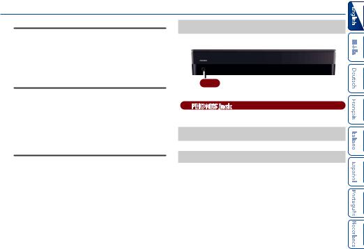
Front Panel
Switches the pads to SEQ mode (p. 15). In SEQ mode, you can use the lit pads to step-record a melody or steprecord drums.
If you hold down the [SHIFT] button and press the [SEQ] button, you can then make settings related to SEQ mode.
PAD [NOTE] button
Switches the pads to NOTE mode (p. 14). In NOTE mode, you can use the lit pads to play a melody or drums.
If you hold down the [SHIFT] button and press the [NOTE] button, you can then make settings related to NOTE mode.
PAD [SCATTER] button
Switches the pads to SCATTER mode. In SCATTER mode, you can use the lit pads to apply the SCATTER effect.
If you hold down the [SHIFT] button and press the [SCATTER] button, you can then make settings related to SCATTER mode.
A
APHONES jack
You can connect a set of headphones here.
Bottom Panel
Installing the Batteries
As an alternative to USB bus power, you can use commercially available
AAnickel-metal hydride batteries or alkaline batteries to power the unit.
*If USB bus power is being supplied, the unit uses USB bus power even if batteries are installed.
1. Remove the battery cover.
*When turning the unit over, be careful so as to protect the buttons and knobs from damage. Also, handle the unit carefully; do not drop it.
5

Panel Descriptions
2.Taking care to observe the correct orientation of the batteries, insert the batteries into the battery case.
Rear Panel (Connecting Your Equipment)
*To prevent malfunction and equipment failure, always turn down the volume, and turn off all the units before making any connections.
B [POWER] switch |
&“Turning the MC-101 On” |
(p. 7) |
D |
E |
MIDI port |
|
Connect MIDI devices. |
3. Close the battery cover.
*If you handle batteries improperly, you risk explosion and fluid leakage. Make sure that you carefully observe all of the items related to batteries that are listed in “USING THE UNIT SAFELY” (p. 20) and “IMPORTANT NOTES” (p. 23).
Battery replacement indicator
When the batteries run low, an indication appears in the screen.
When this occurs, install new batteries.
SD card
C O(USB) port |
Computer |
F OUT jack |
6

Panel Descriptions
B [POWER]
 switch
Turns the power on/off.
C O(USB) port
Use a commercially available USB 2.0 cable (type B) to connect this port to your computer. It can be used to transfer USB MIDI and USB audio data. You must install the USB driver when connecting this unit to your computer. For details, refer to Readme.htm in the downloaded file.
&https://www.roland.com/support/
*If USB bus power is being supplied, the unit operates on USB bus power.
DSD card slot
With the factory settings, the SD card protector is fastened with the included SD card inserted. If you want to take out the SD card, remove the screws.
The SD card contains various data (settings, sounds, samples, etc.) for this unit.
*Never turn off the power or remove the SD card while the SD card is being accessed.
*Some memory card types or memory cards from some manufacturers may not record or play back properly on the unit.
EMIDI port
Connect these to external MIDI equipment to transmit and receive MIDI messages.
FOUT L/MONO, R jacks
These are audio output jacks. Connect them to your amp or monitor speakers.
If you’re outputting in mono, connect the L/MONO jack.
Turning the MC-101 On
1.Power-on your equipment in the order of MC-101 0connected equipment.
2.Power-on the connected equipment, and raise the volume to an appropriate level.
Turning Off the Power
1.Power-off your equipment in the order of connected equipment 0MC-101.
7

An Overview of the MC-101
MC-101 |
|
System Setting |
|
|
|
|
|
|
|
|
|
|
|
Project |
|
Project Setting |
|
User Sample |
|
|
|
|
|
|
|
||
|
|
|
Track Mix |
Multi Effect |
Master |
Equalizer |
|
Track 1–4 |
|
|
Compressor |
||
|
|
|
|
|
||
|
|
|
|
Reverb |
|
|
Tone/ |
|
|
Track 1–4 |
MASTER FX Setting |
||
Drum Kit/ |
MFX |
EQ |
|
|
|
|
Looper |
|
|
|
Chorus/ |
|
|
|
|
|
|
Delay |
|
|
Track 1–4
Types of track and their internal structure |
|
|
|
|
||
Type: Tone |
Type: Drum |
Type: Looper |
Type: None |
|
|
|
Tone |
Drum Kit |
Looper |
None |
Preset |
|
Save |
|
|
|||||
MFX |
MFX |
MFX |
|
|
|
Load |
Clip 1 |
Clip 1 |
Clip 1 |
|
|
|
|
|
|
|
|
Browser |
Card |
|
|
|
|
|
(Load) |
|
|
Clip 16 |
Clip 16 |
Clip 16 |
|
|
Audio Data |
Project Data |
|
|
|
|
|
||
8
Loading...