


KTN-50
Table of contents
 Loading...
Oct. 2016 KTN-50
SERVICE NOTES
Issued by RJA
KATANA-50
Table of Contents
Cautionary Notes ..............................................................2
Specifications .....................................................................3
Location of Controls (Top)...............................................4
Location of Controls Parts List (Top) .............................4
Location of Controls (Rear)..............................................5
Location of Controls Parts List (Rear)............................5
Exploded View (Cabinet).................................................6
Exploded View Parts List (Cabinet) ...............................7
Disassembly Procedure....................................................7
Plain View (Cabinet: 1).....................................................8
Plain View (Cabinet: 2).....................................................9
Exploded View (Chassis) ...............................................10
Exploded View Parts List (Chassis)..............................11
Plain View (Chassis: 1) ...................................................12
Plain View (Chassis: 2) ...................................................13
Wiring Diagram/Block Diagram..................................14
Parts List ...........................................................................16
Verifying the Version......................................................19
Data Backup and Restore Operations ..........................19
System Update Procedure..............................................19
Performing a Factory Reset............................................19
Test Mode.........................................................................20
Circuit Board (Main Board) ...........................................24
Circuit Diagram (Main Board: 1/3)..............................26
Circuit Diagram (Main Board: 2/3)..............................28
Circuit Diagram (Main Board: 3/3)..............................30
Circuit Board (Panel, Amp, Jack, Input, Fuse Board) 32
Circuit Diagram (Panel Board)......................................34
Circuit Diagram (Amp Board).......................................36
Circuit Diagram (Jack Board) ........................................37
Circuit Diagram (Input Board)......................................38
Circuit Diagram (Fuse Board) .......................................38
Copyright © 2016 Roland Corporation
All rights reserved. No part of this publication may be reproduced in any form without the written permission
of Roland Corporation.
CC-KWS17057053E0

Oct. 2016 KTN-50
Cautionary Notes
Before beginning the procedure, please read
through this document. The matters described may
differ according to the model.
Back Up User Data!
User data may be lost during the course of the procedure. Refer to Data
Backup and Restore Operations (p. 19) in the Service Notes and save the
data. After completing the procedure, restore the backed-up data to the
product.
Part Replacement
When replacing components near the power-supply circuit or a heatgenerating circuit (such as a circuit provided with a heat sink or including a
cement resistor), carry out the procedure according to the instructions with
respect to the part number, direction, and attachment position (mounting so as
to leave an air gap between the component and the circuit board, etc.).
Parts List
A component whose part code is ******** will not be supplied as a service part
because one of the following reasons applies.
• Because it is supplied as an assembled part (under a different part code).
• Because a number of circuit boards are grouped together and supplied as
a single circuit board (under a different part code).
• Because supply is prohibited due to copyright restrictions.
• Because reissuance is restricted.
• Because the part is made to order (at current market price).
• Because it is carried in electronic data on the Roland web site.
• Because it is a package or an accessory irrelevant to the function
maintenance of the main body.
• Because it can be replaced with an article on the market. (battery or etc.)
Circuit Diagram
In the circuit diagram, “NIU” is an abbreviation for “Not in Use,” and
“UnPop” is an abbreviation for “Unpopulated.” They both mean non-mounted
components. The circuit board and circuit board diagram show silk-screened
indications, but no components are mounted.
Roland Japan Warranty
Please send the problem report with followings when the defect occurred
within one year from production and within one month from the first
customer’s purchase.
• Model name:
• Serial number:
•Version:
• Purchase date by the first customer: yyyy/mm/dd
•Symptom:
• Frequency: always, sometimes or seldom
• Confirmed the symptom at your service dept: Yes/No
Please send the problem report to rjasc@roland.co.jp.
2

Oct. 2016 KTN-50
Specifications
BOSS KATANA-50: Guitar Amplifier
Rated Power Output
50 W
Nominal Input Level
INPUT: -10 dBu (1 MΩ)
AUX IN: -10 dBu
Speaker
30 cm (12 inches) x 1
Controls
POWER switch
MASTER knob
POWER CONTROL switch (STANDBY, 0.5 W, 25 W, 50 W)
[AMPLIFIER]
AMP TYPE switch (ACOUSTIC, CLEAN, CRUNCH, LEAD, BROWN)
GAIN knob
VOLUME knob
[EQUALIZER]
BASS knob
MIDDLE knob
TREBLE knob
[MULTI EFFECT]
BOOSTER/MOD button
DELAY/FX button
REVERB button
TAP button
BOOSTER/MOD knob
DELAY/FX knob
REVERB knob
[TONE SETTING]
CH1 button
CH2 button
PANEL button
Power Consumption
47 W
Dimensions
470 (W) x 238 (D) x 398 (H) mm
18-9/16 (W) x 9-3/8 (D) x 15-11/16 (H) inches
Weight
11.6 kg
25 lbs 10 oz
Accessories
Owner’s Manual (#5100052281)
Power cord (#5100029165, #5100012292, #00894378, #03450323, #5100013648,
#00907001, #00894389, #5100013842)
Options (sold separately)
Footswitch: BOSS FS-5L
Expression pedal: Roland EV-5, BOSS FV-500L, BOSS FV-500H
* 0 dBu = 0.775 Vrms
* Printed matters will not be supplied after the end of the production. Then,
download the electronic file from the Roland web site.
* In the interest of product improvement, the specifications and/or appearance of
this unit are subject to change without prior notice.
Indicators
BOOSTER/MOD
DELAY/FX
REVERB
TAP
CH1
CH2
PANEL
Connectors
INPUT jack: 1/4-inch phone type
AUX IN jack: Stereo miniature phone type
REC OUT/PHONES jack: Stereo 1/4-inch phone type
EXP PEDAL/CTL CH1/CH2 jack: 1/4-inch TRS phone type
USB port: USB B type
AC IN jack
3

Oct. 2016 KTN-50
Location of Controls (Top)
fig.panel-top.eps
5
1 2
3 87 94 6
Location of Controls Parts List (Top)
No. Part Code Part Name Description Q’ty
1 5100052218 S-KEYTOP 3
01780101 TACT SWITCH SKQKABD010 3
05011067 LED L-3WEGW (153-L-3WEGW) 3
2 5100052218 S-KEYTOP 3
01780101 TACT SWITCH SKQKABD010 3
5100003359 LED(RED) L-34ID (153-L-34IDSLLF) 3
5100051747 LED SPACER LH-5-1.5 3
3 5100031944 6.5MM JACK PJ-644C-EP 1
5100046593 JACK SPACER 1
******** JACK NUT attached to JACK 1
******** JACK WASHER attached to JACK 1
4 5100052214 R-KNOB INDEX 1
5100052460 ROTARY POTENTIOMETER RD901F-40-15F-B10K-05D60A 1
******** VR NUT (M9) attached to VR 1
5 5100052214 R-KNOB INDEX 8
5100052467 ROTARY POTENTIOMETER RD901F-40E1-15F-0B10K-00D86A 8
******** VR NUT (M9) attached to VR 8
6 5100052217 C-KEYTOP 1
01780101 TACT SWITCH SKQKABD010 1
5100003359 LED(RED) L-34ID (153-L-34IDSLLF) 1
5100051747 LED SPACER LH-5-1.5 1
7 5100052214 R-KNOB INDEX 1
5100022034 ROTARY POT(231-11017-03-00) RD901F-40E1-15F-1B20K-00DN6 1
******** VR NUT (M9) attached to VR 1
8 5100049813 INDEX KNOB 1
5100052466 ROTARY POTENTIOMETER RD901F-40-125F-B10K-04D60A 1
******** VR NUT (M7) attached to VR 1
9 02897801 SEESAW SWITCH SDDJE13200 94V-0 1
5100046595 POWER SW ESCUTCHEON 1
5100046598 POWER SW CUSHION 2
4
Oct. 2016 KTN-50
1 2 3 4 5
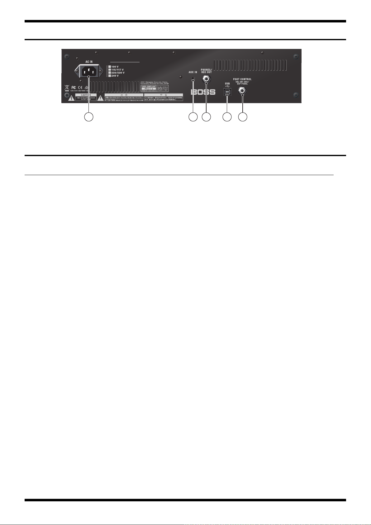
Location of Controls (Rear)
fig.panel-rear.eps
Location of Controls Parts List (Rear)
No. Part Code Part Name Description Q’ty
1 5100051443 AC INLET M1909-C 1
2 5100050453 3.5MM JACK HSJ2000-01-010 1
3 5100024419 6.5MM JACK PJ-644C-04-EP(610-11020-01-00 1
5100046593 JACK SPACER 1
******** JACK NUT attached to JACK 1
******** JACK WASHER attached to JACK attached to JACK 1
4 5100009531 USB CONNECTOR B TYPE FEMALE YKF45-0044N 1
5 5100031944 6.5MM JACK PJ-644C-EP 1
5100046593 JACK SPACER 1
******** JACK NUT attached to JACK 1
******** JACK WASHER attached to JACK attached to JACK 1
5
Oct. 2016 KTN-50
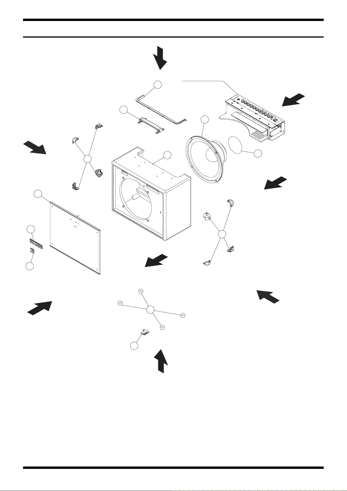
Exploded View (Cabinet)
fig.bunkai-cabinet.eps
View 3
Refer to Chassis
1
View 1
2
3
View 6
7
8
5
View 7
6
4
6
View 8
9
11
View 2
View 5
6
10
View 4

Oct. 2016 KTN-50
Exploded View Parts List (Cabinet)
No. Part Code Part Name Description Q’ty
1 5100052235 TRIM SASH 1
2 5100049817 HANDLE 1
3 5100052293 SPEAKER W1204-067A 1
5100053344 CABINET ASSY W/O SPEAKER 1
4 ******** CABINET 1
5 ******** NET BOARD 1
6 5100052238 CORNER PROTECTOR 8
7 5100052237 BOSS BADGE 1
8 5100053891 KATANA BADGE 1
9 5100041039 FOOT EK1206 4
10 5100052242 STAND FOOT 2
11 5100052278 LABEL SPEAKER MAGNET 1
* This unit includes the following parts.
Disassembly Procedure
Detaching the Chassis Assy
1. Detach the speaker wiring from the speaker.
2. Remove screws c (x 2) in View 3 (Plain View (Cabinet: 1) (p. 8)).
3. Remove screws a (x 4) in View 1 (Plain View (Cabinet: 1) (p. 8)).
4. Pull out the Chassis Assy.
* The speaker can be taken out at this status.
Detaching the Circuit Boards
1. Detach the Chassis Assy. (as described above)
2. Remove screws o (x 7) in View 6 (Plain View (Cabinet: 1) (p. 8)).
3. Detach the Chassis Cover Board and remove the connector (x 1).
4. When detaching the circuit boards, remove screws from the outside of the Chassis.
Detaching the Net Board
1. Detach the Chassis Assy. (as described above)
2. Remove the screws and washers k (x 4) in View 7 (Plain View (Cabinet: 2) (p. 9)).
3. Remove the nuts and washers y (x 2) in View 2 (Plain View (Cabinet: 1) (p. 8))
4. Push the Net Board to the front side.
7
Oct. 2016 KTN-50
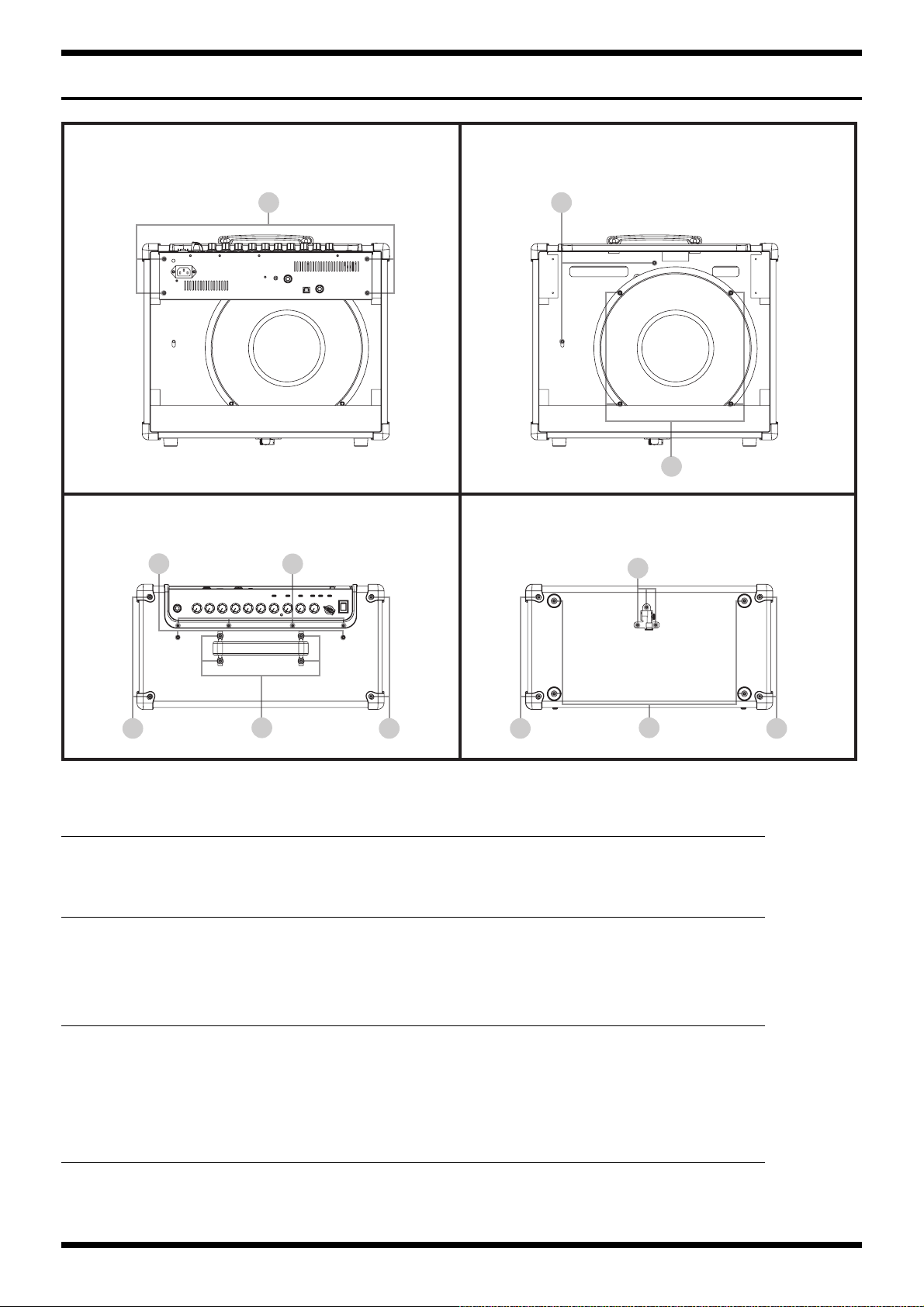
Plain View (Cabinet: 1)
fig.heimenzu-cabinet-1.eps
View 1 View 2
a y
p
View 3 View 4
c
d d d d
View 1
No. Part Code Part Name Description Q’ty
a 40010689 SCREW 4X25 TRUSS TAPPING A FE BZC 4
View 2
No. Part Code Part Name Description Q’ty
p 40010390 SCREW M5X25 BINDING HEAD FE BZC 4
y 5100053056 NUT M4 W/SW BZC 2
5100053055 PLAIN WASHER 4.2X14X1.0 BZC 2
b
e
f
g
View 3
No. Part Code Part Name Description Q’ty
b 5100053052 SCREW 3X14 TRUSS TAPPING A BZC 4
c 5100041078 ROSETTE WASHER M4 NI (MC-15042-20303-000) 2
5100047173 SCREW M4X25 OVAL MACHINE NI 2
d 5100043887 SCREW 3.5X16 TRUSS TAPPING A NI 4
e 5100048333 SCREW M4X15 OVAL MACHINE NI 4
View 4
No. Part Code Part Name Description Q’ty
d 5100043887 SCREW 3.5X16 TRUSS TAPPING A NI 4
f 40012145 SCREW 4X14 TRUSS TAPPING A FE BZC 3
g 5100024107 SCREW 4X16 BINDING TAPPING A FE BZC 4
8

Oct. 2016 KTN-50
Plain View (Cabinet: 2)
fig.heimenzu-cabinet-2.eps
View 5 View 6
d d
View 7 View 8
t
k
View 5, 6
No. Part Code Part Name Description Q’ty
d 5100043887 SCREW 3.5X16 TRUSS TAPPING A NI 8
View 7
No. Part Code Part Name Description Q’ty
k 5100033930 SCREW 4X25 TRUSS TAPPING A NI 4
5100053053 PLAIN WASHER 4.2X14X1.0 NI 4
View 8
No. Part Code Part Name Description Q’ty
t 40011323 SCREW 3X10 BINDING TAPTITE P BZC 3
40457245 PLAIN WASHER 3X12X1 ZC 3
9

Oct. 2016 KTN-50
Exploded View (Chassis)
fig.bunkai-chassis.eps
View 1
1
28
27
c
d
b
a
2
4
5
6
View 2
24
View 5
23
18
19
View 7
22
16
15
13
21
13
11
20
10
View 6
9
d
25
14
View 8
17
View 3
27
c
26
8
29
e
30
f
10
View 4

Oct. 2016 KTN-50
Exploded View Parts List (Chassis)
No. Part Code Part Name Description Q’ty
1 5100052214 R-KNOB INDEX 10
2 5100049813 INDEX KNOB 1
4 02897801 SEESAW SWITCH SDDJE13200 94V-0 1
5 5100046595 POWER SW ESCUTCHEON 1
6 5100046598 POWER SW CUSHION 2
8 5100051443 AC INLET M1909-C 1
9 5100052208 CHASSIS 1
10 5100052218 S-KEYTOP 6
11 5100052217 C-KEYTOP 1
13 5100046593 JACK SPACER 3
5100051560 PANEL SHEET ASSY 1
14 ******** PANEL BOARD 1
15 ******** INPUT BOARD 1
16 ******** JACK BOARD 1
17 ******** FUSE BOARD 1
18 ******** AMP BOARD 1
19 5100051571 MAIN BOARD ASSY 1
20 5100051957 POWER TRANSFORMER 100/117V for low voltage 1
21 5100052247 TRANS SHEET 1
22 5100052219 CHASSIS COVER BOARD 1
23 5100052288 POWER IC SHEET 1
24 5100052223 HEATSINK 1
25 5100049090 CU-CR-F 16X9X0.5 1
26 5100053011 EVA PACKING 155X10X0.5 W/ADH 1
27 5100052229 TOP CUSHION S 2
28 5100052228 TOP CUSHION L 1
29 40013812 CAUTION SEAL IEC #142
30 12199584 GROUNDING TERMINAL M1698 1
* This unit includes the following parts.
5100051960 POWER TRANSFORMER 225/240V for high voltage 1
a ******** VR NUT (M7) attached to VR 1
b ******** VR NUT (M9) attached to VR 10
c ******** JACK NUT attached to JACK 3
d ******** JACK WASHER attached to JACK 3
e 5100050484 HEX NUT M4 W/SPW ZC 1
f 40011889 EXTERNAL TOOTH WASHER M4 FECM 1
11
Oct. 2016 KTN-50
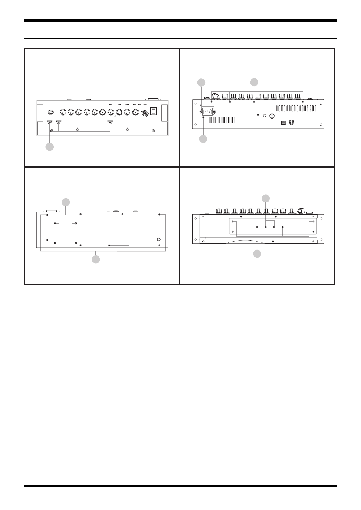
Plain View (Chassis: 1)
fig.heimenzu-chassis-1.eps
View 1 View 2
j
i
h
View 3 View 4
l
i
i
n
m
View 1
No. Part Code Part Name Description Q’ty
h 40011423 SCREW M3X6 PAN SEMS FECM 3
View 2
No. Part Code Part Name Description Q’ty
i 40012945 SCREW M3X6 PAN MACHINE W/SW+PW BZC 6
j 40011156 SCREW 3X8 FLAT TAPTITE B BZC 2
View 3
No. Part Code Part Name Description Q’ty
i 40012945 SCREW M3X6 PAN MACHINE W/SW+PW BZC 8
l 40013001 SCREW M4X8 PAN MACHINE W/SW+PW BZC 4
View 4
No. Part Code Part Name Description Q’ty
m 5100005098 SCREW 3X16 TRUSS TAPPING A BZ 3-939039-023298 6
n 40011789 NUT M3 HEX ZC 2
12
Loading...