


OWNER’S MANUAL
Thank you, and congratulations on your choice of the Roland JV-1010 64 Voice Synthesizer Module.
In order to get a good understanding of the JV-1010’s many outstanding features and ensure many years of trouble-free use, please be sure to read through this manual in its entirety.
Before using this unit, carefully read the sections entitled: “USING THE UNIT SAFELY” (p. 2–4) and “IMPORTANT NOTES” (p. 5, 6). These sections provide important information concerning the proper operation of the unit. Additionally, in order to feel assured that you have gained a good grasp of every feature provided by your new unit, Owner’s manual should be read in its entirety. The manual should be saved and kept on hand as a convenient reference.
*Apple is a registered trademark of Apple Computer, Inc.
*Macintosh is a registered trademark of Apple Computer, Inc.
*Emagic and SoundDiver are registered trademarks of Emagic GmbH.
Copyright © 1999 ROLAND CORPORATION
All rights reserved. No part of this publication may be reproduced in any form without the written permission of ROLAND CORPORATION.
For the U.K.
IMPORTANT: THE WIRES IN THIS MAINS LEAD ARE COLOURED IN ACCORDANCE WITH THE FOLLOWING CODE.
BLUE: NEUTRAL
BROWN: LIVE
As the colours of the wires in the mains lead of this apparatus may not correspond with the coloured markings identifying the terminals in your plug, proceed as follows:
The wire which is coloured BLUE must be connected to the terminal which is marked with the letter N or coloured BLACK. The wire which is coloured BROWN must be connected to the terminal which is marked with the letter L or coloured RED.
Under no circumstances must either of the above wires be connected to the earth terminal of a three pin plug.
Used for instructions intended to alert the user to the risk of death or severe injury should the unit be used improperly.
Used for instructions intended to alert the user to the risk of injury or material damage should the unit be used improperly.
* Material damage refers to damage or other adverse effects caused with respect to the home and all its furnishings, as well to domestic animals or pets.
The symbol alerts the user to important instructions or warnings.The specific meaning of the symbol is determined by the design contained within the triangle. In the case of the symbol at left, it is used for general cautions, warnings, or alerts to danger.
The  symbol alerts the user to items that must never be carried out (are forbidden). The specific thing that must not be done is indicated by the design contained within the circle. In the case of the symbol at left, it means that the unit must never be disassembled.
The ● symbol alerts the user to things that must be carried out. The specific thing that must be done is indicated by the design contained within the circle. In the case of the symbol at left, it means that the powercord plug must be unplugged from the outlet.
• Before using this unit, make sure to read the instructions below, and the Owner’s Manual.
..........................................................................................................
• Do not open or perform any internal modifications
on the unit or its AC adaptor. (The only exception would be where this manual provides specific instructions which should be followed in order to
put in place user-installable options; see p. 16.)
..........................................................................................................
•Do not attempt to repair the unit, or replace parts within it (except when this manual provides specific instructions directing you to do so). Refer all servicing to your retailer, the nearest Roland Service Center, or an authorized Roland distributor, as listed on the “Information” page.
..........................................................................................................
• Never use or store the unit in places that are:
• Subject to temperature extremes (e.g., direct sunlight in an enclosed vehicle, near a heating duct, on top of heat-generating equipment); or are
•Damp (e.g., baths, washrooms, on wet floors); or are
•Humid; or are
•Exposed to rain; or are
•Dusty; or are
•Subject to high levels of vibration.
..........................................................................................................
•This unit should be used only with a rack or stand
that is recommended by Roland.
..........................................................................................................
• When using the unit with a rack or stand recommended by Roland, the rack or stand must be carefully placed so it is level and sure to remain
stable. If not using a rack or stand, you still need to make sure that any location you choose for placing the unit provides a level surface that will properly support the unit, and keep it from wobbling.
..........................................................................................................
2
• Be sure to use only the AC adaptor supplied with
the unit. Also, make sure the line voltage at the installation matches the input voltage specified on
the AC adaptor’s body. Other AC adaptors may use a different polarity, or be designed for a
different voltage, so their use could result in damage, malfunction, or electric shock.
..........................................................................................................
•Avoid damaging the power cord. Do not bend it excessively, step on it, place heavy objects on it, etc. A damaged cord can easily become a shock or
fire hazard. Never use a power cord after it has been damaged.
..........................................................................................................
•This unit, either alone or in combination with an amplifier and headphones or speakers, may be capable of producing sound levels that could cause permanent hearing loss. Do not operate for a long period of time at a high volume level, or at a level that is uncomfortable. If you experience any hearing loss or ringing in the ears, you should immediately stop using the unit, and consult an
audiologist.
..........................................................................................................
•Do not allow any objects (e.g., flammable material, coins, pins); or liquids of any kind (water, soft
drinks, etc.) to penetrate the unit.
..........................................................................................................
• Immediately turn the power off, remove the AC adaptor from the outlet, and request servicing by your retailer, the nearest Roland Service Center, or an authorized Roland distributor, as listed on the “Information” page when:
•The AC adaptor or the power-supply cord has been damaged; or
•Objects have fallen into, or liquid has been spilled onto the unit; or
•The unit has been exposed to rain (or otherwise has become wet); or
•The unit does not appear to operate normally or exhibits a marked change in performance.
..........................................................................................................
• In households with small children, an adult
should provide supervision until the child is capable of following all the rules essential for the
safe operation of the unit.
..........................................................................................................
• Protect the unit from strong impact.
(Do not drop it!)
..........................................................................................................
•Do not force the unit’s power-supply cord to share an outlet with an unreasonable number of other devices. Be especially careful when using extension cords—the total power used by all devices you have connected to the extension cord’s outlet must never exceed the power rating (watts/
amperes) for the extension cord. Excessive loads can cause the insulation on the cord to heat up and eventually melt through.
..........................................................................................................
• Before using the unit in a foreign country, consult
with your retailer, the nearest Roland Service Center, or an authorized Roland distributor, as
listed on the “Information” page.
..........................................................................................................
• Always turn the unit off and unplug the AC
adaptor before attempting installation of the circuit board (SR-JV80 series).
..........................................................................................................
•DO NOT play a CD-ROM disc on a conventional audio CD player. The resulting sound may be of a level that could cause permanent hearing loss. Damage to speakers or other system components
may result.
..........................................................................................................
3

USING THE UNIT SAFELY
• The unit and the AC adaptor should be located so their location or position does not interfere with their proper ventilation.
..........................................................................................................
• Always grasp only the plug or the body of the AC adaptor when plugging into, or unplugging from, an outlet or this unit.
..........................................................................................................
• Whenever the unit is to remain unused for an extended period of time, disconnect the AC adaptor.
..........................................................................................................
• Try to prevent cords and cables from becoming entangled. Also, all cords and cables should be placed so they are out of the reach of children.
..........................................................................................................
•Never climb on top of, nor place heavy objects on the unit.
..........................................................................................................
• Never handle the AC adaptor body, or its plugs,
with wet hands when plugging into, or unplugging from, an outlet or this unit.
..........................................................................................................
• Before moving the unit, disconnect the AC adaptor and all cords coming from external devices.
..........................................................................................................
• Before cleaning the unit, turn off the power and unplug the AC adaptor from the outlet.
..........................................................................................................
• Whenever you suspect the possibility of lightning
in your area, disconnect the AC adaptor from the outlet.
..........................................................................................................
• Install only the specified circuit board(s) (SR-JV80 series). Remove only the specified screws (p. 16).
..........................................................................................................
4

Important Notes
In addition to the items listed under “USING THE UNIT SAFELY” on page 2, please read and
observe the following:
■Power Supply
•Do not use this unit on the same power circuit with any device that will generate line noise (such as an electric motor or variable lighting system).
•The AC adaptor will begin to generate heat after long hours of consecutive use. This is normal, and is not a cause for concern.
•Before connecting this unit to other devices, turn off the power to all units. This will help prevent malfunctions and/or damage to speakers or other devices.
■Placement
•This device may interfere with radio and television reception. Do not use this device in the vicinity of such receivers.
•To avoid possible breakdown, do not use the unit in a wet area, such as an area exposed to rain or other moisture.
■Maintenance
•For everyday cleaning wipe the unit with a soft, dry cloth or one that has been slightly dampened with water. To remove stubborn dirt, use a cloth impregnated with a mild, non-abrasive detergent. Afterwards, be sure to wipe the unit thoroughly with a soft, dry cloth.
•Never use benzine, thinners, alcohol or solvents of any kind, to avoid the possibility of discoloration and/or deformation.
■Repairs and Data
•Please be aware that all data contained in the unit’s memory may be lost when the unit is sent for repairs. Important data should always be backed up in another MIDI device (e.g., a sequencer), or written down on paper (when possible). During repairs, due care is taken to avoid the loss of data. However, in certain cases (such as when circuitry related to memory itself is out of order), we regret that it may not be possible to restore the data, and Roland assumes no liability concerning such loss of data.
■Memory Backup
•This unit contains a battery which powers the unit’s memory circuits while the main power is off. When this battery becomes weak, the message shown below will appear in the display. Once you see this message, have the battery replaced with a fresh one as soon as possible to avoid the loss of all data in memory. To have the battery replaced, consult with your retailer, the nearest Roland Service Center, or an authorized Roland distributor, as listed on the “Information” page.
fig.3-01
5

Important Notes
■Additional Precautions
•Please be aware that the contents of memory can be irretrievably lost as a result of a malfunction, or the improper operation of the unit. To protect yourself against the risk of loosing important data, we recommend that you periodically save a backup copy of important data you have stored in the unit’s memory in another MIDI device (e.g., a sequencer).
•Unfortunately, it may be impossible to restore the contents of data that was stored in the unit’s memory or another MIDI device (e.g., a sequencer) once it has been lost. Roland Corporation assumes no liability concerning such loss of data.
•Use a reasonable amount of care when using the unit’s buttons, sliders, or other controls; and when using its jacks and connectors. Rough handling can lead to malfunctions.
•When connecting / disconnecting all cables, grasp the connector itself—never pull on the cable. This way you will avoid causing shorts, or damage to the cable’s internal elements.
•To avoid disturbing your neighbors, try to keep the unit’s volume at reasonable levels. You may prefer to use headphones, so you do not need to be concerned about those around you (especially when it is late at night).
•When you need to transport the unit, package it in the box (including padding) that it came in, if possible. Otherwise, you will need to use equivalent packaging materials.
■Handling CD-ROMs
•Avoid touching or scratching the shiny underside (encoded surface) of the disc. Damaged or dirty CD-ROM discs may not be read properly. Keep your discs clean using a commercially available CD cleaner.
6

How to Read This Owner’s Manual
This owner’s manual is organized as follows.
Quick Start
This section is intended for those using the JV-1010 for the first time, and explains how to use various functions in a simple way. Please read Quick Start and follow along by actually operating the JV1010. This will help you understand most of what you need to know for basic operations.
Appendices
This chapter contains a troubleshooting section for use when the JV-1010 is not functioning as expected. There is also a list of error messages that you can refer to if an error message appears on the display. A list of patches and MIDI implementation chart are also provided.
■ Notation Used in This Owner’s Manual
An asterisk (*) at the beginning of a paragraph indicates a note or precaution. These should not be ignored. In the Quick Start section, such material is indicated by (
 ).
).
(p. **) refers to pages within the manual.
Although the JV-1010 cannot be used on its own for creating sounds, using the Emagic
SoundDiver JV/XP on the CD-ROM included with the JV-1010 allows you to create original sounds. For more on the operation of SoundDiver JV/XP, refer to SoundDiver JV/XP Help.
Furthermore, the Reference Manual that is on the included CD-ROM explains the workings of patches, performances, rhythm set parameters, and the system parameters that determine the JV1010’s operating environment, along with descriptions of the parameters. Be sure to refer to this manual this when creating sounds.
7

Contents |
|
Main Features........................................................................................ |
10 |
Front and Rear Panel............................................................................ |
11 |
Quick Start ........................................................ |
13 |
Getting Ready to Play........................................................................... |
14 |
Attaching the Rubber Feet....................................................................................................................... |
14 |
Installing on the Rack-Mount Adaptor ................................................................................................. |
14 |
Installing a Wave Expansion Board....................................................................................................... |
15 |
How to Install a Wave Expansion Board................................................................................... |
15 |
Making the Connections.......................................................................................................................... |
18 |
Switching the Power On and Off ........................................................................................................... |
20 |
Switching On the Power .............................................................................................................. |
20 |
Switching Off the Power .............................................................................................................. |
20 |
Reset to Default Factory Settings (Factory Reset) ............................ |
21 |
Listening to Demo Songs (Demo Play)............................................... |
22 |
Composer Profiles......................................................................................................................... |
23 |
Choosing and Playing Patches ........................................................... |
24 |
Auditioning Patches (Phrase Preview).................................................................................................. |
25 |
Playing Notes from a MIDI Keyboard .................................................................................................. |
26 |
Choosing Patches...................................................................................................................................... |
27 |
Choosing Patches by Bank........................................................................................................... |
27 |
Choosing Patches by Category.................................................................................................... |
28 |
Playing Percussion Sounds ..................................................................................................................... |
29 |
Using the JV-1010 as the GM Sound Module ..................................... |
31 |
Entering GM Mode................................................................................................................................... |
31 |
Changing Sounds from an External MIDI Device............................... |
32 |
Note on Using an External MIDI Device to Switch Sounds ................................................... |
32 |
Changing Patches ..................................................................................................................................... |
32 |
Changing a Performance ......................................................................................................................... |
34 |
Changing a Rhythm Set........................................................................................................................... |
36 |
Trying Out Desktop Music ................................................................... |
38 |
Connecting to a Computer...................................................................................................................... |
38 |
Connecting to the COMPUTER Connector............................................................................... |
38 |
Connecting with MIDI Connectors ............................................................................................ |
41 |
Performing Multiple Parts (Performance Mode)................................................................................. |
42 |
Editing Using Only the JV-1010........................................................... |
44 |
Making Part Settings (PART).................................................................................................................. |
44 |
Memory-Related Operations (UTILITY)............................................................................................... |
45 |
Restoring the Factory Settings (Factory Reset) ......................................................................... |
45 |
Initializing GM Mode (GM Initialize) ........................................................................................ |
46 |
Initializing the Settings (Initialize) ............................................................................................. |
47 |
Transmitting Settings to an External MIDI Device (Data Transfer) ...................................... |
48 |
Making System Settings (SYSTEM) ....................................................................................................... |
49 |
Selecting the Receive Channel (Perform Ctrl CH) ................................................................... |
49 |
Tuning (Master Tune)................................................................................................................... |
50 |
8

Contents
Appendices........................................................ |
51 |
Troubleshooting.................................................................................... |
52 |
Error Messages ..................................................................................... |
53 |
Patch List............................................................................................... |
54 |
Patch Category List .............................................................................. |
58 |
Rhythm Set List..................................................................................... |
64 |
Performance List................................................................................... |
67 |
MIDI Implementation............................................................................. |
68 |
Specifications........................................................................................ |
89 |
Computer Cable Wiring Diagrams....................................................... |
90 |
Index....................................................................................................... |
91 |
9

Main Features
■ Incorporates the JV-1080 Sound Module
The JV-1010 is a 16-part multitimbral internal sound generator that can generate up to 64 voices simultaneously, and is equipped with a multi-effects processor (EFX) offering a total of 40 different effects.
The Preset patches are compatible not only with the JV-1080 and the XP-30/50/60/80, but with the JV-2080 as well.
The General MIDI system is also supported.
General MIDI System
The General MIDI system is a set of recommendations which seeks to provide a way to go beyond the limitations of proprietary designs, and standardize the MIDI capabilities of sound generating devices. Sound generating devices and music files that meets the General MIDI standard bears the General MIDI logo (


 ). Music files bearing the General MIDI logo can be played back using any General MIDI sound generating unit to produce essentially the same musical performance (p. 31).
■ SR-JV80-09 “Session” Waves and Patch Data Onboard
There are total of 1,023 onboard sounds, including the user patches, presets A through E, and session
sounds.
■ SR-JV80 Series Wave Expansion Boards Can Be Installed
A SR-JV80 series Wave Expansion Board can be installed, enabling expansion of sounds using the SR-
JV80 series.
■ Equipped with Computer Connector
By connecting the instrument to a computer, you can enjoy full-fledged editing.
■ Easy-to-understand, Easy-to-use Operations and Other
Useful Features
You can use the CATEGORY/BANK knob to choose sounds by category.
There is a Phrase Preview that lets you audition patches through phrases, using just the JV-1010.
10
Front and Rear Panel
Front Panel
fig.0-01
1 |
2 |
3 |
4 |
5 |
6 |
7 |
8 |
9 |
1. PHONES Jack
This is the jack for connecting headphones (sold separately).
*Use headphones with an impedance of 8 to 150 Ohms.
2.VOLUME Knob
This adjusts the volume level for the OUTPUT jack and the PHONES jack. You can also check out a sound using the JV-1010 alone by pressing the VOLUME knob (Phrase Preview, p. 25). When in a mode other than the Patch mode, pressing the VALUE knob while holding down the VOLUME knob switches you to the Edit mode.
3. PART Knob
In the Patch mode, it changes the receive channel. In the Performance mode or the GM mode, it selects the Part to which settings are to be applied.
4. Display
Displays a variety of information about the operation being performed.
5. MIDI Indicator
Lights up when MIDI messages are received.
6. MODE Indicators
The indicator for the currently active mode lights up.
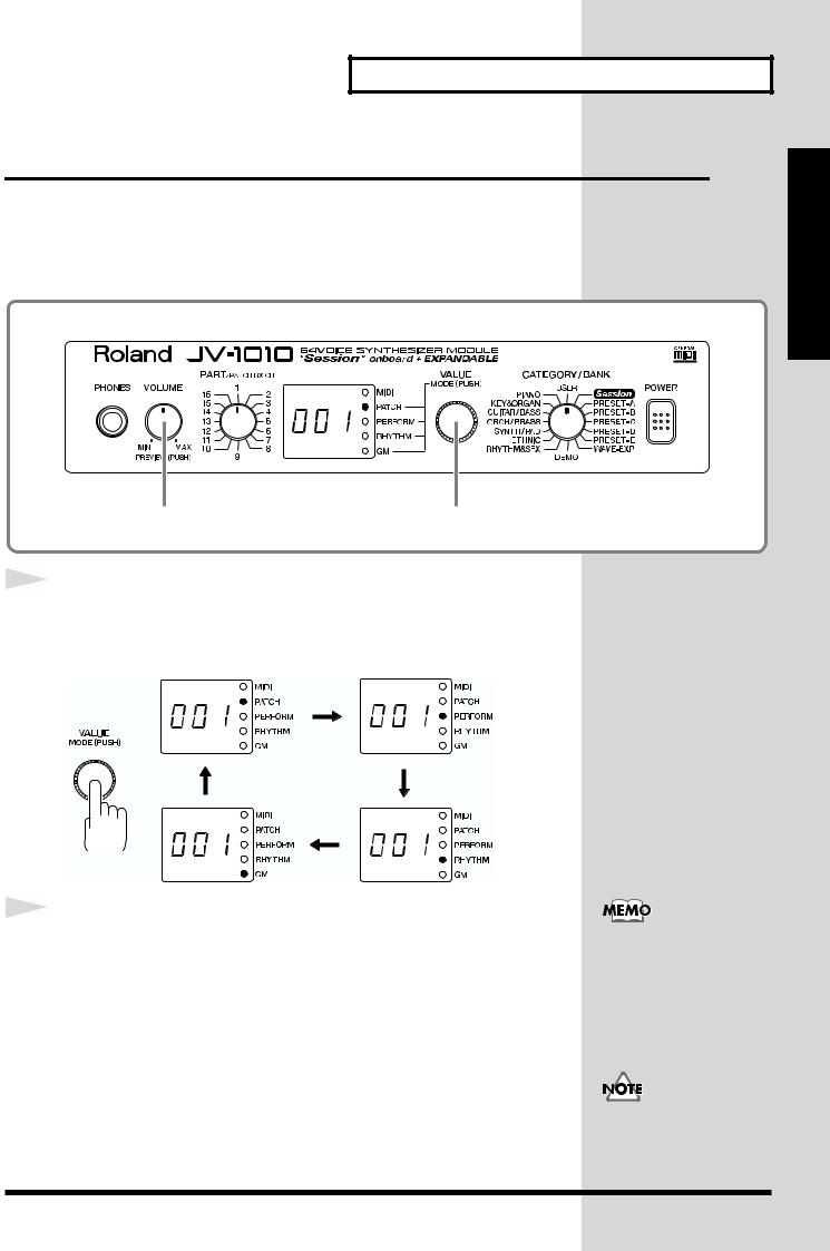
7. VALUE Knob
This changes the setting values for parameters. Turning the knob rapidly makes the value change in larger increments. Pressing the knob switches the mode. When in a mode other than the Patch mode, pressing the VALUE knob while holding down the VOLUME knob switches you to the Edit mode.
8. CATEGORY/BANK Knob
Used to switch the sound selection range. In the Edit mode, it is used to select the parameter to be set. For more information
about the CATEGORY/BANK knob’s functions in Edit mode, refer to the EDIT PARAMETER SELECT chart on the JV-1010’s top panel.
9. POWER Switch
Pressed to switch the power on and off.
11
Front and Rear Panel
Rear Panel
|
|
|
|
|
|
|
|
|
|
|
|
|
|
|
|
|
|
|
|
|
|
|
|
|
|
|
|
|
|
|
|
|
|
|
|
|
|
|
|
|
|
|
|
|
|
|
|
|
|
|
|
|
|
|
|
|
|
|
|
|
|
|
|
|
|
|
|
|
|
|
|
|
|
|
|
|
|
|
|
|
|
|
|
|
|
|
|
|
|
|
|
|
|
|
|
|
|
|
|
|
|
|
|
|
|
|
|
|
|
|
|
|
|
|
|
|
|
|
|
|
|
|
|
|
|
|
|
|
|
|
|
|
|
|
|
|
|
|
|
|
|
|
|
|
|
|
|
|
|
|
|
|
|
|
|
|
|
|
|
|
|
|
|
|
|
|
|
|
|
|
|
|
|
|
|
|
|
|
|
|
|
|
|
|
|
|
|
|
|
|
|
|
|
|
|
|
|
|
|
|
|
|
|
|
|
|
|
|
|
|
|
|
|
|
|
|
|
|
|
|
|
|
|
|
|
|
|
|
|
|
|
|
|
|
|
|
|
|
|
|
|
|
|
|
|
|
|
|
|
|
|
|
|
|
|
|
|
|
|
|
|
|
|
|
|
|
|
|
|
|
|
|
|
|
|
|
|
|
|
|
|
|
|
|
|
|
|
|
|
|
|
|
|
|
|
|
|
|
|
|
|
|
|
|
|
|
|
|
|
|
|
|
|
|
|
|
|
|
|
|
|
|
|
|
|
|
|
|
|
|
|
|
|
|
|
|
|
|
|
|
|
|
|
|
|
|
|
|
|
|
|
|
|
|
|
|
|
|
|
|
|
|
|
|
|
|
|
|
|
|
|
|
|
|
|
|
|
|
|
|
|
|
|
|
|
|
|
|
|
|
|
|
|
|
|
|
|
|
|
|
|
|
|
|
|
|
|
|
|
|
|
|
|
|
|
|
|
|
|
|
|
|
|
|
|
|
|
|
|
|
|
|
|
|
|
|
|
|
|
|
|
|
|
|
|
|
|
|
|
|
|
|
|
|
|
|
|
|
|
|
|
|
|
|
|
|
|
|
|
|
|
|
|
|
|
|
|
|
|
|
|
|
|
|
|
|
|
|
|
|
|
|
|
|
|
|
|
|
|
|
|
|
|
|
|
|
|
|
|
|
|
|
|
|
|
|
|
|
|
|
|
|
|
|
|
|
|
|
|
|
|
|
|
|
|
|
|
|
|
|
|
|
|
|
|
|
|
|
|
|
|
|
|
|
|
|
|
|
|
|
|
|
|
|
|
|
|
|
|
|
|
|
|
|
|
|
|
|
|
|
|
|
|
|
|
|
|
|
|
|
|
|
|
|
|
|
|
|
|
|
|
|
|
|
|
|
|
|
|
|
1 |
|
2 |
3 |
|
|
|
|
|
|
|
|
4 |
|
5 |
6 |
|
|
|
||||||||||||||||||||||||||||
|
|
|
|
|
|
|
|
|
|
|
|
|
|
|
|
|
|
|
|
|
|
|
|
|
|
|
|
|
|
|
|
|
|
|
|
|
|
|
|
|
|
|
|
|
|
|
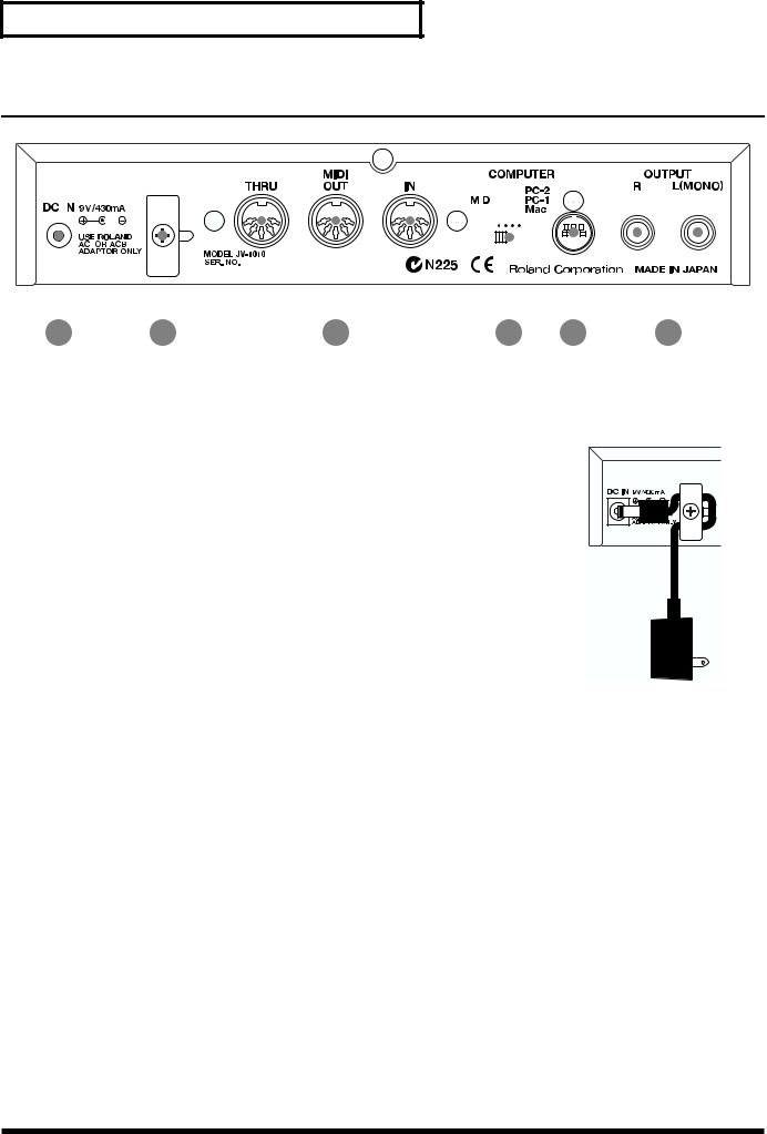
1. AC Adaptor Jack
Accepts connection of the supplied AC adapter.
2. Cord Hook
To prevent the inadvertent disruption of power to your unit (should the plug be pulled out accidentally), and to avoid applying undue stress to the AC adaptor jack, anchor the power cord using the cord hook, as shown in the illustration.
3. MIDI Connectors (IN, OUT, THRU)
These connectors are used to connect the JV-1010 with other devices for sending and receiving MIDI messages.
When using these connectors to exchange MIDI messages, set the COMPUTER switch to MIDI.
MIDI IN: This receives information from other MIDI instruments.
MIDI OUT: This sends information from the JV-1010.
MIDI THRU: This sends out, unaltered, information received from MIDI IN.
4. COMPUTER Switch (Mac, PC-1, PC-2, MIDI)
The switch should be set as appropriate for the type of computer connected to the COMPUTER
Connector, and the software being used (p. 38).
When using the MIDI connectors, set this to MIDI.
*Turn off the power before changing this switch’s setting.
5.COMPUTER Connector
This is for connecting a computer to the JV-1010 using a computer cable (sold separately) (p. 38). Set the COMPUTER switch to Mac or PC-2.
6. OUTPUT Jacks (L (MONO), R)
These are for stereo (L/R) output of audio signals to an amp or a mixer. For monaural output, connect to the left (L) jack.
12

Quick Start
Quick Start
13
Getting Ready to Play
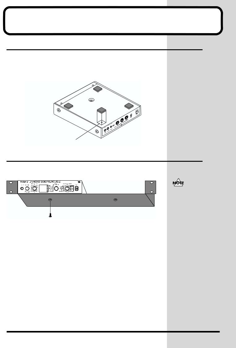
Attaching the Rubber Feet
If you will not be using the separately available RAD-50 rack-mount adaptor, attach the rubber feet that were supplied with the JV-1010, as shown in the figure. Use the small holes on the bottom as a guide for positioning the rubber feet when attaching them.
fig.1-01.e
affix the supplied rubber feet onto the bottom of the unit
Installing on the Rack-Mount Adaptor
When installing on the rack-mount adaptor (RAD-50; sold separately), use
the screw (M4 x 8) included with the rack-mount adaptor.
fig.1-02.e
Screw (M4 x 8)
When mounting the unit using the rack-mount adaptor, install it onto the rack-mount adaptor without attaching the rubber feet.
14

Getting Ready to Play
Installing a Wave Expansion Board
One Wave Expansion Board (SR-JV80 series; sold separately) can be installed in the JV-1010.
Waveform data, patches and rhythm sets are stored on the Wave Expansion Board, so you can increase the number of available sounds by installing the board in the JV-1010.
The Wave Expansion Board can be installed by removing the top cover.
■ How to Install a Wave Expansion Board
First, here are some important points to remember when installing into the JV-1010:
●To avoid the risk of damage to internal components that can be caused by static electricity, please carefully observe the following whenever you handle the board.
•Before you touch the board, always first grasp a metal object (such as a water pipe), so you are sure that any static electricity you might have been carrying has been discharged.
•When handling the board, grasp it only by its edges. Avoid touching any of the electronic components or connectors.
•Save the bag in which the board was originally shipped, and put the board back into it whenever you need to store or transport it.
●Do not touch any of the printed circuit pathways or connection terminals.
●Never use excessive force when installing a circuit board. If it doesn’t fit properly on the first attempt, remove the board and try again.
●When circuit board installation is complete, double-check your work.
●Install only the specified board, and remove only the specified screws.
●Be careful not to cut your hands on the opening for installing the board.
Installing a Wave Expansion Board increases the patches and drum sets for Parts, but the number of Parts doesn’t change.
Quick Start
15
Getting Ready to Play
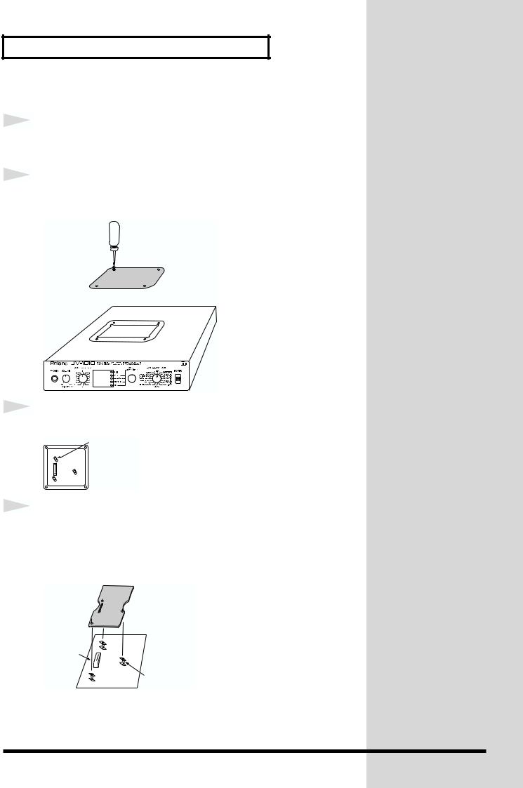
Follow the steps below to install the Wave Expansion Board.
1
2
fig.1-03a.e
3
fig.1-03b.e
4
fig.1-03c.e
Before installing the Wave Expansion Board, switch off the power to the JV-1010 and any connected equipment.
Detach the cover on the upper portion of the JV-1010. Loosen the four screws on the upper portion of the cover.
 Screwdriver
Position the board holders so they are oriented.
Board holder
Insert the connector for the Wave Expansion Board into the connector on the unit, and at the same time, fit the board holders into the holes. When you do this, the heads of the three board holders should protrude from the Expansion Board.
Connector
EXP-B |
Board holder |
16
Getting Ready to Play
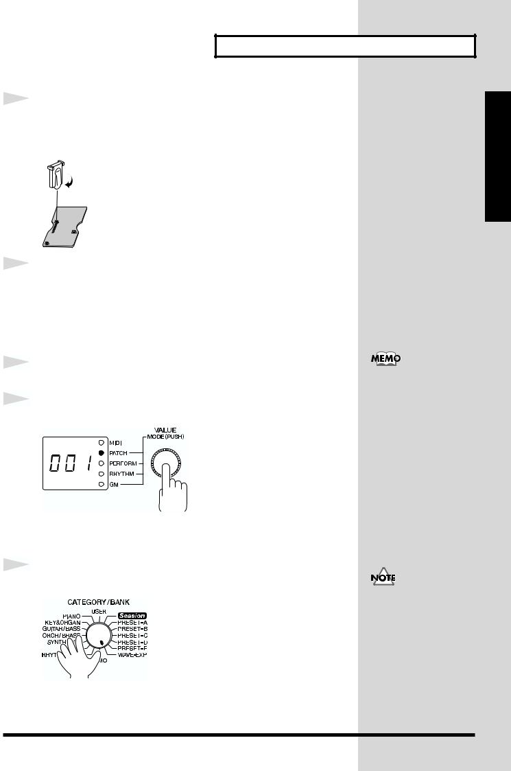
5 |
|
Use the tool supplied with the Wave Expansion Board to |
|
|
|
||
|
|
rotate the board holders to LOCK, securing the Wave |
|
|
|
Expansion Board in place. |
|
fig.1-03d.e |
|
|
|
|
|
LOCK |
|
|
|
|
|
6 |
Use the (specified) screws you removed in step 2 to reattach |
|
|
|
the cover. |
1
2
fig.1-04
3
fig.1-05
This completes the installation of the Wave Expansion Board. Next, make
sure the board is installed correctly.
Switch on the power to the JV-1010 (p. 20).
Press the VALUE knob to choose the Patch mode (PATCH).
Pressing the VALUE knob makes the mode change sequentially. Press the
knob several times, until the PATCH indicator lights up.
Turn the CATEGORY/BANK knob to choose WAVE-EXP.
If 001 appears in the display, the Wave Expansion Board has been installed
correctly.
When a Wave Expansion Board is installed, then when you switch on the power first roland Jv-1010 is displayed, and after that the final two digits of the model number for the installed Wave Expansion Board flash twice on the display.
For example, when the SR- JV80-02 “Orchestral” Wave Expansion Board is installed, 02 flashes twice on the display.
If the display shows - - -, it’s likely that the Wave Expansion Board is not being recognized correctly. Follow the steps in
“Switching Off the
Power” (p. 20) to switch off the power, then reinstall the Wave Expansion Board, making sure you do it correctly.
Quick Start
17

Getting Ready to Play
Making the Connections
The JV-1010 does not have a built-in amp or speakers. In order to produce sound, you need to hook up audio equipment such as a monitor speaker or a stereo set, or use headphones.
fig.1-06.e
Headphones
AC adaptor
COMPUTER connector
DC IN
MIDI IN
MIDI keyboard
MIDI OUT 
MIDI OUT 
MIDI sequencer etc.
Mixer etc. |
Monitor speakers |
|
|
(powered) |
Stereo set etc. |
|
|
|
|
|
|
|
|
|
|
|
|
|
|
|
|
|
|
|
|
|
|
|
|
|
|
|
|
|
|
|
|
|
|
|
|
|
|
|
|
|
|
|
Cassette radio |
|
|
|
|
|
Power amp |
|
|
|
|
|
|
|
18

1
2
3
Getting Ready to Play
Follow the steps described below to connect the JV-1010 and an external
device.
Before making the connections, make sure the power to all equipment is switched off.
Connect the included AC adaptor to the AC adaptor jack and plug the adaptor into a power outlet.
Connect the JV-1010 and the external device as shown in the figure.
Connecting audio equipment: the OUTPUT jacks (L (MONO), R)
Use audio cables (sold separately) to connect the audio device to the
OUTPUT jacks on the JV-1010.
Connecting a MIDI keyboard or sequencer: the MIDI connectors (IN,
OUT, THRU)
Use a MIDI cable (sold separately) to connect the MIDI OUT connector on the MIDI keyboard or sequencer to the MIDI IN connector on the JV-1010.
Using headphones: the PHONES jack
Plug the headphones (sold separately) into the PHONES jack on the front panel.
Using a computer: the COMPUTER connector
Use a computer cable (sold separately) to connect the computer to the COMPUTER connector on the JV-1010.
To prevent malfunction and/or damage to speakers or other devices, always turn down the volume, and turn off the power on all devices before making any connections.
We recommend using a stereo connection in order to get the maximum performance from the JV1010, but for monaural use, make the connection to the L (MONO) OUTPUT jack.
For more information on making the connection with the computer, take a look at “Connecting to a
Computer” (p. 38).
Quick Start
19
Getting Ready to Play
Switching the Power On and Off
■Switching On the Power
1Before you switch on the power, check the following.
•Are peripheral devices connected correctly?
•Is the volume level on the JV-1010 and the connected external equipment turned down all the way?
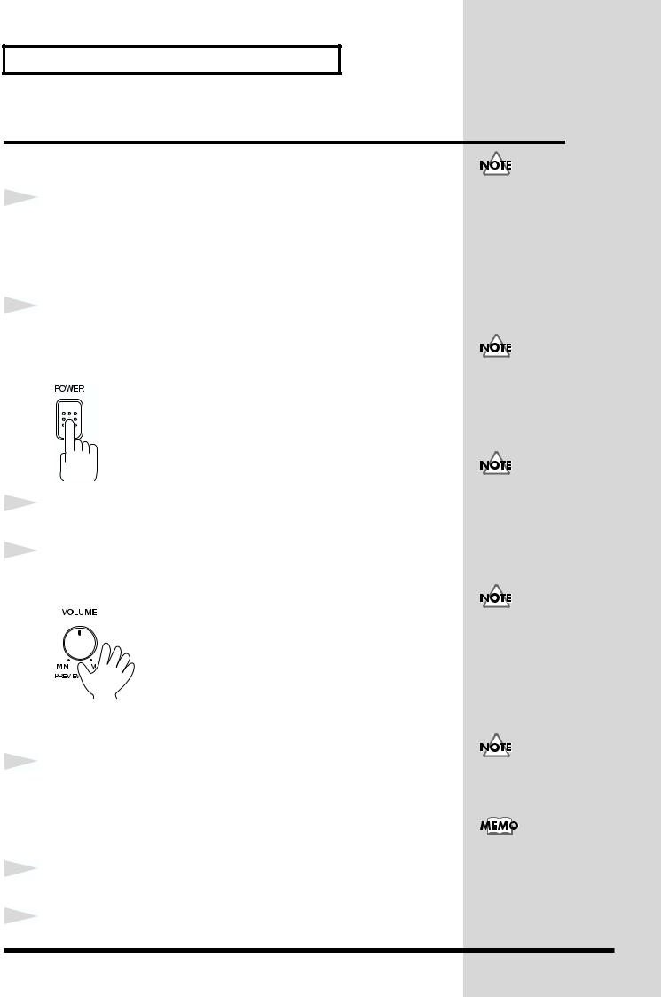
2Press the POWER switch on the JV-1010 to switch on the power.
After roland Jv-1010 is displayed, the unit starts up in the same state it was
in when the power was last turned off.
¬fig.1-07
Once the connections have been completed (p. 18), turn on power to your various devices in the order specified. By turning on devices in the wrong order, you risk causing malfunction and/or damage to speakers and other devices.
If the power was turned off while in the Rhythm Set mode (RHYTHM), the unit starts up in the Performance mode (PERFORM).
3 |
|
Switch on the power to the connected external equipment. |
|||
|
|
||||
|
|
|
|
|
|
4 |
|
Play sounds on the JV-1010 and turn the VOLUME knob to |
|||
|
|
||||
|
|
adjust the volume on the JV-1010 and the external equipment. |
|||
fig.1-08 |
|
|
|
|
|
|
|
|
|
|
|
|
|
|
|
|
|
|
|
|
|
|
|
|
|
|
|
|
|
|
|
|
|
|
|
■Switching Off the Power
1Before you switch off the power, check the following.
•Is the volume level on the JV-1010 and the connected external equipment turned down all the way?
•Have you saved the sounds or other data you’ve created? (p. 48)
2Switch off the power to the connected external equipment.
3Switch off the POWER switch on the JV-1010.
This unit is equipped with a protection circuit. A brief interval (a few seconds) after power up is required before the unit will operate normally.
Be careful not to turn the volume up too high. Excessive volume levels are not only inconsiderate to others around you, but may damage external equipment or cause hearing loss.
Turning the VOLUME knob up all the way may result in distortion for some sounds.
You can also play sounds on just the unit itself by pressing the VOLUME knob (Phrase Preview, p.
20
Reset to Default Factory Settings (Factory Reset)
When using the JV-1010 for the first time, start by returning the settings to their factory defaults so that the JV-1010 operates as described in the procedures in the owner’s manual.
This returns all settings stored in memory in the JV-1010 to the values they had when the unit was shipped from the factory.
fig.1-09
1
2
3
4
fig.Sur
5
2 |
1,4,5 |
3 |
Press the VALUE knob to switch to a mode other than the Patch mode (PATCH), that is, to the PERFORM, RHYTHM, or
GM mode.
While holding down the VOLUME knob, press the VALUE knob.
Switch to the Edit mode.
Turn the CATEGORY/BANK knob to choose PIANO (Factory Reset).
Fct flashes on the display.
In the Edit mode, choosing PIANO (Factory Reset) with the CATEGORY/ BANK knob makes it possible to perform Factory Reset.
Press the VALUE knob.
Sur flashes on the display, prompting you to confirm that you indeed wish to carry out a Factory Reset.
Press the VALUE knob.
The Factory Reset is performed, and you leave the Edit mode.
If there is important data you’ve created that’s stored in memory, all such data is discarded, and everything is returned to the factory defaults when a Factory Reset is performed. If important data is stored in the unit, save it on an external MIDI device (p. 48).
When in the Patch mode, you can’t enter the Edit mode.
For more information about the CATEGORY/ BANK knob’s other functions in Edit mode, refer to the EDIT
PARAMETER SELECT
chart on the JV-1010’s top panel.
To exit from the Edit mode without carrying out a Factory Reset, follow the same procedure as in step 2.
Quick Start
21
Listening to Demo Songs (Demo Play)
The JV-1010 comes with four demonstration songs.
Here’s how to start Demo Play, and listen to the outstanding sounds of the JV-1010.
Song Name |
Composer/Copyright |
||||
All In Good Time |
Scott Wilkie © 1999 Scott Wilkie Media (ASCAP) |
||||
Guitars Forever |
Gundy Keller © 1999 Gundy Keller / A-TOWN recordings |
||||
Rude99 |
Hans-Joerg Scheffler © 1999 Hans Scheffler |
||||
Overtime |
Hans-Joerg Scheffler © 1999 Hans Scheffler |
||||
fig.1-10 |
|
|
|
|
|
|
|
|
|
|
|
|
|
|
|
|
|
All rights reserved. Unauthorized use of this material for purposes other than private, personal enjoyment is a violation of applicable laws.
3 2,3
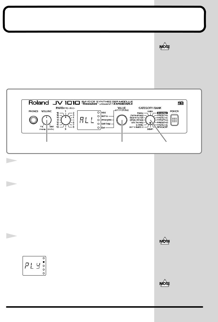
1 |
|
Turn the CATEGORY/BANK knob to choose DEMO. |
|
|
|
||
|
|
ALL flashes on the display. |
|
|
|
|
|
2 |
|
Turn the VALUE knob to choose the song you want to hear. |
|
|
|
||
|
|
You can choose ALL, d-1, d-2, d-3, or d-4. |
|
|
|
ALL: the songs will playback successively, beginning from the first. |
|
|
|
d-1: All In Good Time |
|
|
|
d-2: Guitars Forever |
|
|
|
d-3: Rude99 |
|
|
|
d-4: Overtime |
|
|
|
|
|
3 |
|
Press the VALUE knob or the VOLUME knob. |
|
|
|
||
|
|
The display shows Ply and Demo Play starts. |
|
fig.1-10a |
|
|
|
|
|
|
|
After a demo song has played all the way to the end, the unit automatically returns to the start of the song and playback is repeated. To end Demo Play partway through a song, press the VALUE knob or the VOLUME knob, or turn the CATEGORY/BANK knob.
1
MIDI messages received from external instruments are ignored while the Demo Play screen is displayed.
No data for the music that is played will be output from MIDI OUT.
22

Listening to Demo Songs (Demo Play)
■ Composer Profiles
Scott Wilkie
Scott Wilkie is a contemporary jazz recording artist, based in southern California. He tours frequently with his own band, and also appears as an artist for Roland in the U.S., Japan, Europe and South America. His debut solo album, Boundless, was released worldwide in 1999 on Narada/Virgin Records. You can find him on-line at www.scottwilkie.com.
Gundy Keller
Gundy Keller, a Germany-based guitarist, songwriter and producer, has been an international demonstrator for Roland since 1986. Gundy focuses mainly on the GR synthesizers and the V-Guitar, for international music conventions as well as recording sessions requesting completely unusual guitar sounds. Besides creating his own production company, he’s the founder and director of Rocksound Music School, a private institute for music instruction. Check out some of his other work on the Roland VG-8 Demo CD, or the Roland GR-30 Video.
Hans-Joerg Scheffler
Born and raised in the Ruhr valley, the biggest industrial area in Germany, Hans’s attraction to noise and rhythm came naturally.
Today he runs his own company, DIGITAL AUDIO DESIGN, which produces sampling CDs and CD ROMs.
He works for Roland as a pro audio product specialist, as a sound designer for expansion boards, and as a composer of demo songs. He has released several CDs that use the Roland RSS system. Soundclips of his work can be downloaded at: http://www.united-sound.com/usmaster/ cell2downde.htm
Quick Start
23

Choosing and Playing Patches
The JV-1010 comes with a large number of onboard sounds. On the JV-1010, the sounds used for an ordinary performance are called Patches.
With the JV-1010, you can use seven groups—User, Preset A through E, and Session—and when a Wave Expansion Board (separately available) is installed, you can also use the Wave Expansion Board’s onboard patches.
USER
There are 128 patches stored in memory, which you can overwrite with patches you create yourself.
PRESET-A–C, E
There are 512 patches stored in memory, which cannot be overwritten.
PRESET-D (GM [General MIDI])
These are patches for the General MIDI System, which is designed to standardize the specifications for MIDI functions for all manufacturers and models. There are 128 patches stored in memory, which cannot be overwritten.
Session
Already onboard is the data from the SR-JV80-09 Wave Expansion Board, which offers a selection of 255 patches, which cannot be overwritten.
WAVE-EXP (Wave Expansion Board installed in the slot)
Patches are stored in memory on the separately available Wave Expansion
Board, and cannot be overwritten.
When using software for external MIDI devices, tone editors, and the like, you can transmit System Exclusive messages to rewrite USER content.
You can’t choose a WAVEEXP patch unless a Wave Expansion Board is installed in the slot EXP-B. When no Wave Expansion Board is installed, - - -
appears on the display.
24
Choosing and Playing Patches
Auditioning Patches (Phrase Preview)
On the JV-1010, you can check out patches easily, since phrases are provided for each type of patch. Thanks to this, you don’t need to have a MIDI keyboard or sequencer connected.
In this section, we’ll listen to patch sounds in the Patch mode.
fig.1-11
2 1
1 |
Press the VALUE knob to choose the Patch mode (PATCH). |
|
Pressing the VALUE knob makes the mode change sequentially. Press the
knob several times, until the PATCH indicator lights up.
fig.1-12
2 |
Holding down the VOLUME knob, the sound for the currently |
|
|
|
selected patch is played. |
Right after returning settings to their factory defaults, the first patch of the currently selected Category and Bank (CATEGORY/BANK) plays.
Some patches may not be sounded in a suitable range.
Quick Start
25
Choosing and Playing Patches
Playing Notes from a MIDI Keyboard
The JV-1010 receives and plays MIDI data from other instruments. When doing this, the transmitting instrument (the MIDI keyboard or the like) and the JV-1010 must be set to the same MIDI channel.
Here we’ll play sounds with both channels set to 1.
fig.1-13
1
2
4 |
3 |
Connect a MIDI keyboard to the JV-1010 (p. 18).
Set the transmit channel for the MIDI keyboard (the transmitting instrument) to 1.
For information on how to make the settings, refer to the owner’s manual for the MIDI keyboard.
3
4
5
fig.1-14
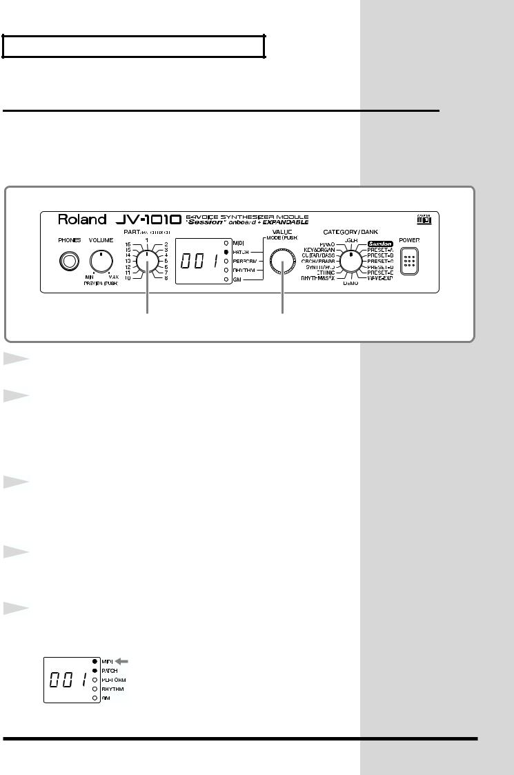
Press the VALUE knob to choose the Patch mode (PATCH).
Pressing the VALUE knob makes the mode change sequentially. Press the
knob several times, until the PATCH indicator lights up.
Turn the PART knob and choose 1.
Here, 1 becomes the JV-1010’s receive channel.
Finger some keys on the MIDI keyboard to play a few notes.
When MIDI data is received, the MIDI indicator lights up.
26

Choosing and Playing Patches
Choosing Patches
When you’ve selected the Patch mode or the Performance mode, after changing the Category and Bank with the CATEGORY/BANK knob, you can choose a patch by turning the VALUE knob.
You can use either of two methods to choose
a patch: choosing by bank (display with white text) or choosing by category (display in blue text).
■ Choosing Patches by Bank |
by category |
by bank |
|
|
In this section, let’s choose No. 108 Flute from USER (the User group).
You can’t choose a WAVEEXP patch unless a Wave Expansion Board is installed in the slot EXP-B. When no Wave Expansion Board is installed, - - -
appears on the display.
fig.1-16
4 1,3 2
1 |
Press the VALUE knob to choose the Patch mode (PATCH). |
|
|
|
Pressing the VALUE knob makes the mode change sequentially. Press the |
|
knob several times, until the PATCH indicator lights up. |
|
|
2 |
Turn the CATEGORY/BANK knob to choose USER. |
|
|
|
|
3 |
Turn the VALUE knob and choose 108. |
|
|
|
|
4 |
You can listen to the selected patch sound (USER No. 108 |
|
|
|
Flute) by holding down the VOLUME knob. |
|
At this time, the currently selected preset bank USr (USER) and the patch |
|
number 108 appear in alternation on the display. |
fig.1-16a
Turning the VALUE knob rapidly makes the value change in large increments.
For more information about the onboard patches, take a look at “Patch List”
(p. 54).
Quick Start
27
Choosing and Playing Patches
■ Choosing Patches by Category
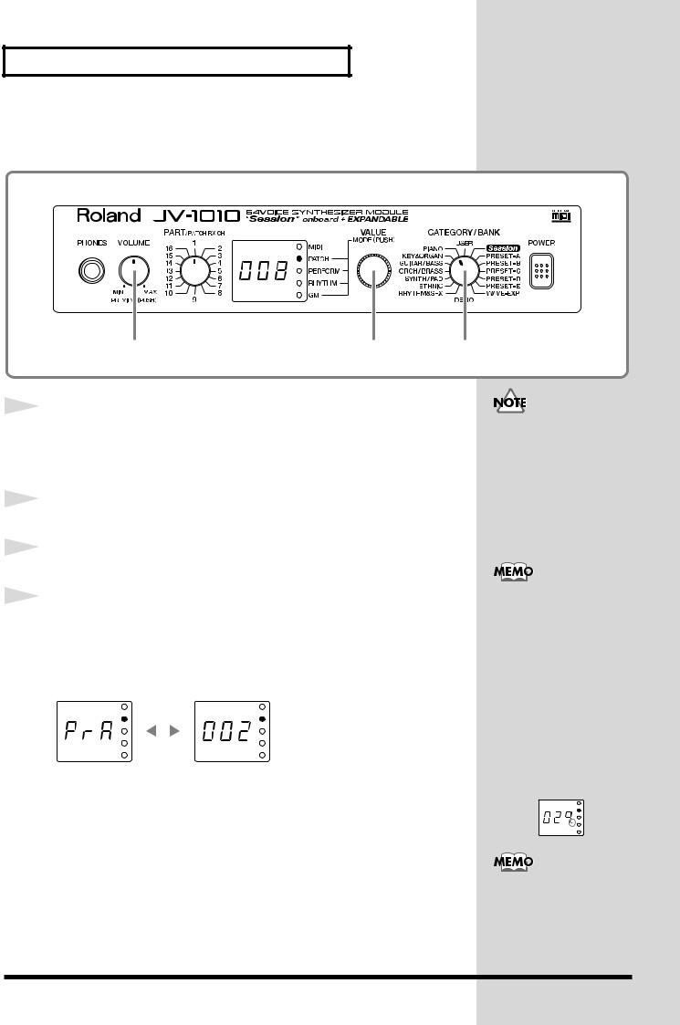
Here, let’s choose No. 008 Bright Piano from PIANO (the Piano category).
fig.1-17
4 1,3 2
1 |
|
Press the VALUE knob to choose the Patch mode (PATCH). |
|||
|
|
||||
|
|
Pressing the VALUE knob makes the mode change sequentially. Press the |
|||
|
|
knob several times, until the PATCH indicator lights up. |
|||
|
|
|
|
|
|
2 |
|
Turn the CATEGORY/BANK knob to choose PIANO. |
|||
|
|
||||
|
|
|
|
|
|
3 |
|
Turn the VALUE knob to choose 008. |
|||
|
|
||||
|
|
|
|
|
|
4 |
|
You can listen to the selected patch sound (PIANO No. 008 |
|||
|
|
||||
|
|
Bright Piano) by holding down the VOLUME knob. |
|||
|
|
At this time, the currently selected bank PrA (PRESET-A) and the patch |
|||
|
|
number 002 appear in alternation on the display. |
|||
fig.1-18a |
|
|
|
|
|
|
|
|
|
|
|
|
|
|
|
|
|
|
|
|
|
|
|
When you release the VOLUME knob, the display shows the patch number
008 of the category group PIANO.
The patches you can choose by category are Preset A, B, C, D, and E, and Session (XP-A) patches. The sounds and categories of User and WAVE-EXP (XP-B) patches vary, so you can’t choose these patches by category.
Turning the VALUE knob rapidly makes the value change in large increments. Also, turning the VALUE knob while pressing it in jumps you to the value at the start of each category, in the currently selected category group. The start values for by-category patches are shown with a dot at the end of the number on the display.
For more information
about the by-category
patches, take a look at
“Patch Category List” (p.
58).
28

Choosing and Playing Patches
Playing Percussion Sounds
The JV-1010 has Rhythm Sets that contain a variety of percussion instruments and special effects sounds.
With the JV-1010, you can use seven groups—User, Preset A through E, and Session—and when a Wave Expansion Board (separately available) is installed, you can also use the Wave Expansion Board’s onboard rhythm sets.
USER
There are 2 rhythm sets stored in memory, which you can overwrite with patches you create yourself.
PRESET-A–C, E
There are 8 rhythm sets stored in memory, which cannot be overwritten.
PRESET-D (GM [General MIDI])
These are rhythm sets for the General MIDI System, which is designed to standardize the specifications for MIDI functions for all manufacturers and models. There are 2 rhythm sets stored in memory, which cannot be overwritten.
Session
Already onboard is the data from the SR-JV80-09 Wave Expansion Board, which offers a selection of 8 rhythm sets, which cannot be overwritten.
WAVE-EXP (Wave Expansion Board installed in the slot)
Patches are stored in memory on the separately available Wave Expansion
Board, and cannot be overwritten.
When using software for external MIDI devices, tone editors, and the like, you can transmit System Exclusive messages to rewrite USER content.
You can’t choose a WAVEEXP patch unless a Wave Expansion Board is installed in the slot EXP-B. When no Wave Expansion Board is installed, - - -
appears on the display.
Quick Start
29
 Loading...