


SP 8300DN
Table of contents
 Loading...
Model AL-P2
Machine Code: M132
Field Service Manual
July, 2012


Safety Notices
Important Safety Notices
Prevention of Physical Injury
1. Before disassembling or assembling parts of the main machine and peripherals, make sure that the
power cord of the main machine is unplugged.
2. The wall outlet should be near the machine and easily accessible.
3. Note that some components of the machine and the paper tray unit are supplied with electrical
voltage even if the main power switch is turned off.
4. If any adjustment or operation check has to be made with exterior covers off or open while the
main switch is turned on, keep hands away from electrified or mechanically driven components.
5. If the Start key is pressed before the machine completes the warm-up period (the Start key starts
blinking red and green alternatively), keep hands away from the mechanical and the electrical
components as the machine starts making prints as soon as the warm-up period is completed.
6. The inside and the metal parts of the fusing unit become extremely hot while the machine is
operating. Be careful to avoid touching those components with your bare hands.
• To prevent a fire or explosion, keep the machine away from flammable liquids, gases, and
aerosols.
Health Safety Conditions
1. Toner and developer are non-toxic, but if you get either of them in your eyes by accident, it may
cause temporary eye discomfort. Immediately wash eyes with plenty of water. If unsuccessful, get
medical attention.
2. This machine, which uses a high voltage power source, can generate ozone gas. High ozone
density is harmful to human health. Therefore, the machine must be installed in a well-ventilated
room.
Observance of Electrical Safety Standards
1. This machine and its peripherals must be serviced by a customer service representative who has
completed the training course on those models.
2. The NVRAM on the system control board has a lithium battery which can explode if replaced
incorrectly. Replace the NVRAM only with an identical one. The manufacturer recommends
1

replacing the entire NVRAM. Do not recharge or burn this battery. Used NVRAM must be handled
in accordance with local regulations.
Handling Toner
• Work carefully when removing paper jams or replacing toner bottles or cartridges to avoid spilling
toner on clothing or the hands.
• If toner is inhaled, immediately gargle with large amounts of cold water and move to a well
ventilated location. If there are signs of irritation or other problems, seek medical attention.
• If toner gets on the skin, wash immediately with soap and cold running water.
• If toner gets into the eyes, flush the eyes with cold running water or eye wash. If there are signs of
irritation or other problems, seek medical attention.
• If toner is swallowed, drink a large amount of cold water to dilute the ingested toner. If there are
signs of any problem, seek medical attention.
• If toner spills on clothing, wash the affected area immediately with soap and cold water. Never use
hot water! Hot water can cause toner to set and permanently stain fabric.
• Always store toner and developer supplies such as toner and developer packages, cartridges, and
bottles (including used toner and empty bottles and cartridges) out of the reach of children.
• Always store fresh toner supplies or empty bottles or cartridges in a cool, dry location that is not
exposed to direct sunlight.
• Do not use a vacuum cleaner to remove spilled toner (including used toner). Vacuumed toner may
cause a fire or explosion due to sparks or electrical contact inside the cleaner. However, it is
possible to use a cleaner designed to be dust explosion-proof. If toner is spilled over the floor,
sweep up spilled toner slowly and clean up any remaining toner with a wet cloth.
Safety and Ecological Notes for Disposal
1. Do not incinerate toner bottles or used toner. Toner dust may ignite suddenly when exposed to an
open flame.
2. Dispose of used toner, the maintenance unit which includes developer or the organic
photoconductor in accordance with local regulations. (These are non-toxic supplies.)
3. Dispose of replaced parts in accordance with local regulations.
4. When keeping used lithium batteries in order to dispose of them later, do not put more than 100
batteries per sealed box. Storing larger numbers or not sealing them apart may lead to chemical
reactions and heat build-up.
2

Laser Safety
The Center for Devices and Radiological Health (CDRH) prohibits the repair of laser-based optical units
in the field. The optical housing unit can only be repaired in a factory or at a location with the requisite
equipment. The laser subsystem is replaceable in the field by a qualified Customer Engineer. The laser
chassis is not repairable in the field. Customer engineers are therefore directed to return all chassis and
laser subsystems to the factory or service depot when replacement of the optical subsystem is required.
• Use of controls, or adjustment, or performance of procedures other than those specified in this
manual may result in hazardous radiation exposure.
• Turn off the main switch before attempting any of the procedures in the Laser Optics Housing Unit
section. Laser beams can seriously damage your eyes.
CAUTION MARKING:
3
Conventions in this Manual
Symbols and Abbreviations
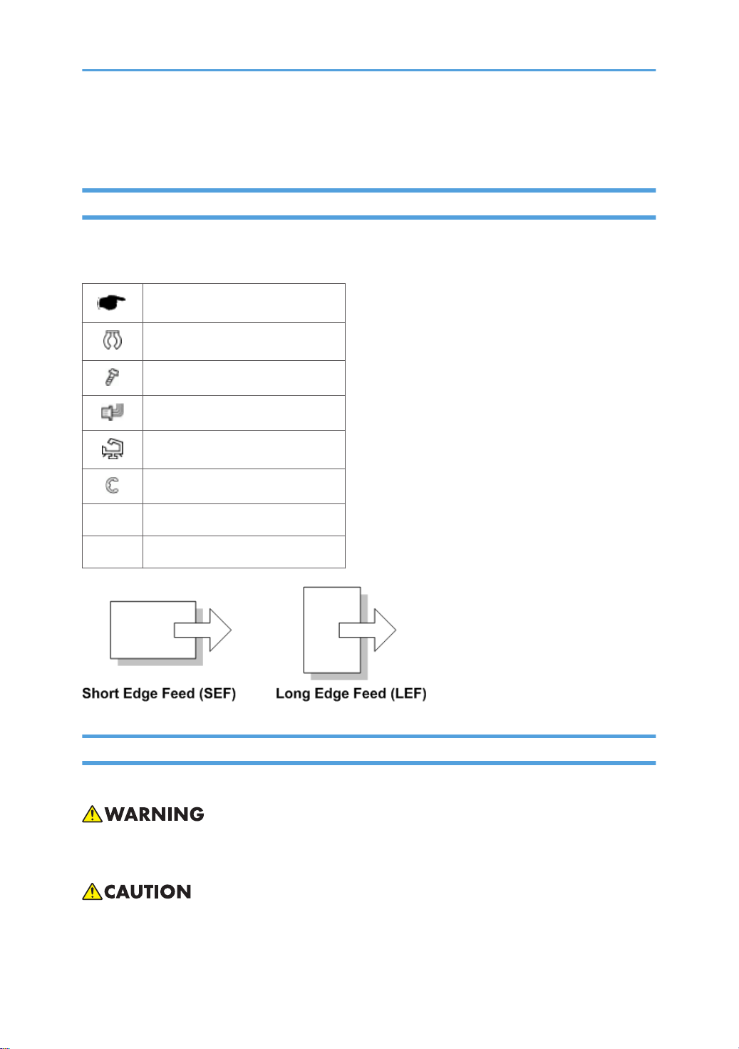
This manual uses several symbols and abbreviations. The meaning of those symbols and abbreviations
are as follows:
See or Refer to
Clip ring
Screw
Connector
Clamp
E-ring
SEF Short Edge Feed
LEF Long Edge Feed
Cautions, Notes, etc.
The following headings provide special information:
• FAILURE TO OBEY WARNING INFORMATION COULD RESULT IN SERIOUS INJURY OR
DEATH.
• Obey these guidelines to ensure safe operation and prevent minor injuries.
4

• This information provides tips and advice about how to best service the machine.
5

TABLE OF CONTENTS
Safety Notices.....................................................................................................................................................1
Important Safety Notices............................................................................................................................... 1
Safety and Ecological Notes for Disposal................................................................................................... 2
Laser Safety.....................................................................................................................................................3
Conventions in this Manual................................................................................................................................4
Symbols and Abbreviations...........................................................................................................................4
Cautions, Notes, etc.......................................................................................................................................4
1. Product Information
Specifications....................................................................................................................................................13
Machine Configuration....................................................................................................................................14
Printer............................................................................................................................................................ 14
Guidance for Those Who are Familiar with Predecessor Products..............................................................16
Overview.......................................................................................................................................................... 17
Component Layout.......................................................................................................................................17
Paper Path.................................................................................................................................................... 18
Drive Layout..................................................................................................................................................19
2. Installation
Installation Requirements................................................................................................................................. 21
Environment..................................................................................................................................................21
Machine Level..............................................................................................................................................22
Minimum Space Requirements................................................................................................................... 22
Power Requirements.................................................................................................................................... 23
Main Machine Installation...............................................................................................................................24
Installation Overview...................................................................................................................................24
Power Socket for Peripheral........................................................................................................................25
Installation Flow Chart.................................................................................................................................26
Moving the Machine................................................................................................................................... 26
Transporting the Machine........................................................................................................................... 26
1200-sheet LCT Installation (D631)...............................................................................................................28
Component Check.......................................................................................................................................28
Installation Procedure..................................................................................................................................28
Side Fence Position Change....................................................................................................................... 31
Bridge Unit Installation (D634).......................................................................................................................33
6

Component Check.......................................................................................................................................33
Installation Procedure..................................................................................................................................33
1000-sheet Finisher (D588)........................................................................................................................... 39
Accessory Check..........................................................................................................................................39
Installation Procedure..................................................................................................................................40
3000-sheet Finisher (D636)........................................................................................................................... 43
Accessory Check..........................................................................................................................................43
Installation Procedure..................................................................................................................................44
Punch Unit Installation (D570)........................................................................................................................ 49
Component Check.......................................................................................................................................49
Installation Procedure..................................................................................................................................50
Output Jogger Unit Installation (B703).......................................................................................................... 55
Accessory Check List....................................................................................................................................55
Installation Procedure..................................................................................................................................55
Tray Heater.......................................................................................................................................................58
Installation Procedure..................................................................................................................................58
Tray Heater (Optional Paper Feed Unit)........................................................................................................60
Component Check.......................................................................................................................................60
Installation Procedure..................................................................................................................................60
External USB Keyboard Installation............................................................................................................... 68
Installation Procedure..................................................................................................................................68
Controller Options............................................................................................................................................70
Overview...................................................................................................................................................... 70
Application Merge...................................................................................................................................... 73
3. Preventive Maintenance
PM Tables......................................................................................................................................................... 77
4. Replacement and Adjustment
General Cautions.............................................................................................................................................79
Laser Unit...................................................................................................................................................... 79
Used Toner................................................................................................................................................... 79
Special Tools and Lubricants...........................................................................................................................80
Special Tools................................................................................................................................................80
Lubricants......................................................................................................................................................80
7

Exterior Covers................................................................................................................................................. 81
Front Door, Upper and Lower Inner Cover............................................................................................... 81
Left Cover......................................................................................................................................................82
Rear Cover................................................................................................................................................... 82
Right Rear Cover..........................................................................................................................................83
Top Right and Top Rear Cover................................................................................................................... 84
Operation Panel...........................................................................................................................................84
Paper Exit Cover.......................................................................................................................................... 86
Output Tray.................................................................................................................................................. 87
Laser Unit.......................................................................................................................................................... 89
Caution Decal Locations............................................................................................................................. 89
Laser Unit...................................................................................................................................................... 90
Polygon Mirror Motor................................................................................................................................. 91
Laser Synchronization Detector..................................................................................................................91
LD Unit...........................................................................................................................................................92
PCDU.................................................................................................................................................................95
PCDU (Photoconductor and Development Unit).......................................................................................95
Drum..............................................................................................................................................................96
Pick-off Pawls................................................................................................................................................98
Charge Roller and Cleaning Roller............................................................................................................ 99
Drum Cleaning Blade................................................................................................................................100
ID Sensor....................................................................................................................................................100
Development.................................................................................................................................................. 102
Development Filter.....................................................................................................................................102
Development Roller...................................................................................................................................102
Developer.................................................................................................................................................. 105
TD Sensor...................................................................................................................................................107
Transfer...........................................................................................................................................................109
Transfer Belt Unit........................................................................................................................................109
Transfer Belt............................................................................................................................................... 109
Toner Overflow Sensor.............................................................................................................................112
Transfer Belt Cleaning Blade....................................................................................................................112
Paper Feed..................................................................................................................................................... 113
8

Paper Feed Unit.........................................................................................................................................113
Pick-Up, Feed and Separation Rollers.....................................................................................................114
Tray Lift Motor............................................................................................................................................115
Relay, Tray Lift, Paper End and Paper Feed Sensors............................................................................. 115
Registration Sensor....................................................................................................................................116
Fusing..............................................................................................................................................................119
Fusing Unit..................................................................................................................................................119
Web Roller Unit......................................................................................................................................... 119
Brake Pad...................................................................................................................................................120
Web Holder Roller and Web Rollers...................................................................................................... 121
Pressure Roller Cleaning Roller................................................................................................................ 124
Thermostats................................................................................................................................................ 125
Thermistor...................................................................................................................................................126
Hot Roller Strippers................................................................................................................................... 126
Fusing Lamps..............................................................................................................................................127
Hot Roller and Pressure Roller..................................................................................................................129
Paper Exit........................................................................................................................................................131
Paper Exit Unit........................................................................................................................................... 131
Fusing Exit, Paper Overflow, and Paper Exit Sensors............................................................................ 131
Junction Jam Sensor.................................................................................................................................. 132
Paper Exit Motor........................................................................................................................................132
Duplex............................................................................................................................................................ 134
Duplex Unit................................................................................................................................................ 134
Right Door Cover.......................................................................................................................................137
Duplex Door Sensor..................................................................................................................................137
Duplex Entrance Sensor............................................................................................................................138
Duplex Exit Sensor.................................................................................................................................... 139
Duplex/By-pass Motor.............................................................................................................................141
Duplex Inverter Motor...............................................................................................................................142
By-pass........................................................................................................................................................... 144
By-pass Paper Size Sensor/By-pass Paper Length Sensor................................................................... 144
By-pass Paper End Sensor........................................................................................................................146
By-pass Pick-up, Feed and Separation Roller, Torque Limiter...............................................................147
9

By-pass Feed Clutch..................................................................................................................................148
Drive Area...................................................................................................................................................... 149
Paper Feed Clutch.....................................................................................................................................149
Development Paddle Motor..................................................................................................................... 149
Transfer/Development Motor..................................................................................................................150
Drum Motor............................................................................................................................................... 151
Fusing Motor..............................................................................................................................................151
Web Motor................................................................................................................................................152
Paper Feed Motor..................................................................................................................................... 153
Transfer Belt Contact Motor..................................................................................................................... 153
Registration Motor.....................................................................................................................................154
Toner Supply Motor.................................................................................................................................. 154
Electrical Components...................................................................................................................................156
Controller Unit........................................................................................................................................... 156
Controller Board........................................................................................................................................156
After Installing the Controller Board........................................................................................................ 159
Mother Board............................................................................................................................................ 159
BCU............................................................................................................................................................ 162
Bridge Board............................................................................................................................................. 164
IOB............................................................................................................................................................. 164
PSU............................................................................................................................................................. 165
High Voltage Power Supply..................................................................................................................... 165
Fusing Exhaust Fan.................................................................................................................................... 166
Controller Fan............................................................................................................................................166
SD USB Board........................................................................................................................................... 167
LCDC Board...............................................................................................................................................168
Print Adjustments............................................................................................................................................ 170
Overview....................................................................................................................................................170
Printing........................................................................................................................................................170
Touch Screen Calibration......................................................................................................................... 174
5. Service Tables
Service Program Mode.................................................................................................................................177
Service Program Mode Operation..........................................................................................................177
10

Service Program Mode Tables.................................................................................................................177
Service Program Mode Tables.....................................................................................................................179
SP Tables....................................................................................................................................................179
Service Main SP Tables.................................................................................................................................180
SP1-xxx...................................................................................................................................................... 180
Engine Main SP Tables-1..............................................................................................................................189
SP1-xxx: Feed............................................................................................................................................189
Engine Main SP Tables-2..............................................................................................................................198
SP2-xxx: Drum...........................................................................................................................................198
Engine Main SP Tables-3..............................................................................................................................203
SP3-xxx: Process....................................................................................................................................... 203
Engine Main SP Tables-4..............................................................................................................................204
Engine Main SP Tables-5..............................................................................................................................205
SP5-xxx: Mode..........................................................................................................................................205
Engine Main SP Tables-6..............................................................................................................................252
SP6-xxx: Peripherals................................................................................................................................. 252
Engine Main SP Tables-7..............................................................................................................................259
SP7-xxx: Data Log.....................................................................................................................................259
Engine Main SP Tables-8..............................................................................................................................273
SP8-XXX: Data Log2................................................................................................................................. 273
Engine Main SP Tables-9..............................................................................................................................296
Input Check Table..................................................................................................................................... 296
Output Check Table.................................................................................................................................. 305
3000-Sheet Finisher (D636)....................................................................................................................311
Updating the Firmware..................................................................................................................................313
Before You Begin.......................................................................................................................................313
Updating Firmware................................................................................................................................... 313
Handling Firmware Update Errors...........................................................................................................316
Uploading/Downloading NVRAM Data....................................................................................................318
Uploading NVRAM Data (SP5-824)......................................................................................................318
Downloading NVRAM Data (SP5-825).................................................................................................319
Self-Diagnostic Mode................................................................................................................................... 321
Self-Diagnostic Mode at Power On.........................................................................................................321
11

Self-Diagnostic Test Flow..........................................................................................................................322
Detailed Self-Diagnostic Mode................................................................................................................323
Using the Debug Log.....................................................................................................................................324
Overview....................................................................................................................................................324
Switching On And Setting Up Save Debug Log..................................................................................... 324
SMC List Card Save Function....................................................................................................................... 330
Overview....................................................................................................................................................330
Procedure...................................................................................................................................................330
File Names of the Saved SMC Lists......................................................................................................... 332
Error Messages..........................................................................................................................................333
6. Troubleshooting
Service Call Conditions.................................................................................................................................335
Summary.................................................................................................................................................... 335
SC Code Descriptions...............................................................................................................................336
Electrical Component Defects.......................................................................................................................397
Sensors....................................................................................................................................................... 397
Switches..................................................................................................................................................... 400
Blown Fuse Conditions.................................................................................................................................. 401
Fuses............................................................................................................................................................... 402
7. Energy Saving
Energy Save................................................................................................................................................... 403
Energy Saver Modes................................................................................................................................ 403
Energy Save Effectiveness........................................................................................................................ 404
Paper Save.....................................................................................................................................................406
Effectiveness of Duplex/Combine Function............................................................................................ 406
12

1. Product Information
Specifications
See "Appendices" for the following information:
• General Specifications
• Optional Equipment
13
1. Product Information
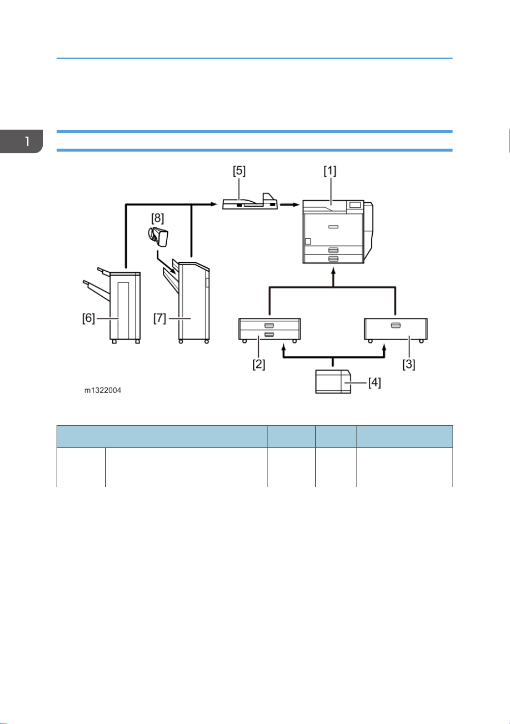
Machine Configuration
Printer
Key: Symbol: U: Unique option, C: Option also used with other products
Item Callout Key Machine Code
Main
Frame
14
M132 [1] - M132

Item Callout Key Machine Code
Two-Tray Paper Feed Unit [2] C D580
2000-sheet LCT [3] C D581
1200-sheet LCT [4] C D631
Bridge Unit [5] C D634
1000-sheet Finisher (See Note 1) [6] C D588
Machine Configuration
External
Options
Internal
Options
3000-Sheet Finisher (See Note 1) [7] C D636
-Punch Unit (See Note 2) - C
-Punch Unit (See Note 2) - C
-Punch Unit (See Note 2) - C
D570-00 (2/3-hole)
(NA)
D570-01 (2/4-hole)
(EU)
D570-02 (4-hole)
(Scandinavia)
-Output Jogger Unit (See Note 2) [8] C B703
HDD - U M416
Memory Unit 512 MB - C D594
IPDS Unit - C M416
Netware - C M416
VM Card - C D640
Font SD Card - C D641 (EU)
G874 (EU)
Gigabit Ethernet - C
M394 (NA)
IEEE 802.11a/g, g - C M344
IEEE 1284 - C B679
NOTE:
1. The finisher requires the bridge unit and two-tray paper feed unit or 2000-sheet LCT. The 1000sheet finisher and 3000-sheet finisher cannot be installed together.
2. The punch unit and output jogger unit requires the 3000-sheet finisher.
15

1. Product Information
Guidance for Those Who are Familiar with Predecessor Products
The M132 series are successor models to the G179 series. If you have experience with the predecessor
products, the following information will be of help when you read this manual.
Different Points from Predecessor Products
M132 G179
Controller Type GW+ Controller GW Controller
Operation Panel 4.3” touch panel includes USB/SD
slot
USB2.0/SD Slot Standard Not supported
Light Detect Function Available Not supported
SMC data SD card down load or printing Printing only
Safety Shut Down
Function
PDF Direct Standard Not supported
Data Overwrite Security Standard Option
HDD Encryption Standard Option
Available Not Available
4-line LCD
16
Overview
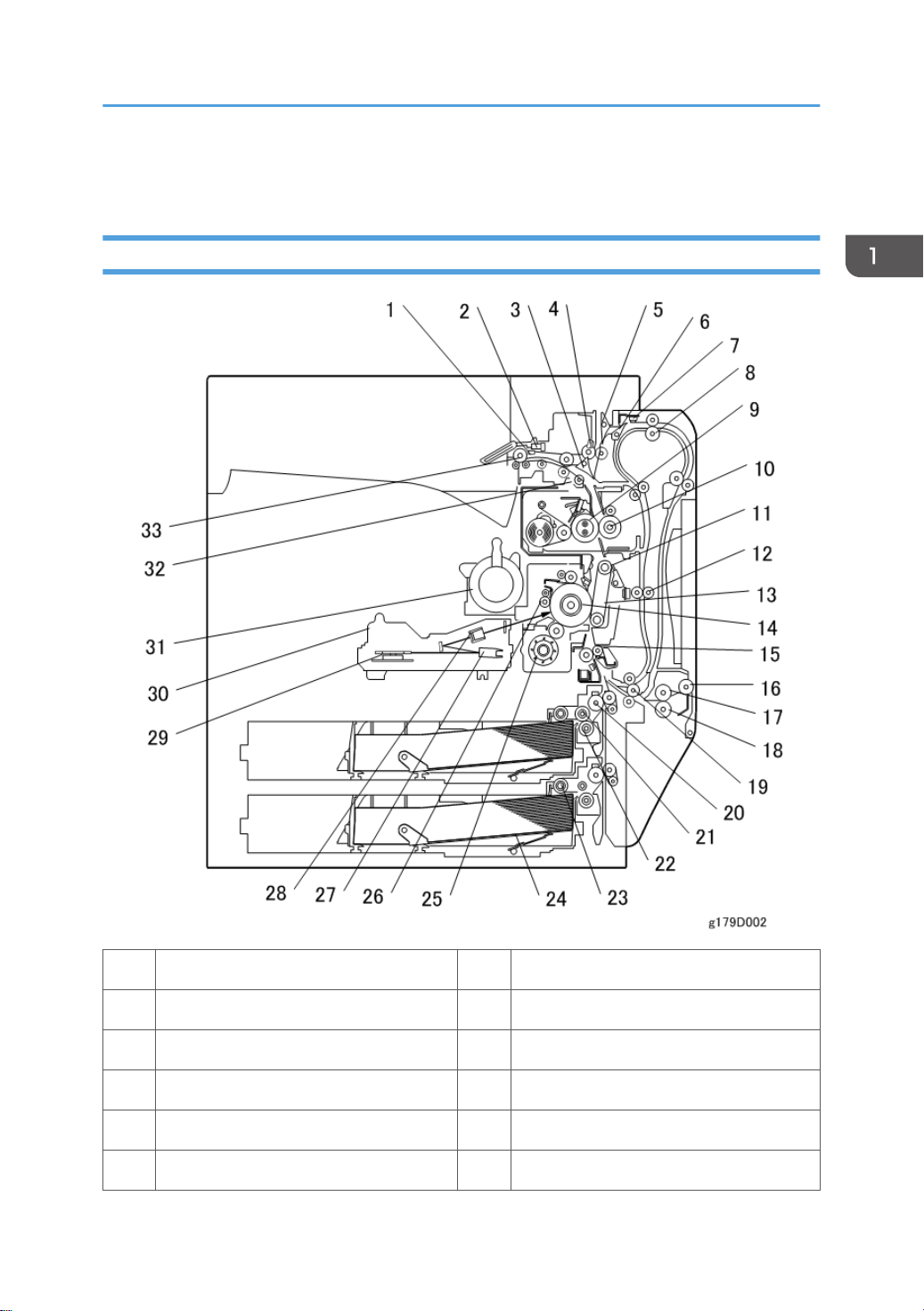
Component Layout
Overview
1 Paper Exit Sensor 17 By-pass Feed Roller
2 Paper Overflow Sensor 18 By-pass Separation Roller
3 Junction Gate 1 19 Duplex/by-pass transport roller
4 Junction Jam Sensor 20 Upper Relay Belt
5 Duplex Inverter Gate 21 Feed Roller
6 Junction Gate 2 22 Separation Roller
17
1. Product Information
7 Duplex Entrance Sensor 23 Pick-up Roller
8 Duplex Inverter Roller 24 Bottom Plate
9 Hot Roller 25 Development Unit
10 Pressure Roller 26 Charge Roller
11 Transfer Belt Cleaning Blade 27 F Mirror
12 Duplex Transport Roller 28 Barrel Toroidal Lens (BTL)
13 Transfer Belt 29 Polygonal Mirror Motor
14 OPC Drum 30 Laser Unit
15 Registration Roller 31 Toner Bottle Holder
16 By-pass Pick-up Roller 32 Fusing Exit Sensor
33 Exit Roller
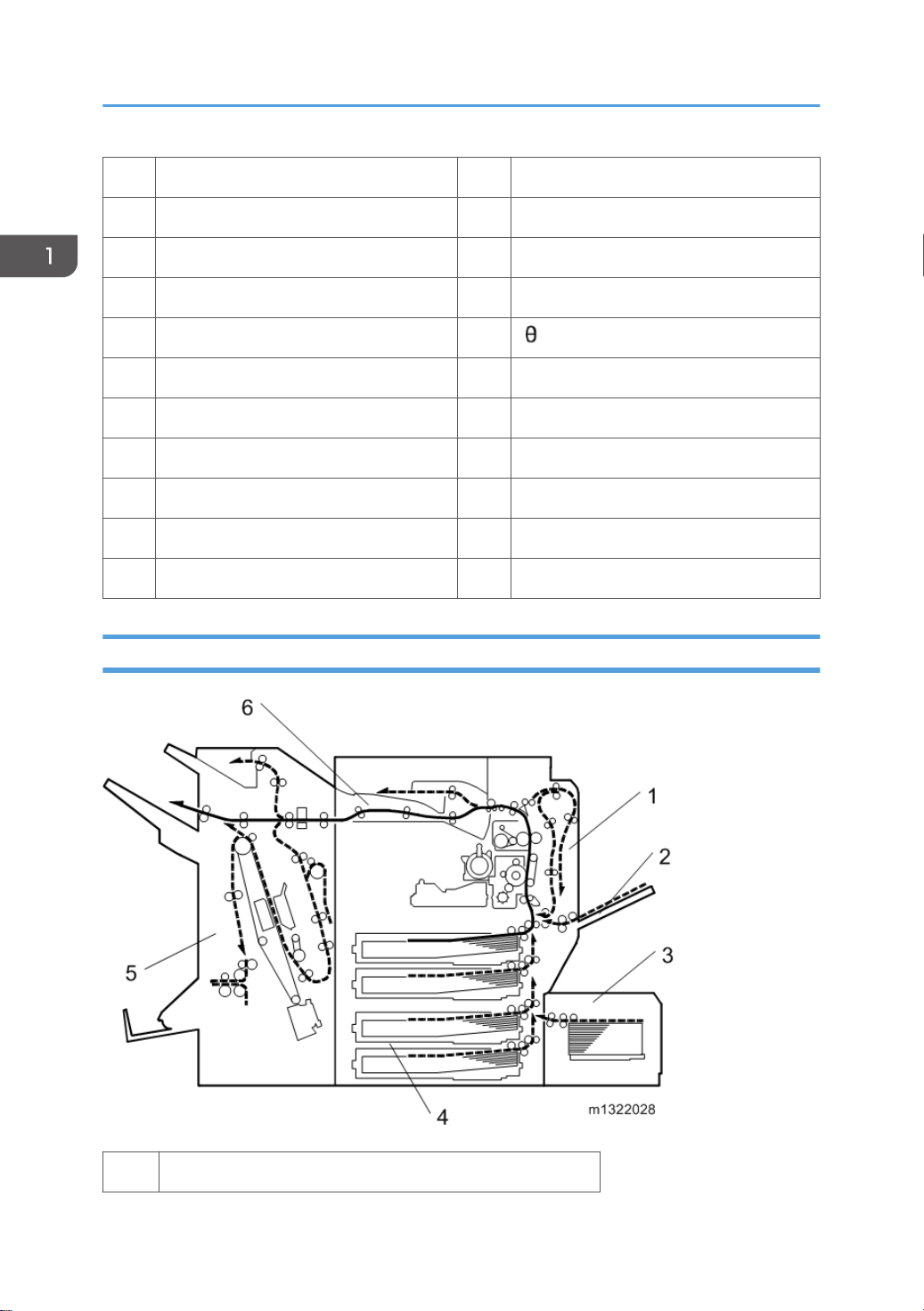
Paper Path
18
1 Duplex Unit
2 By-pass Tray
3 Large Capacity Tray (LCT: 1200-sheet)
4 Paper Tray Unit
5 Two-Tray Finisher
6 Bridge Unit
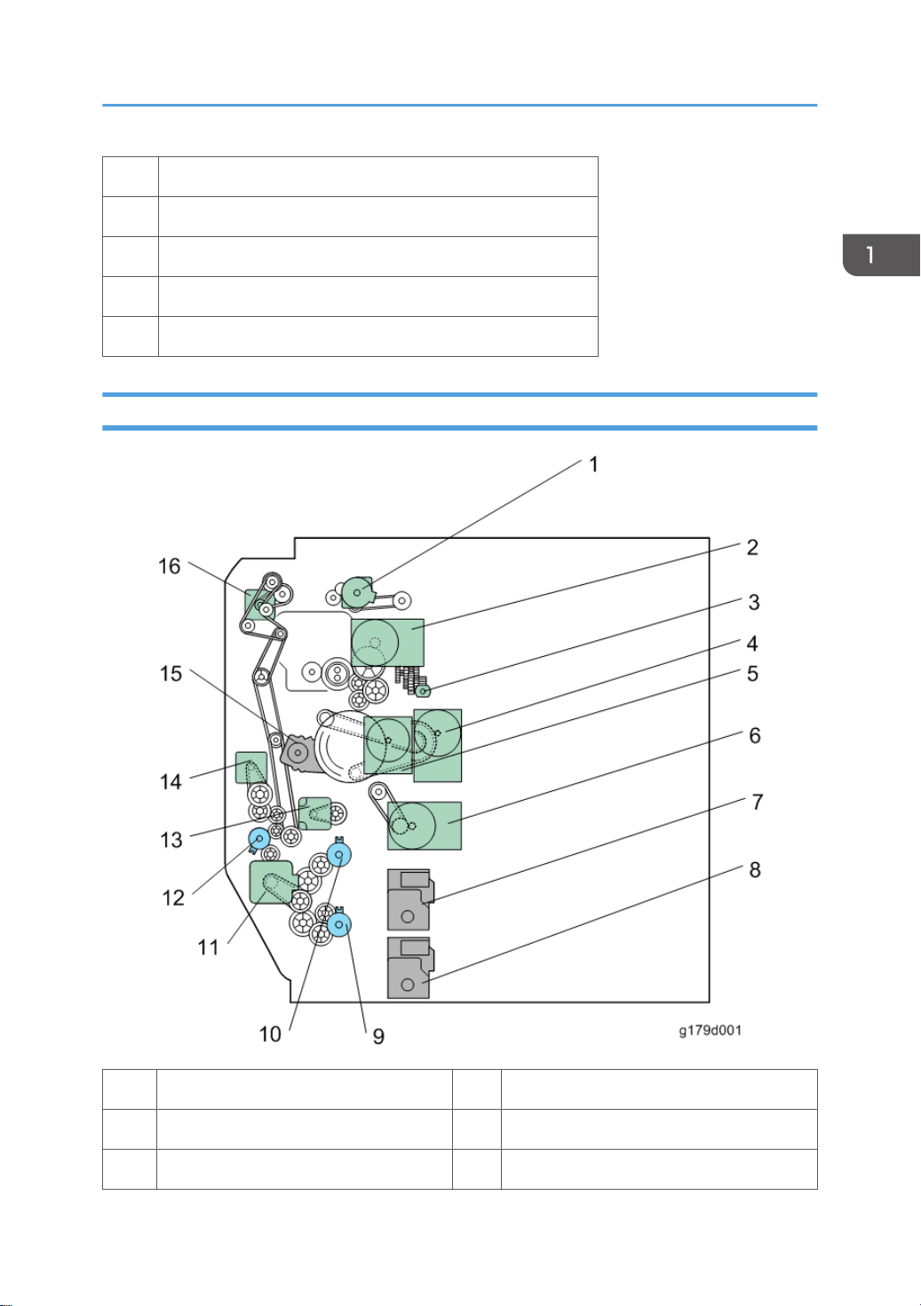
Drive Layout
Overview
1 Paper Exit Motor 9 Paper Feed Clutch 2
2 Fusing Motor 10 Paper Feed Clutch 1
3 Web Motor 11 Feed Motor
19

1. Product Information
4 Transfer/Development Motor 12 By-pass Paper Feed Clutch
5 Drum Motor 13 Registration Motor
6 Development Paddle Motor 14 Duplex/By-pass Motor
7 Tray Lift Motor 1 15 Transfer Belt Contact Motor
8 Tray Lift Motor 2 16 Duplex Inverter Motor
20
2. Installation
Installation Requirements
• Install the machine in a safe place for keeping security.
• Make sure that the operation instructions are kept at a customer's hand.
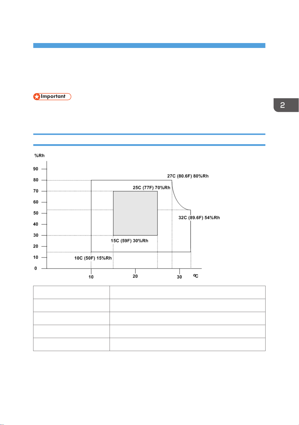
Environment
Temperature Range: 10°C to 32°C (50°F to 90°F)
Humidity Range: 15% to 80% RH
Ambient Illumination: Less than 1,500 lux (do not expose to direct sunlight.)
Ventilation: Room air should turn at least 30 m3/hr/person
Ambient Dust: Less than 0.10 mg/m3 (2.7 x 10/6 oz/yd3)
21
2. Installation
1. Avoid areas exposed to sudden temperature changes:
1) Areas directly exposed to cool air from an air conditioner.
2) Areas directly exposed to heat from a heater.
2. Do not place the machine where it will be exposed to corrosive gases.
3. Do not install the machine at any location over 2,000 m (6,500 ft.) above sea level.
4. Place the main machine on a strong and level base. Inclination on any side should be no more
than 5 mm (0.2").
5. Do not place the machine where it may be subjected to strong vibrations.
Machine Level
Front to back: Within 5 mm (0.2") of level
Right to left: Within 5 mm (0.2") of level
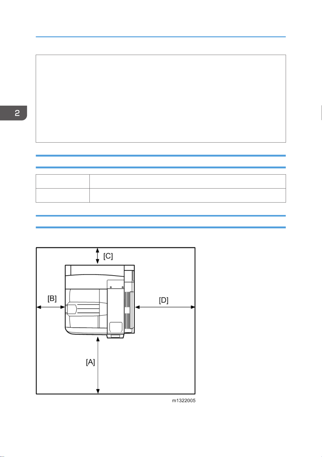
Minimum Space Requirements
Place the main machine near the power source, providing clearance as shown:
22
• Front [A]: Over 75 cm (29.6")
Installation Requirements
• Left [B]: 10 cm (4")
• Rear [C]: 10 cm (4")
• Right [D]: 55 cm (21.7")
• The 75 cm (29.6") recommended for the space at the front is for pulling out the paper tray only. If
the operator stands at the front of the main machine, more space is required.
Power Requirements
• Make sure that the wall outlet is near the main machine and easily accessible. Make sure the plug
is firmly inserted in the outlet.
• Avoid multi-wiring.
• Be sure to ground the machine.
1. Input voltage level:
North America 120 V to 127 V, 60 Hz: More than 12 A
Europe/Asia 220 V to 240V, 50 Hz/60 Hz: More than 7 A
2. Permissible voltage fluctuation:
For printing images For operating
North America +8.66 / -10 % +8.66 / -15 %
Others +/-10 % +/-15 %
3. Never set anything on the power cord.
23

2. Installation
Main Machine Installation
Installation Overview
The installation procedures of the following items are in the Operating Instructions:
Main Machine and Hardware Options
• Printer M132 (main machine) Installation
• Paper Feed Unit: D580
• LCIT PB3140: D581
Controller Options
• HDD: M416
• Data Storage Card: D594
• IEEE1284 Interface Board: B679
• IEEE802.11a/g Interface Unit: M344
• Gigabit Ethernet: G874 (EU only), M394 (NA only)
• VM Card: D640
• IPDS Unit: M416
• SD Card for Netware Printing: M416
• SD Card for fonts: D641 (EU only)
• The bridge unit (D634) and either the 2,000-sheet LCT (D581) or the paper tray (D580) must be
installed before the finisher SR3120 (D636) or SR3090 (D588) is installed.
The installation procedures of the following options are in this service manual:
Hardware Options
• LCIT RT3020: D631
• Bridge Unit: D634 (for Finisher SR3120 and SR3090)
• Finisher SR3120: D636
• Punch Unit: D570 (for Finisher SR3120)
• Jogger Unit: B703 (for Finisher SR3120)
• Finisher SR3090: D588
24
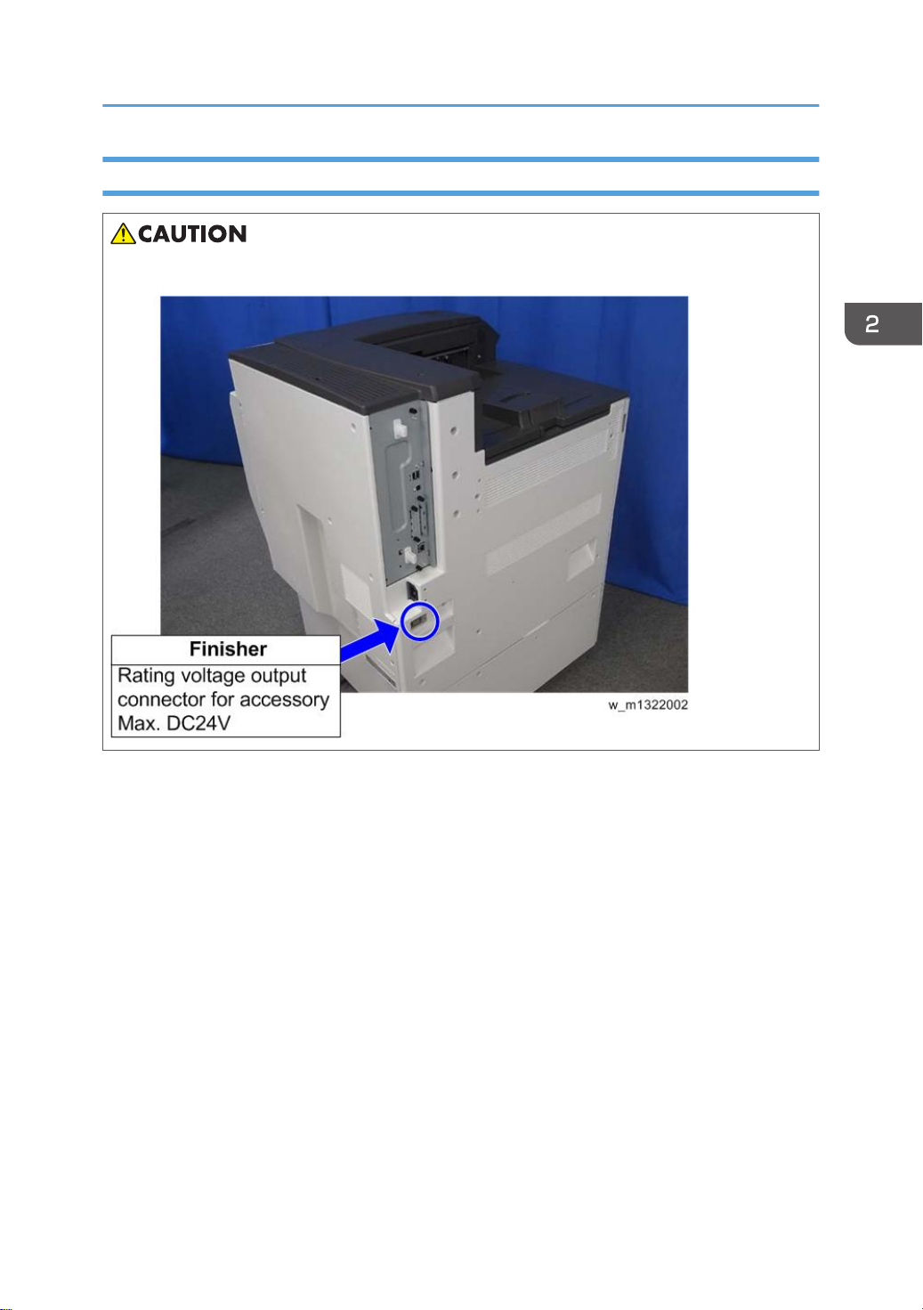
Power Socket for Peripheral
• Rating voltage for peripheral: Make sure to plug the cable into the correct socket.
Main Machine Installation
25
2. Installation
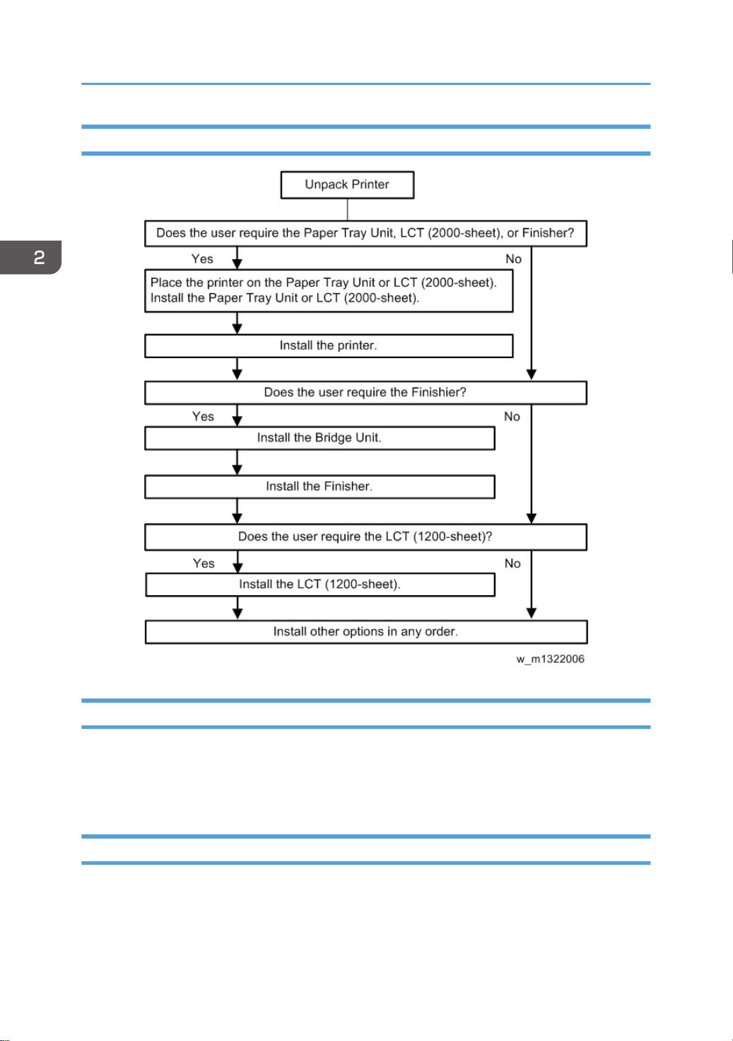
Installation Flow Chart
Moving the Machine
This section shows you how to manually move the machine from one floor to another floor. See the
section "Transporting the Machine" if you have to pack the machine and move it a longer distance.
1. Remove all trays from the optional paper feed unit or LCT.
Transporting the Machine
1. Make sure there is no paper left in the paper trays. Then fix down the bottom plates with a sheet of
paper and tape.
2. Do one of the following:
26

• Attach shipping tape to the covers and doors.
• Shrink-wrap the machine tightly.
Main Machine Installation
27
2. Installation
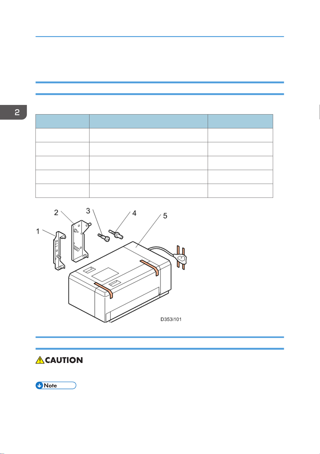
1200-sheet LCT Installation (D631)
Component Check
Check the quantity and condition of the components against the following list.
No. Description Q'ty
1 Front Bracket 1
2 Rear Bracket 1
3 Stud Screw 4
4 Joint Pin 2
5 LCT 1
Installation Procedure
• Unplug the main machine power cord before starting the following procedure.
• The Paper Tray Unit (D580) or LCT 2000-sheet (D581) must be installed before installing this
1200-sheet LCT.
28
Loading...