

Page 1
20-430 .fm Page 1 Wednesday, A ugust 4, 1999 1:29 PM
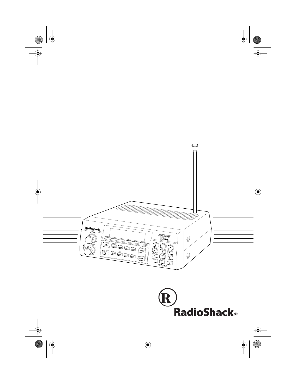
Owner’s Manual
300-Channel TrunkTracker Home Scanner
Please read before using this equipment.
Cat. No. 20-430
PRO-2050
VHF/UHF/Air/800MHz
Page 2

g
y
20-430 .fm Page 2 Wednesday, A ugust 4, 1999 1:29 PM
FEATURES
Your new RadioShack PRO-2050
VHF/UHF/Air/800MHz 300-Channel
TrunkTracker Home Scanner is one of
a new generation of scanners designed to track Motorola Type I,
Type II (such as Smartnet and Privacy Plus), and hybrid analog trunking
systems, which are extensively used
in many 800 MHz communication systems.
Trunking communications systems let
a large group of 2-way radio users (or
even different groups of 2-way radio
users) efficiently use a group of frequencies. Instead of selecting a specific frequency for a transmission, the
2-way radio user simply selects a talk
group. The trunking system automatically transmits the call on the first
available frequency, an d also sends a
code that uniquely identifies that 2way radio user’s transmission on a different frequency called a data channel.
Since the trunking sy stem might send
individual 2-way radio user’s calls and
response transmissions on different
frequencies, it is difficult to listen to
trunked communications using a regular scanner. The PRO-2050 monitors
the data channel frequency sent with
a 2-way radio user’s transmission and
instantly switches to an active frequency, so you c an hear the call and
response for that 2-way radio user
and easily “follow” the conversation.
The scanner also lets you scan conventional transmissions, and is preprogrammed with service-search
banks for convenience. B y pressing a
single button, you can quickly search
those frequencies most commonly
used by public service and other
agencies without tedious and complicated programming.
This scanner gives you direct access
to over 30,000 exciting frequencies,
including those used by police and fire
departments, ambulance services,
and amateur radio services, and you
can change your selection at any time.
Your scanner also has these special
features:
Ten Channel-Stora
e Banks
— let
you store 30 channels in each bank to
group channels so you can more easily identify calls.
Five Scan Lists
— let you st ore u p t o
50 IDs in each tracking bank (up to a
total of 500).
Triple-Co nversion Circ uitr
— virtually eliminates any interference from
IF (intermediate frequency) images,
so you hear only the selected frequency.
©
1997 Tandy Corporation.
RadioShack i s a regist ered t rademark used by Tandy Co rporation.
HyperSearch and HyperScan are trademarks used by Tandy Corporation.
Motorola, Smartnet, and Privacy Plus are trademarks of Motorola, Inc.
All Rights Reserv ed .
2
Page 3

20-430 .fm Page 3 Wednesday, A ugust 4, 1999 1:29 PM
Scan Delay — delays scanning for
about 2 seconds before moving to another channel in conventional mode,
so you can hear more replies that are
made on the same channel. In trunk
tracking mode, it delays for about 5
seconds before moving to another ID.
Lock-Out Function — lets you set
your scanner to skip over specified
channels or frequencies when scanning or searching, and skip over IDs
when tracking trunked systems.
Priority Channels — lets you program one channel in each bank (10 in
all). As the scanner scans a bank, it
checks the bank’s priority channel every 2 seconds so you don't miss transmissions on that channel.
Five Service-Search Banks — lets
you search preset frequencies in separate public service, police, fire/emergency, aircraft, and weather banks, to
make it easy to locate specific types of
calls.
signals, making a scan or search faster.
Manual Access — lets you directly
access any stored channel.
Liquid-Crystal Display — makes it
easy to view and change programming information.
Display Backlight — makes the
scanner easy to read in low-light situations.
Supplied Telescoping Antenna —
provides good reception of strong local signals.
External Antenna Terminal — lets
you connect an external antenna with
a BNC connector to the scanner for
improved reception of distant/weaker
signals.
Memory Backup — k eeps the channel frequencies stored in memory for
an extended time.
HyperSearch and HyperScan —
let you set the scanner to search at up
to 300 steps per second (in frequ ency
bands with 5 kHz steps) and scan at
up to 50 channels per s econd, to help
you quickly find interesting broadcasts. (The normal search speed is
100 steps per second).
Data Signal Skip — lets yo u set the
scanner to skip non-modulated or data
signals during scanning and searches.
This lets the scanner avoi d non-voice
Key Confirmation Tones — the
scanner sounds a tone when you perform an operation correctly, and an error tone if you make an error.
Duplicate Channel Alert — warns
you when the frequency you are storing already exists in memory.
3
Page 4

20-430 .fm Page 4 Wednesday, A ugust 4, 1999 1:29 PM
Your PRO-2050 scanner can receive
all of these bands:
Frequency
Range
29–29.7 MHz 10-Meter Amateur
29.7–50 MHz VHF Lo
50–54 MHz 6-Meter Ham Band
108–136.975
MHz
137–144 MHz Military Land Mobile
144–148 MHz 2-Meter Ham Band
148–174 MHz VHF Hi
406–420 MHz Federal
420–450 MHz 70-cm Ham Band
450–470 MHz UHF Standard Band
470–512 MHz UHF “T” Band
806–824 MHz
851–869 MHz
896–956 MHz
T ypes of
Tr ansm issions
Radio
Aircraft
Government
Public Service “800 ”
except
Cellular Band
FCC NOTICE
Your scanner might caus e T V or radi o
interference even when it is operating
properly. To determine if your scan ner
is causing the interference, turn off
your scanner. If the interference goes
away, your scanner is causing it. Try
to eliminate the interference by:
• Moving your scanner away from
the receiver
• Connecting your scanner to an
outlet that is on a different electr ical circuit from the receiver
• Contacting your local RadioShack store for help
If you cannot eliminate the interference, the FCC requires that you stop
using your scanner.
This device complie s with Part 15 of
FCC Rules
the
the following two conditions: (1) This
device may not cause harmful interference, and (2) this device must accept
any interference received, including
interference that may cause undesired
operation.
. Operation is subject to
Note: See “Specifications” on Page 51
for more information about the scanner’s frequency steps.
4
We recommend you record your scanner’s serial number here. The number
is on the scanner’s back panel.
Serial Number _________________
Page 5

20-430 .fm Page 5 Wednesday, A ugust 4, 1999 1:29 PM
SCANNING LEGALLY
Scanning is a fun and interesting hobby. You can hear police and fire departments, ambulance services,
government agencies, private companies, amateur radio services, aircraft,
and military operations. It is legal to
listen to almost every transmission
your scanner can receive. However,
there are some electronic and wire
communications that are illegal to intentionally intercept. These include:
• Telephone conversations (cellular, cordless, or other private
means of telephone signal transmission)
• Pager transmissions
• Scrambled or encrypted transm issions
According to the Federal Electronic
Communications Privacy Ac t (ECPA),
as amended, you c ould be fined and
possibly imprisoned for intentionally
intercepting, using, or disclosing the
contents of such a transmission unless you have the consent of a party to
the communication (unless such activity is otherwise illegal). These laws
change from time to time and there
might be state or lo cal laws that also
affect legal scanner usage.
5
Page 6

g
20-430 .fm Page 6 Wednesday, A ugust 4, 1999 1:29 PM
CONTENTS
Preparation ........................................................................................................... 8
Connecting an Antenna ................................................................................... 8
Connecting the Supplied Antenna ............................................................... 8
Connecting an Outdoor Antenna ................................................................. 8
Connecting Power ........................................................................................... 9
Using AC Power .......................................................................................... 9
Using Your Vehicle’s Battery Power .......................................................... 10
Connecting an Extension Speaker ................................................................ 10
Connecting an Earphone/Headphones ......................................................... 11
Listening Safely ......................................................................................... 11
Understandin
A Look at the Front Panel .............................................................................. 12
A Look at the Display ..................................................................................... 14
Understanding Banks ............................................................. ....... .. .......... .... 16
Channel Storage Banks . ............................................................................ 16
Service Banks ............................................................................................ 16
Understanding Trunking ........................................................... ....... ..... ....... .. 16
Operation ............................................................................................................ 17
Turning On the Scanner and Setting Squelch ............................................... 17
Storing Known Frequencies into Channels ................................................... 17
Searching Service Banks .............................................................................. 18
Limit Search ................................................................................................... 19
Scanning the Stored Channels ...................................................................... 20
Manually Selecting a Channel ....................................................................... 20
Clearing a Frequency from a Channel ........................................................... 21
Special Features ............................................................................................... 22
Delay ............................................................................................................. 22
Turning Channel-Storage Banks On and Off . ................................................ 22
Locking Out Channels and Frequencies ....................................................... 23
Locking Out Channels ............................................................................... 23
Locking Out Frequencies ........................................................................... 23
Priority ........................................................................................................... 24
Turning the Key Tone On/Off . . ....................................................................... 25
Changing Search Speeds .............................................................................. 25
Skipping Data Signals ................................................................................... 25
Your Scanner ............................................................................ 12
6
Page 7

20-430 .fm Page 7 Wednesday, A ugust 4, 1999 1:29 PM
Trunk Tracking ................................................................................................... 26
Types of Trunking Systems ........................................................................... 26
Setting the Scanner to the Trunk Tracking Mode .......................................... 27
Setting Squelch for the Trunk Tracking Mode ............................................... 27
Programming Trunked Frequencies .... .......................................................... 28
Scanning a Trunked Bank ............................................................................. 29
Monitoring an Active ID ............................................................................. 30
Locking Out IDs ......................................................................................... 30
Unlocking a Single ID ................................................................................ 31
Unlocking All IDs ....................................................................................... 31
Using Trunk Tracking Scan Delay ............................................................. 31
Monitoring IDs ........................................................................................... 32
Channel Activity Indicators . ........................................................................... 32
Scan Lists ..................................................................................................... 33
Manually Storing IDs into Scan Lists ......................................................... 33
Storing IDs Into Scan Lists While Searching ............................................. 34
Automatically Storing an ID in a Scan List Location .................................. 34
Deleting a Stored ID .................................................................................. 34
Scanning the Scan Lists ............................................................................... 34
Scanning Type I and Hybrid Trunked Systems ............................................. 35
Selecting a Preset Fleet Map .................................................................... 38
Programming a Fleet Map ......................................................................... 39
Programming a Hybrid System ................................................................. 40
A General Guide to Scanning ........................................................................... 41
Guide to Frequencies .................................................................................... 41
National Weather Frequencies .................................................................. 41
Canadian Weather Frequencies ............................................................... 41
Birdie Frequencies .................................................................................... 41
Guide to the Action Bands ............................................................................ 42
Typical Band Usage .................................................................................. 42
Primary Usage .......................................................................................... 43
Band Allocation ............................................................................................. 43
Frequency Conversion .................................................................................. 48
Troubleshooting ................................................................................................ 49
Resetting the Scanner .................................................................................. 52
Care and Maintenance ...................................................................................... 53
Specifications .................................................................................................... 54
7
Page 8
g
g
20-430 .fm Page 8 Wednesday, A ugust 4, 1999 1:29 PM
PREPARATION
This scanner is designed primarily for
use in the home as a base station.
You can place it on a desk, shelf, or
table.
Your scanner’s front feet fold up or
down. Adjust them to give you the
best view of the display.
Your scanner’s display is protected
during shipment by a piece of blue
film . Peel off th is film be fore you u se
the scanner.
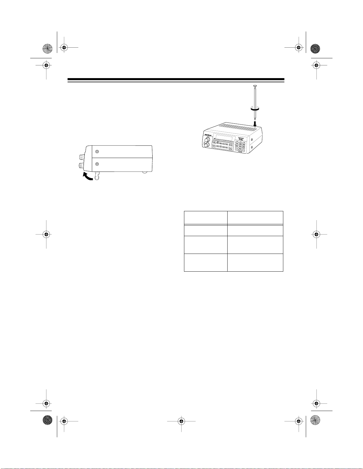
The scanner’s sens itivity depends on
the antenna’s length and vario us env ironmental conditions. For the best reception of the transmissions you want
to hear, adjust the antenna’s length.
Frequency Antenna Length
CONNECTING AN
ANTENNA
Connecting the Supplied
Antenna
You must install an antenna before
you can operate the scanner.
The supplied telescoping antenna
helps your scanner receive st rong local signals. To install the antenna,
screw it clockwise into the hole on the
scanner’s top.
8
29–54 MHz Extend fully
108–174 MHz Collapse one
se
ment
406–956 MHz Collapse both
se
ments
Connecting an Outdoor
Antenna
Instead of the supplied antenna, you
can connect an outdoor base-station
or mobile antenna (not supplied) to
your scanner using a B NC connector.
Your local RadioShack store sells a
variety of antennas. Choose the one
that best meets your needs.
When deciding on a mobile or basestation antenna and its locat ion, consider these points:
Page 9
g
20-430 .fm Page 9 Wednesday, A ugust 4, 1999 1:29 PM
• The antenna should be as high as
possible on the vehicle or building.
• The antenna and its cable should
be as far as possible from sources
of electrical noise (appliances,
other radios, etc.).
• The antenna should be vertical for
the best performance.
To connect an optional base-station or
mobile antenna, first remove the supplied antenna from the scanner. Always use 50-ohm coaxial cable, such
as RG-58 or RG-8, to connect the
base-station or mobile antenna. For
lengths over 50 feet, use RG-8 lowloss dielectric coaxial cab le. If the antenna cable’s connector does not fit in
ANT.
the
jack, you might also need a
Motorola-to-BNC antenna plug a dapter, such as RadioShack Cat. No. 278-
117. Your local RadioShack store carries a wide variety of coaxial antenna
cable and connectors.
Once you choose an antenna, follow
the mounting instructions supplied
with the antenna. Then rout e the antenna’s cable to the scanner and connect the cable to t he
ANT.
jack on the
back of the scanner.
Cautions:
• Do not run the cable over sharp
edges or moving parts that might
damage it.
• Do not run the cable next to power
cables or other antenna cables.
Use extreme caution
Warnin
:
when you install or remove an outdoor antenna. If the antenna starts
to fall, let it go! It could contact
overhead power lines. If the antenna touches a power line, contact
with the antenna, mast, cable, or
guy wires can cause electrocution
and death. Call the power company to remove the antenna. DO
NOT attempt to do so yourself.
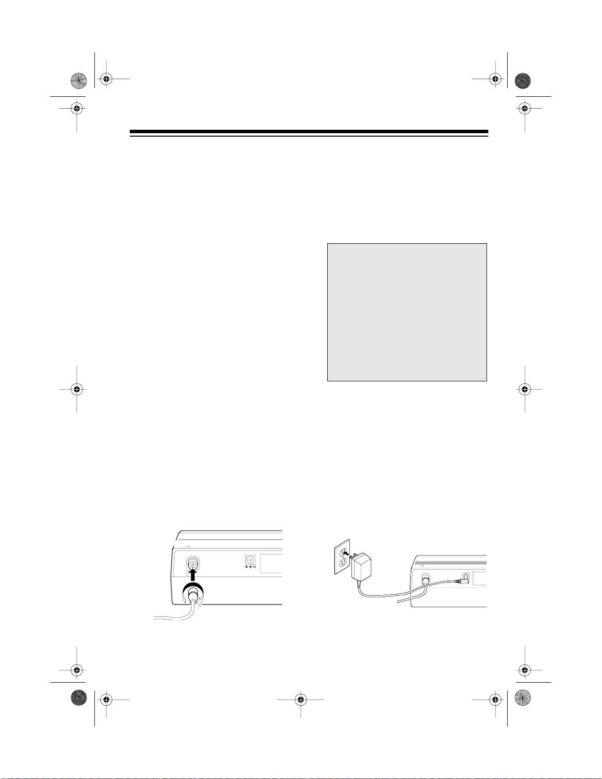
CONNECTING POWER
Using AC Power
The scanner’s supplied AC adapter
lets you power the scanner from a
standard AC outlet. To connect power
to the scanner, insert the AC adapter’s
barrel plug into the
back of the scanner, then plug the AC
adapter into a standard AC outlet.
DC 12V
jack on the
ANT
DC 12V
ANT
9
Page 10
20-430 .fm Page 10 We dnesday, A ugust 4, 1999 1:29 PM
Cautions:
• The supplied AC adapter supplies
12 volts DC power and delivers
500 milliamps. Its center tip is set
to positive, and its plug properly
fits the scanner’s
DC 12V
jack.
Using an adapter that does not
meet these specifications could
damage the scanner or the
adapter.
• Be sure to connect the AC
adapter to the scanner before you
connect it to an AC outlet, and disconnect the AC a dapter from the
AC outlet before you d isconnect it
from the scanner.
Warning: Do not use the AC adapter’s polarized plug with an extension
cord receptacle unless the blades can
be fully inserted to preven t blade exposure.
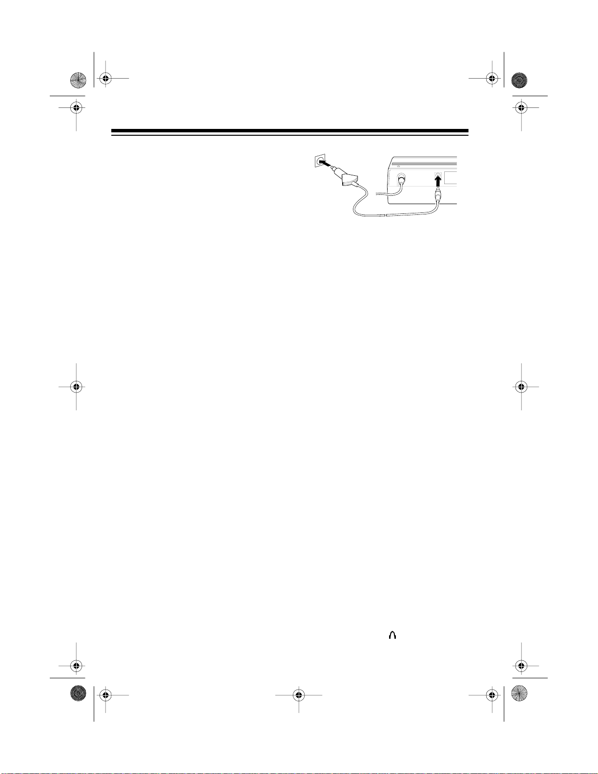
Using Your Vehicle’s Battery
Power
ANT
DC 12V
Cautions:
• If you use a DC cigarette lighter
power cable with the scanner, it
must supply 12 volts and at least
500 milliamps of DC automotive
power. Its center tip must be set to
positive, and its plug must correctly fit the
DC 12V
jack on the
back of the scanner. The recommended power cable mee ts these
specifications. Using a power
cable that does not meet these
specifications could damage the
scanner or the power cable.
• If you use a cigarette lighter power
cable and your vehicl e’s engine is
running, you might hear electrical
noise from the engine w hile s canning. This is normal.
If your AC power fails (during an
emergency, for example), you can
power your scanner from your vehicle’s cigarette lighter socket with an
optional DC cigarette lighter power cable, such as Cat. No. 270-1533 (not
supplied).
To connect an optional DC cigarette
lighter power cable, insert its barrel
plug into the
DC 12V
jack on the back
of the scanner, then plug the power
cable into your vehicle’s cigarette
lighter socket.
10
Note: Mobile use of this scanner is
unlawful or requires a perm it in some
areas. Check the laws in your area.
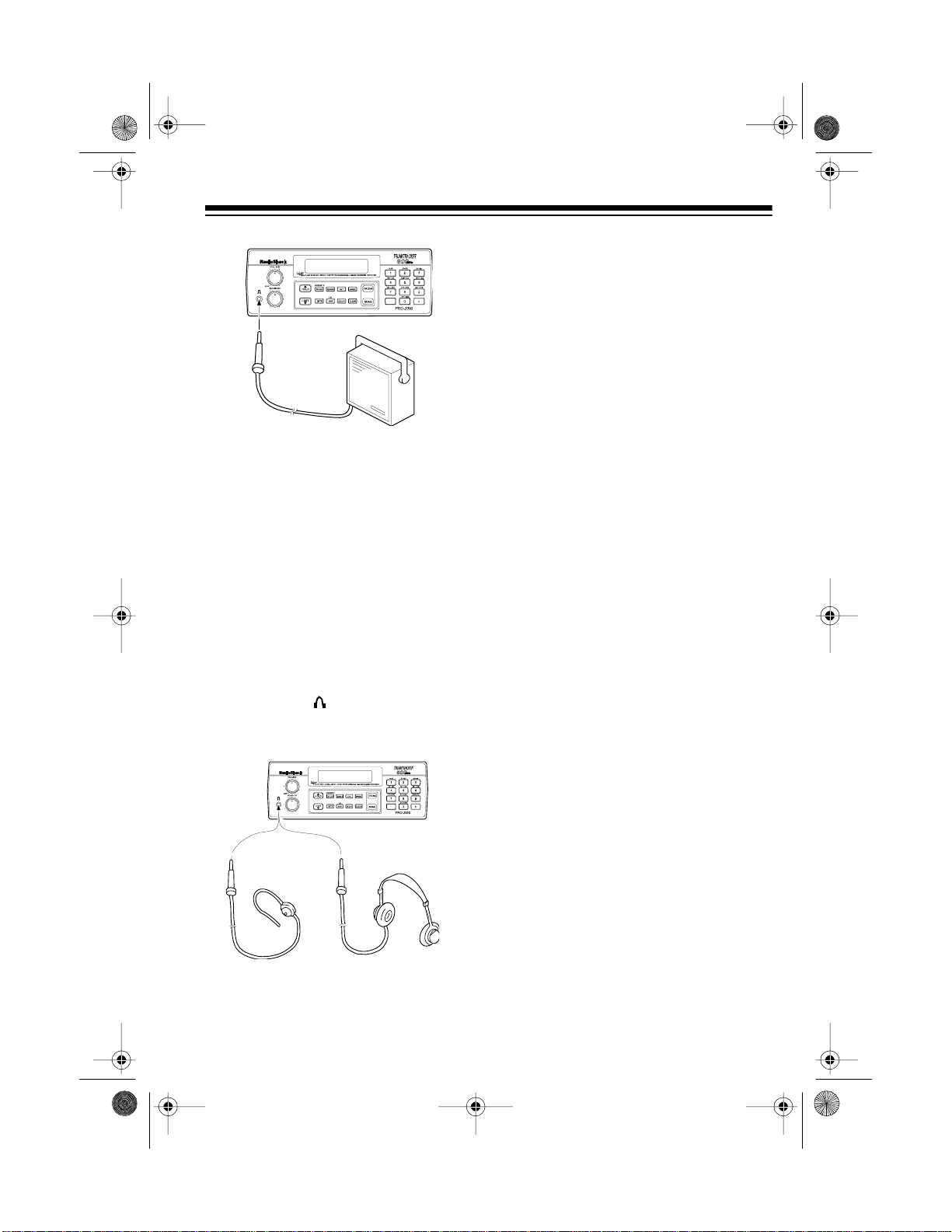
CONNECTING AN
EXTENSION SPEAKER
In a noisy area, an amplified extension
speaker (such as Cat. No. 21-541),
positioned in the right place, might
provide more comfortable listening.
Plug the speaker cable’s
into your scanner’s jack.
1
-inch plug
8
/
Page 11
20-430 .fm Page 11 We dnesday, A ugust 4, 1999 1:29 PM
Listening Safely
To protect your hearing, follow these
guidelines when you use an earpho ne
or headphones.
• Do not listen at extremely high
volume levels. Extended highvolume listening can lead to permanent hearing loss.
Note: Connecting an external speaker
disconnects the scanner’s internal
speaker.
CONNECTING AN
EARPHONE/
HEADPHONES
For private listening, you can connect
an earphone or headphones with a
inch plug (such as Cat. No. 33-175 or
20-210) to the jack on the front of
the scanner. This automatically disconnects the internal speaker.
1
/
•Set
VOLUME
to the lowest setting
before you begin listening. After
you begin listening, adjust
UME
to a comfortable level.
• Once you set
VOLUME
VOL-
, do not
increase it. Over time, your ears
adapt to the volume level, so a
volume level that does not cause
discomfort might still damage your
hearing.
-
8
11
Page 12
y
g
20-430 .fm Page 12 We dnesday, A ugust 4, 1999 1:29 PM
UNDERSTANDING YOUR SCANNER
Once you understand a few simple terms we use in this manual and familiarize
yourself with your scanner’s features, you can put the scanner to work for you. You
simply determine the type of communications you want to receive, then set the
scanner to scan them.
A
frequenc
active frequencies, you can use the
You can also search the
quencies categorized by type of service.
When you find a f requenc y, you can store it into a programmable mem ory l ocati on
called a
. You can then
bank
the frequencies stored there. Each time the s canner finds an active frequency, it
stays on that channel until the transmission ends.
is the tuning location of a station (expresse d in kHz o r MHz). To find
func ti on.
, which are preset groups of fre-
channel-stora
channel
search
service-search banks
, which is grouped with your other channels in a
the channel-storage banks to see if there is activity on
scan
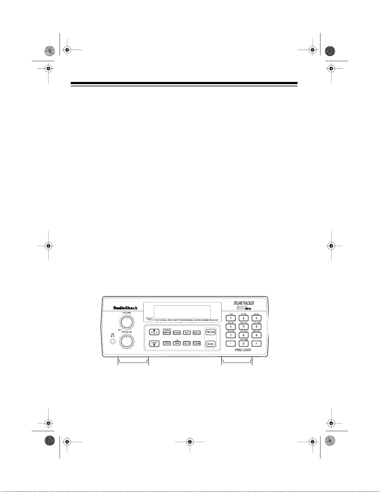
A LOOK AT THE FRONT PANEL
Your scanner’s keys migh t seem confusing at first, but this inform ati on shoul d hel p
you understand each key’s function.
Some of the scanner’s keys perform more than one function and are marked
Note:
with more than one label. The s teps in this Owner’s Manual show onl y the l abel on
the key appropriate to the action being performed.
e
VOLUME
SQUELCH
12
Turns the scanner on or off and adjusts the volume.
Adjusts the scanner’s squelch.
Page 13

20-430 .fm Page 13 We dnesday, A ugust 4, 1999 1:29 PM
SCAN
MANUAL
Scans through the stored channels.
Stops scanning and lets you directly enter a channel
number or frequency.
TRUNK
Switches between conventional and trunk tracking
modes.
SVC
(service)
PRIORITY/SPEED
Selects a service bank.
Sets and turns on and off the priority feature; turns the
HyperSearch mode on and off.
Number Keys Each key has a single-digit label and a range of num-
bers. The single digits are used to enter a channel,
frequency, or ID number. The range of numbers (31–
60, for example) indicates the channels that m ake up
a memory bank.
•
CLEAR
E
(enter)
Enters a decimal point.
Clears an entry.
Enters frequencies into channels or enters IDs into a
scan list.
LIMIT/
t Sets the frequency range; sets the search direction
and holds a frequency search.
DELAY
Programs a 2-second delay for the sele cted channel,
a limit search, or each service scan. Also programs a
5-second delay in the trunk tracking mode.
SEARCH
Searches a specified frequency range to find frequencies; searches for another active ID in the trunk tracking mode.
L/O/SKIP
(lock out/skip)
Lets you lock out selected channels or frequencies;
lets you lock out a selected ID in the trunk tracking
mode.
13
Page 14

20-430 .fm Page 14 We dnesday, A ugust 4, 1999 1:29 PM
HOLD/
s Holds on the current ID in the trunk tracking mode;
sets the search direction and holds the frequency
search.
DATA
Turns the data signal skip feature on or off or checks
the current trunking bank in the trunk tracking mode.
A LOOK AT THE DISPLAY
The display has indicators that show the scanner’s current operating status. A good
look at the display will help you understand how your scann er operates.
LIST
BANK
Appears with numbers (1–10) to indicate the scan
PUB
Appears with a number (1 –5) to indicate the list num ber.
bank.
Appears when you search the public safety service
bank.
POLICE
FIRE/EMG
AIR
WX
TRUNK
14
Appears when you search the police service bank.
Appears when you se arch the fire/emerg ency service
bank.
Appears when you search the air service bank.
Appears when you search the weather service bank.
Appears when the scanner is in trunk tracking mode.
Page 15

20-430 .fm Page 15 We dnesday, A ugust 4, 1999 1:29 PM
(channel activity indicator) active.
P
SCAN
MANUAL
PRI
HOLD
DELAY
DATA
L/O
(lockout) Appear s when you manuall y select a chan nel , frequen-
SEARCH
t
s Lights steadily during a limit search, service search,
Shows whic h cont rol/voi ce ch annel s are cu rrent ly
Appears when a priority channel is selected.
Appears when you scan channels.
Appears when you set the scanner to its manual
mode.
Appears when the priority feature is turned on.
Appears when the scanner i s in the hold mode during
a search.
Appears when you program a delay.
Appears when the data skip function is active.
cy, or ID you locked out.
and ID search, and blinks while HyperSearch is active
and when you monitor IDs. The arrow indicates the
search direction.
Error
Appears when you make an entry error.
15
Page 16

20-430 .fm Page 16 We dnesday, A ugust 4, 1999 1:29 PM
UNDERSTANDING
BANKS
Channel Storage Banks
To make it easier to identify and select
the channels you want to listen to,
channels are divided into 10 banks of
30 channels each. Use each channelstorage bank to group frequencies,
such as those used by the police department, fire department, am bulance
services, or aircraft (see “Guide to the
Action Bands” on Page 39). For example, the police department might use
four frequencies, one for each side of
town. You could program the police
frequencies starting with Channel 1
(the first channel in bank 1) and program the fire department f requencies
starting with Channel 31 (the first
channel in bank 2).
Service Banks
The scanner is preprogrammed with
the frequencies allocated by public
safety, police, fire/emergency, aircraft,
and weather services. This is handy
for quickly finding active frequencies
instead of searching through an entire
band (see “Searching Service Banks”
on Page 18).
UNDERSTANDING
TRUNKING
In the past, gro ups that broad cast frequently, such as police departments,
were restricted to transmitting on just
a few frequencies. This resulted in
heavy traffic and often required 2-way
radio users to wait for a specific frequency to clear before transmitting.
Trunked systems allow more groups
of 2-way radio users to use fewer f requencies. Instead of selecting a specific frequency to transmit on, a
trunked system chooses one of several frequencies when the 2-way radio
user presses PTT (push to talk). The
system automatically transmits the
call on that f requency, and also sends
a code that identifies that 2-way radio
user’s transmission on a data channel.
You can set this scanner to monitor
the data channel frequency, so you
can hear both the call and response
transmissions for that 2-way radio
user and therefore follow the conversation. (You cannot listen to the data
channel itself in the trunk mode.)
16
Page 17
20-430 .fm Page 17 We dnesday, A ugust 4, 1999 1:29 PM
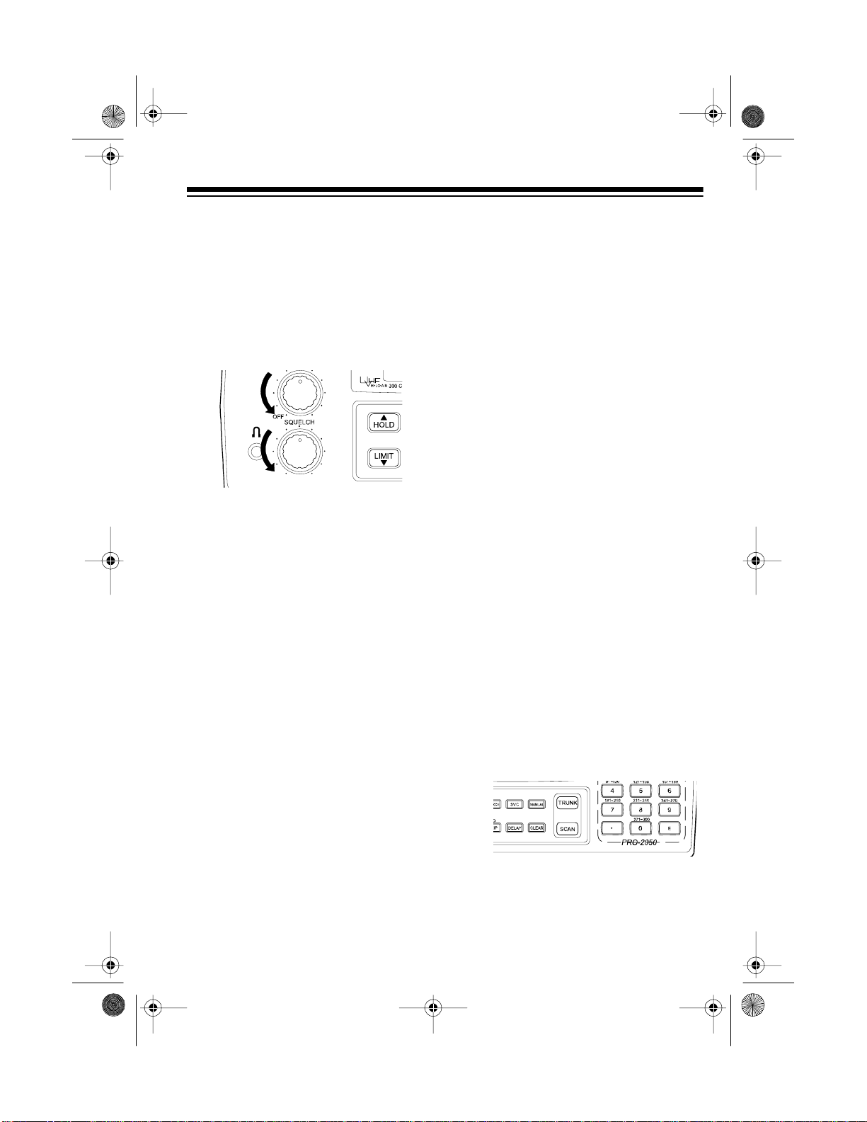
OPERATION
TURNING ON THE
SCANNER AND SETTING
SQUELCH
1. Turn
2. Turn
3. Turn
Notes:
• If the scanner will not scan, turn
• If the scanner picks up unwanted,
SQUELCH
counterclockwise.
VOLUME
you hear a hissing sound.
SQUELCH
leave it set to a p oint j us t after the
hissing sound stops.
SQUELCH
partial, or very weak transmissions, turn
decrease the scanner ’s sensitivity
to these signals. If you want to listen to a weak or distant station,
SQUELCH
turn
back clockwise un ti l
further clockwise.
SQUELCH
VOLUME
and
clockwise, then
clockwise to
counterclockwise.
fully
STORING KNOWN
FREQUENCIES INTO
CHANNELS
Good references for active frequencies are the RadioShack “Police Call
Guide including Fire and Emergency
Services,” “Official Aeronautical Frequency Directory,” and “Maritime Frequency Directory.” We update these
directories every year, so be sure to
get a current copy.
Note:
quencies, see “Programming Trunked
Frequencies” on Page 26.
Follow these steps to store frequencies into channels.
To store trunking system fre-
1. Press
nel number (1–300) where you
want to store a frequency, then
press
nel number appears.
2. Use the number keys and
enter the frequency (including the
decimal point) you want to store.
MANUAL
MANUAL
, enter the chan-
again. The chan-
•
to
SQUELCH
•If
always hear a hissing sound, the
scanner does not scan properly.
is adjusted so you
17
Page 18

20-430 .fm Page 18 We dnesday, A ugust 4, 1999 1:29 PM
3. Press E to store the frequency into
the channel.
Notes:
• If you made a mistake in Step
2, Error appears and the
scanner beeps when you press
E
. Simply start again from Step
2.
• Your scanner automatically
rounds the entered frequency to
the nearest valid frequen cy. For
example, if you enter a frequency of 151.473, your scanner accepts it as 151.475.
• If you entered a frequency that
is already stored in another
channel, the scanner beeps
three times and displays the
lowest channel number where
the frequency is already stored.
If you want to store the frequency anyway, press
E
again.
stores this setting in the channel.
4. If you want to program the next
channel in sequence, pres s
UAL
and repeat Steps 2 and 3.
MAN-
SEARCHING SERVICE
BANKS
You can search for public service, police, fire/emergency, aircraft, and
weather transmissions even if you do
not know the specific frequencies that
are used in your area. And, you can
store any of the frequencies you find
into channels.
Your scanner has the following preprogrammed service banks.
• PUBLIC — contains 140 public
service frequencies
• POLICE — contains 2,3 92 police
frequencies
• FIRE/EMG — contains 197 fire
and emergency service frequencies
• AIR — co ntains 2,319 aircraft and
air service frequencies
• WX — contains 7 weather frequencies
DELAY
•Press
scanner to pause 2 seconds on
this channel after a transmission ends before it proceeds to
the next channel (see “Delay”
on Page 21). The scanne r also
18
if you want the
To select a service bank, press
service bank’s name (
,
LICE
one of the preset public service frequencies appear. After a 2-second delay, searching begins.
FIRE/EMG, AIR
SVC
PUB, PO-
, or
WX
) and
. A
Page 19

20-430 .fm Page 19 We dnesday, A ugust 4, 1999 1:29 PM
To select another service bank, repeatedly press
SVC
until the scanner
displays the name of the bank you
want to use.
Notes:
• To skip data signals (such as
modem signals), pres s
DATA
. See
“Skipping Data Signals” on
Page 23.
• Because frequencies are not
always assigned to the same s ervices everywhere, you might hear
transmissions from one service in
another service group.
SEARCH
Press
to start searching immediately or to continue searching if
you want to skip a frequency.
During service-search, you can press
HOLD
to pause the searching.
HOLD
appears. Press s or t to move up or
down one step, or press
SEARCH
to
resume searching.
LIMIT SEARCH
If you do not know a frequency to
store, you can search for transmissions within a range of frequencies
you select, called the
range
. Then you can store a ny interesting frequencies you find into channels.
1. Press
MANUAL
nel number where you want to
store a frequency, then press
MANUAL
again. The channel num-
ber appears.
2. Use the number keys and
enter the frequency that is the
lower limit of the range you want
to search.
3. Press
LIMIT.
limit search
, enter the chan-
to
•
Follow these steps to store frequencies into channels.
1. Press
MANUAL
.
2. Use the number keys to enter the
channel number (1–300) where
you want to store the frequency,
SVC
MANUAL
SEARCH
then
.
to select a
then press
3. Press
service bank and begin searching.
4. When the scanner stops on a
HOLD
transmission, press
. The
frequency appears.
E
5. Press
to store the frequency into
the channel.
4. Use the number keys and • to
enter the frequency that is the
upper limit of the range you want
to search.
5. Press
LIMIT
, then press
SEARCH
The scanner begins to search
from the lower limit to the upper
limit.
6. When the scanner stops on a
transmission, quickly press either:
E
to store the displayed fre-
•
19
.
Page 20

20-430 .fm Page 20 We dnesday, A ugust 4, 1999 1:29 PM
quency into the channel. The
scanner stores the frequency.
• s or t to stop searching so you
can listen to the transmission.
HOLD
appears.
To release hold and continue
searching, press
Notes:
• To step through the frequencies
HOLD
while
• If you tune to a search skip frequency,
ing Out Channels and Frequencies” on Page 23.
• To skip data signals (such as
modem signals), pres s
“Skipping Data Signals” on
Page 23.
appears, press s or t.
L/O
SEARCH
appears. See “Lock-
DATA
.
. See
SCANNING THE STORED
CHANNELS
MANUALLY SELECTING
A CHANNEL
You can continuo us ly m onitor a s ingl e
channel without scanning. T his is useful if you hear an emergency broadcast on a channel and do not want to
miss any details — even t hough there
might be periods of silence — or if you
want to monitor a specific channel.
Follow these steps to manually select
a channel.
1. Press
2. Enter the channel number.
3. Press
Or, if your scanner is scanning and
stops at the desired channel, press
MANUAL
additional times causes your scanner
to step through the channels.)
To resume scanning, press
MANUAL
MANUAL
one time. (Pressing
.
again.
MANUAL
SCAN
.
To begin scanning channels, press
SCAN
. The scanner scans t hrough all
non-locked channels in all bank s that
are turned on, then stops on the first
transmission it finds. When the transmission ends, the scanner resumes
scanning.
Notes:
20
• Channels with no f requencies are
automatically locked out during
scanning.
• To scan in the trunk tracking
mode, see “Scanning a Trunked
Bank” on Page 27.
CLEARING A
FREQUENCY FROM A
CHANNEL
1. Press
2. Use the number keys to enter t he
3. Press
MANUAL
channel number containing the
frequency you want to delete.
Then press
0
, then press E. The fre-
quency is deleted.
.
MANUAL
again.
Page 21

20-430 .fm Page 21 We dnesday, A ugust 4, 1999 1:29 PM
SPECIAL FEATURES
DELAY
Many agencies use a two-way radio
system that might h ave a period of 2
or more seconds between a query and
a reply. To keep from m issing a reply,
you can program a 2-second delay
into any channel or frequency. The
scanner continues to monitor the frequency for 2 seconds after the t ransmission stops before resuming
scanning or searching.
To program a 2-second delay:
• If the scanner is scanning channel-storage banks and stops on
an active channel where you want
to store a delay, quickly press
DELAY
before scanning resumes.
DELAY
• If the desired channel is not
selected, manually select the
channel, then press
DELAY
appears.
DELAY
appears.
To turn off the 2-second delay, press
DELAY
while the scanner is monitoring
the channel or searching service
banks or limit ranges.
pears.
TUR NING CHANNELSTORAGE BANKS ON
AND OFF
You can turn each channel-storage
bank on and off. When you turn off a
bank, the scanner does not scan any
of the 30 channels in that bank.
While scanning, press the number key
that corresponds to the bank you want
to turn on or off. If the bank number is
on, the bank is turned on and the
scanner scans all channels within that
bank that are not locked out. If the
bank number is off, the scanne r does
not scan any of the channels within
that bank.
Notes:
• You can manually select any
channel within a bank, ev en i f that
bank is turned off.
.
• You cannot turn off all banks. One
bank is always active.
DELAY
disap-
• If the scanner is searching, pres s
DELAY
scanner automatically adds a 2second delay to every transmission it stops on in that band or
limit range.
DELAY
.
appears and the
21
Page 22

20-430 .fm Page 22 We dnesday, A ugust 4, 1999 1:29 PM
LOCKING OUT
CHANNELS AND
FREQUENCIES
You can scan existing channels or
search frequencies faster by locking
out channels or frequencies that have
a continuous transmission, s uch as a
weather channel.
Note:
If you just want to skip over a
lengthy transmission (such as a modem signal), see “Ski pping Data Signals” on Page 23.
Locking Out Channels
To lock out a channel while scanning,
L/O
press
the channel. To lock out a channel
manually, select the channel and
press
when the scanner stops on
L/O
until
L/O
appears.
scanning, then hold down
scanner beeps twice.
L/O
until the
Locking Out Frequencies
To lock out a freque ncy during a limit
search or service bank search, press
L/O
when the scanner stops on the
frequency. The scanner locks out the
frequency, then continues searching.
To lock out a frequency manually , select the frequency and press
L/O
appears.
Notes:
• The scanner does not display
locked-out frequencies during a
search.
L/O
appears when you select a
•
locked-out frequency.
• You can lock out up to 50 frequencies during a limit search and 20
during a service bank search. If
you try to lock out more frequencies, the first locked-out frequency
is automatically unlocked.
L/O
until
Note:
You can still manually select
locked-out channels.
To remove the lockout from a channel,
select the channel and press
L/O
disappears.
To remove the lockout from all channels in the channel-storage banks that
are turned on, press
22
MANUAL
L/O
until
to stop
To remove the lockout from a frequency, select the frequency then
L/O
press
To remove the lockout from all fre-
quencies, while searching, press
HOLD
scanner beeps twice (about 2 seconds).
L/O
.
disappears.
then hold down
L/O
until the
Page 23

20-430 .fm Page 23 We dnesday, A ugust 4, 1999 1:29 PM
TURNING THE KEY TONE
ON AND OFF
To turn the key tone off, turn off the
scanner. Then, while holding down
L/O/SKIP
bEEP
To turn the key tone back on, repeat
the above procedure.
pears.
, turn on the scanner.
appears.
oN bEEP
OF
ap-
CHANGING SEARCH
SPEEDS
The PRO-2050 has two search
speeds for a limit search.
Normal Search HyperSearch
100 steps/second 300 steps/second
To switch between the normal and HyperSearch speeds, during a limit
search, press
es during HyperSearch.
SPEED
SEARCH
.
flash-
SKIPPING DATA
SIGNALS
You can set the scanner so it skips
nonmodulated or data signals (such
as modem transmissions) during a
scan or search.
Note: Since data signals are not generally found in the air b and, this feature does not work in the air service
bank.
To turn on the data skip feature, be
sure the priority feature is turned off
(see “Priority” on Page 24), then press
DA TA
feature, press
appears.
DATA
.
appears. To turn off the
DATA
again.
DATA
dis-
TRUNK TRACKING
Your scanner is designed to track
transmissions on Motorola Type I,
Type II, and hybrid analog trunking
systems, which are extensively used
in 800 MHz communications. Remember these important points when tracking transmissions:
Note:
You can use HyperSearch only
in the 5 kHz step bands (29–54 MHz
and 137–174 MHz).
• Your scanner monitors Type II
systems by default. However, you
can change this if the system in
your area is different (see “Types
of Trunking Systems” on this page
and “Scanning Type I and Hybrid
Trunked Systems” on Page 33 for
more information).
23
Page 24

20-430 .fm Page 24 We dnesday, A ugust 4, 1999 1:29 PM
PRIORITY
The priority feature lets you scan
through channels and still not miss important or interesting calls on specific
channels. You can program one
stored channel in each bank as a priority channel (for up to a total of 10
stored channels). As the scanner
scans the bank, if the priority feature is
turned on, the scanner checks the priority channel for activity every 2 seconds.
The scanner automatically designates each bank's first channel as it s
priority channel. Follow these steps to
select a different channel as the priority channel for a bank.
1. Press
2. Enter the channel number you
MANUAL
want to select as the priority channel, then press
.
MANUAL
again.
To turn on the priority feature, press
PRIORITY
pears. As you scan the bank, the
scanner checks the bank’s priority
channel every 2 seconds in each bank
that is turned on, starting from the lowest to the highest-numbered priority
channel.
To turn off the priority feature, press
PRIORITY
Notes:
• The priority feature must be
• You can lock out priority channels.
during scanning.
PRI
.
disappears.
turned off to use the data skip feature (see “Skipping Data Sig nals”
on Page 23).
If you lock out all priority channels,
CH Loc Out
P
you turn on the priority feature.
appears when
PRI
ap-
3. Hold down
scanner beeps twice.
to the right of the channel number.
4. Repeat Steps 2–3 for the channel
in each bank you want to p rogram
as a priority channel.
24
PRIORITY
until the
appears
P
• Your scanner cannot track transmissions on non-Mot orola trunking
systems.
• Your scanner tracks an 800 MHz
trunked system
cies in conventional mode, but it
cannot do both at the same time.
• The frequencies for many of the
800 MHz public safety system s are
listed in the separate “National
Public Safety Trunked Sys tem F requency Guide” included with your
PRO-2050.
or
scans frequen-
Page 25

20-430 .fm Page 25 We dnesday, A ugust 4, 1999 1:29 PM
TYPES OF TRUNKING
SYSTEMS
Your trunk tracking scanner can moni tor two basic types of systems —
I
Type II
and
specific frequency to transmit on, a
trunked system chooses one of sev eral frequencies in a 2-way radio user’s
talk group when that user presses
PTT (push to talk). Thus, trunking systems allocate a few frequencies
among many different users, but the
way Type I and Type II systems do
this is slightly d ifferent. O ne import ant
distinction between these systems is
the amount of data transmitted by
each radio when its PTT button is
pressed. In a Type I system, the radio’s ID and its current affiliation (the
trunk system it belongs to) are both
transmitted. In a Type II system, only
the radio’s ID is transmitted.
Why the difference? In Type I systems, each radio in the trunk group i ndividually transmits its own affiliation,
while the trunk system maintains a database that determines each radio's
affiliati o n (s) in Type II systems.
Another difference between the systems is that Type I systems are arranged in a fleet-subfleet hierarchy.
For example, it is possible for a city
using a Type I system to designate 4
fleets, each with 8 subfleets.
The fleets migh t be the po lice department, the fire department, utilities, and
city administration. The police might
decide to further divide its fleet into
. Instead of selecting a
Type
subfleets such as dispatch, tactical
operations, detectives, north, south,
east and west side patrols, and supervisors. All the available police radios
would then be assigned to one of the
police subfleets, letting the police c entralize their communications and control the type of users on a single
system. Determining the exact fleetsubfleet hierarchy for a part icular area
is referred to as
ming
.
The disadvantage of a Type I system
is that the brief burst of data sent
when a user transmits must contain
the radio’s ID and its fleet and subfleet. This is three times the amount of
data a Type II system radio sends.
Since the data capacity of Type I systems is limited and the amount of data
increases with each user, Type I systems usually accommodat e fewer users than Type II systems. Nevertheless, Type I syst ems are still i n use.
There are also
are a combination o f both Type I a nd
Type II. Your scanner defaults to monitor Type II systems, but you can
change to Type I or a hybrid of Type I
and Type II systems by selecting a
preprogrammed fleet map o r creating
a custom fleet map for your area (see
“Scanning Type I and Hy brid Trunked
Systems” on Page 33).
You do not need to determine the
fleet-subfleet hierarchy for Type II systems unless you are tracking hybrid
systems that contain both Type I and
Type II systems.
fleet map program-
hybrid
systems which
25
Page 26

20-430 .fm Page 26 We dnesday, A ugust 4, 1999 1:29 PM
SETTING THE SCANNER
TO THE TRUNK
TRACKING MODE
Note:
You can change this setting, if
necessary, to provide better performance in your area.
Press
scanner’s conventional and trunk
tracking modes.
TRUNK
to switch between the
SETTING SQUELCH FOR
THE TRUNK TRACKING
MODE
Your scanner’s squel ch setting is automatically adjusted in the trunking
mode, which means you do not need
to manually adjust squelch while
tracking trunked transmissions. However, the squelch setting can affect
how fast your scanner acquires the
data channel, and, in some instances ,
can prevent your scanner from acqu iring the data channel at all.
We recommend you set
this position before selecting a trunked
bank.
SQUELCH
to
PROGRAMMING
TRUNKED
FREQUENCIES
Before you program your scanner to
track a trunked system, consider the
following:
• Valid trunked system frequencies
range from 85 1.00 00–868 .987 5 i n
12.5 kHz steps.
• You can use any of your scanner’s
banks as either a trunk tracking
bank or conventional scanning
bank, but you cannot mix the two.
• The scanner only scans one
trunked system at a time. Although you can store frequencies
for more than one trunked s ystem
in one of your scanner’s banks,
the scanner only scans the frequencies associated with the first
data channel it finds.
Before scanning a trunked system’s
transmissions, you must store the
trunked system’s frequencies in one of
the banks in your scanner by following
these steps.
1. Hold down
beeps twice.
the bank numbers flash.
TRUNK
until the scanner
BANK, TRUNK
, and
26
Page 27

20-430 .fm Page 27 We dnesday, A ugust 4, 1999 1:29 PM
2. Select the bank you want to s tore
the trunked system’s frequencies
in by pressing a number key. The
scanner automatically selects the
first channel in the bank.
3. Use the number keys to enter the
trunked system’s frequencies,
then press
4.
Note:
E
.
If you entered an invalid frequency in Step 3, the scanner
beeps, the channel number
flashes and
this happens, press
Error
appears. If
CLEAR
to
clear the frequency, then repeat
Step 3.
6. Repeat Steps 3 and 4 until all frequencies have been entered.
SCANNING A TRUNKED
BANK
You can scan one trunked bank at a
time. Once you have stored frequencies for a trunked system in one or
more of the 10 available banks and
you are scanning non-trunked frequencies, follow these steps to begin
trunk scanning.
1. Press
all banks flash.
2. Use the number keys to enter t he
number for the trunked bank you
want to sca n, th en pre ss
to begin searching for the trunk’s
data channel (the channel that
controls the trunk).
flashes as the scanner searches
for a data channel. When the
scanner finds it, it begins trunk
tracking.
TRUNK
. The indicators for
SEARCH
SEARCH
5. Press either
MANUAL
or s to
select the next channel in the
bank.
If you entered all of the trunk’s frequencies, you should be able to
follow conversations between
broadcasters even when they
change frequencies. IDs, which
represent different service groups,
appear.
27
Page 28

20-430 .fm Page 28 We dnesday, A ugust 4, 1999 1:29 PM
Note: To see the bank currently in
use for about 5 seconds, press
DATA
while in the trunk tracking
mode.
3. To return to conventional scanning, press
TRUNK
again.
Hint: While scanning, you will not
know exactly whom the IDs are assigned to until you listen awhile or until
you locate ID lists in frequency guides
or on internet sites such as
www.trunkscanner.com
. Within a few
minutes, you can usually figure out if
what you are listening to is a police,
fire, or emergency medical 2-way radio user. Other IDs might take some
time, but determining whom each ID
represents is half the fun of trunk
tracking!
Monitoring an Active ID
When the scanner stops on a transmission, you can hold the scanner on
that tr a nsmi s sion.
the ID you want to hold.
LIST 1
appears
3. Press
HOLD
again.
HOLD
flashes
and the scanner monitors that ID.
4. When you want to stop the hold
and resume searching for a data
channel so you can continue trunk
tracking, press
SEARCH
.
Note: You can also follow t hese s t eps
to hold on an ID while scanning a scan
list. See “Scan Lists” on Page 31.
Locking Out IDs
As with conventional scanning, it is
possible to lock out unwanted traffic.
This is particularly import ant in trunked systems because signals you cannot listen to (such as water meters,
door alarms, traffic signals, and encrypted signals) are ass igned IDs just
like other users. You can have up to
100 IDs locked out at one time.
1. Press
HOLD
HOLD
.
appears and
the scanner stays on the current
ID.
2. If you want to listen to a different
ID, use the number keys to ent er
28
Note: If you lock out an ID while
searching, it is also locked out of the
scan list(s). See “Scan Lists” on
Page 31.
Page 29

20-430 .fm Page 29 We dnesday, A ugust 4, 1999 1:29 PM
To lock out an ID, press
L/O
when the
ID appears.
The ID is locked out, and the next active ID appears.
Unlocking a Single ID
1. Hold down
short beeps.
2. Repeatedly press t or s to select
the I D you w ant to unlock.
3. Press
The ID is unlocked and the next
locked ID appears.
4. Press
scanner’s previous function.
L/O
L/O
.
SEARCH
until you hear two
to continue the
Using Trunk Tracking Scan
Delay
Many trunked systems have a period
of 2 or more seconds between a query
and a reply. You can program a 5second delay s o th e sc ann er holds on
an ID for 5 seconds to wait for a reply.
The scanner continues to monitor the
frequency for 5 seconds after the
transmission stops before resuming
scanning.
Press
scan delay on or off.
when trunk tracking scan delay is set.
DELAY
to turn trunk tracking
DELAY
appears
Unlocking All IDs
Hold down
beeps. Then press
IDs at once.- The scanner beeps
twice.
Note:
the scan list mode appears. Press
SCAN
scan lists or press
ue the scanner’s previous function.
For more information about scan lists,
see “Scan Lists” on Page 31.
L/O
until you hear two short
E
to unlock all the
When you unlock all the IDs,
to scan the IDs stored in your
SEARCH
to co ntin-
If you consistently miss re-
Note:
sponses even with trunk tracki ng sc an
delay set, you might need to change
the default system type or the fleet
map you are using. See “Scanning
Type I and Hybrid Trunked Sys tems”
on Page 33.
29
Page 30

20-430 .fm Page 30 We dnesday, A ugust 4, 1999 1:29 PM
Monitoring IDs
You can use your sc anne r’s display to
monitor the frequencies in a trunked
system for activity. You cannot hear
conversations in this mode, but this is
an excellent way to determine which
talk groups are the most active. To set
the scanner to monitor IDs, hold down
SEARCH
twice.
talk group IDs appear in succession.
To stop monitoring IDs, press
SEARCH
until the scanner beeps
SEARCH
again.
flashes, and all ac tive
Each frequency you store in a trunking
bank has a corresponding activity indicator.
• The indicator that remains on
steadily even when there are no
current transmissions represents
the frequency being used as the
data channel.
When you m onitor IDs, locked-
Note:
out IDs also appear.
CHANNEL ACTIVITY
INDICATORS
Your scanner has 30 channel activity
indicators (bars) which show the activity taking place on a trunked system.
You can see how many frequencies
are being used and g enerally monitor
how much communication traffic is occurring.
• The indicator that flashes when an
ID appears represents the frequency being used by the radio
you are currently hearing.
• If an indicator turns on but you do
not hear a conversation, the channel is probably being used for a
telephone interconnect call or a
private call, or the indicator might
be a locked-out ID. Your scanner
does not monitor these types of
calls.
• If the scanner is holding on an ID
which is not active, the other activity indicators turn on and off as
other groups use the system.
30
Page 31

20-430 .fm Page 31 We dnesday, A ugust 4, 1999 1:29 PM
SCAN LISTS
When you program trunked frequencies into a bank (see “Programming
Trunked Frequencies” on Page 26),
your scanner sets up 5 scan lists into
which you can store your favorite IDs .
Each list can contain up t o 10 IDs, so
you can store a total of 50 IDs for each
trunk tracking bank (500 IDs if you use
all banks as trunking banks!).
Scan lists help you organize trunk ing
system users into categories. For ex ample, you might use List 1 for police
IDs, List 2 for fire department IDs, List
3 for emergency medical service IDs,
and so on. Once IDs are stored in
lists, you can scan them like you scan
conventional channels. You can program IDs into scan lists manually, during a search, or automatically.
Manually Storing IDs into
Scan Lists
1. Select the trunking bank you want
(see “Scanning a Trunked Bank”
on Page 27).
2. After the scanner begins trunk
tracking, press
list number appears at the top of
the display, and a bar shows the
channel activity.
MANUAL
. A scan
Scan List Number
3. Repeatedly press s or t to select
the scan list location (shown at the
top of the display) you want to
program.
4. Enter the Type II ID you want to
store, then press
Or, to enter a Type I ID:
a. Use the number keys to enter
the block number and the fleet
number, then press
b. Enter the subfleet num ber, then
E
press
Note:
entering an ID, press
start over at Step 4.
5. Repeatedly press
select the next scan list location
you want to program. Then repeat
Step 4 to enter another ID.
.
To clear a mistake while
E
.
.
•
CLEAR
MANUAL
, then
or s to
31
Page 32

20-430 .fm Page 32 We dnesday, A ugust 4, 1999 1:29 PM
Storing IDs into Scan Lists
While Searching
Follow these steps to select a scan list
location and store an ID during a
search.
1. When your scanner stops on an
ID you want to store, press
ORITY
. The currently selected
scan list memory location flashes.
E
2. Press
selected scan list memory location. Or, repeatedly press s or t to
select the scan list memory location you want, then press
3. Press
ing.
to store the ID in the
SEARCH
to resume search-
PRI-
E
.
Automatically Stor ing an ID in
a Scan List Location
To display a scan list location and
store an ID in that location during a
search, press
current scan list location, then pre ss
when your scanner stops on an ID you
want to store.
To store an ID in the first available
scan list location during a search,
E
press
at any time.
PRIORITY
to display the
Deleting a Stored ID
1. Press
2. Repeatedly press s or t to select
3. Press
E
MANUAL
the scan list location (shown at the
top of the display) you want to
delete.
0
then E.
.
Scan List Location
SCANNING THE SCAN
LISTS
Press
lists you have programmed.
scrolls on the display.
SCAN
to begin scanning the
SCAN
32
If you haven’t programmed any
Note:
SCAN
IDs,
your scanner does not s top on an active conversati o n.
scrolls on the display but
Page 33

20-430 .fm Page 33 We dnesday, A ugust 4, 1999 1:29 PM
To remove a scan list from active
scanning, use the n umber key s to e nter the scan list’s number. The scan
list indicator turns off, and the IDs in
that list are not scanned.
Note: You cannot rem ov e a ll the scan
lists. One scan list must always be active.
To restore a scan list to ac tive scanning, use the number key s to enter its
number again.
SEARCH
Press
ner’s previous function.
to return to the scan-
SCANNING TYPE I AND
HYBRID TRUNKED
SYSTEMS
Your PRO-2050 is set to scan Type II
user IDs by default. When you scan
trunked frequencies, each Type II user
ID you see appears as an even number without a dash (such as 2160).
Your PRO-2050 can al so scan Type I
trunked systems. Each Type I ID appears as a three- or four-dig it num ber,
followed by a hyphen, followed by a
one- or two-digit number (such as
200-14).
If you notice a mix of odd- and evenuser IDs (such as 64 77, 2160, 6481,
6144, and 1167), then you are probably monitoring either a Type I or hybrid
(a combination of Type I and Type 2
user IDs) system. (See “Types of
Trunking Systems” on Page 25.)
You might also notice that you are
missing responses when you hold on
an active ID. Unlike Type II systems,
Type I and hybrid systems require a
fleet map that sets specific fleet-subfleet parameters. It is easy to select a
fleet map to sc an; what is not always
easy is selecting or programming a
map that is being used in your particular area.
When a Type I system is designed,
the address information for all its us er
IDs is divided into 8 equal-size blocks,
numbered 0–7, a nd each block is assigned a size code. When you set up
your scanner to track a Type I syst em,
you must cho ose a size code for each
block. When you have chosen a size
code for all 8 blocks, you will ha ve duplicated the
you are tracking. If you have chosen
correctly, you will be able to track
transmissi ons in that system.
Each size code defines th e number of
fleets, subfleets, and IDs each block
has. For example, you can see in the
following table that a size code of S4
has one fleet, which is divided into 16
separate subfleets, and it has a total
of 512 individual IDs.
Size Fleets Sub-
S0 Reserved block for Type II IDs
S1 128 4 16 1
fleet map
fleets
for the system
IDs Block
Used
33
Page 34

20-430 .fm Page 34 We dnesday, A ugust 4, 1999 1:29 PM
S2 16 8 64 1
S3 8 8 128 1
www.trunkscanner.com
Note:
plans to
make preset fleet maps available as
they become known.
S4 1 16 512 1
S5 64 4 32 1
S6 32 8 32 1
S7 32 4 64 1
S8 16 4 128 1
S9 8 4 256 1
S10 4 8 256 1
S11 2 16 256 1
S12 1 16 1024 2
S13 1 16 2048 4
S14 1 16 4096 8
Each ID in the block is unique. The
left-most digit is the block number in
the ID. The next two digits identify
which fleet is active, and the last digit(s) (after the hyphen) identifies the
subfleet.
The size codes s elected by a Type I
system designer depend on the specific needs of the system’s users.
Some organizations might wa nt many
subfleets with only a few radio s each,
while another organization mig ht want
only a few subfleets, with m any radios
each. To scan Type I systems, you
must select or program a fleet map
with the same size code assignments
as the trunked system. If you do this
accurately, you will track all the fleet
and subfleet combinations used by the
system. I n other words, you w ill hear
complete communicat ions whi le m oni toring a trunked system.
If you do not already know the size
codes used, you will have to guess
them. But since you do not have to figure out all the blocks at once, this is
not as hard as it seems. Select a size
code for a block, then press
SEARCH
Now listen to the communications. If
you decide you are rec eiving most of
the replies to the conversations with
IDs assigned to the block you just programmed, then you hav e probabl y selected the right size code and can
work on the next block of the map.
There are 16 preset fleet maps to
choose from, and it is best to start with
these when setting up a T ype I or hybrid trunk tracking bank. If none of the
following preset fleet maps allow you
to follow complete conversations, then
you probably need to program your
own fleet map (see “Programming a
Fleet Map” on Page 36)
E1P1 E1P2
Block Size
Code
0S110S4
1S111S4
2S112S4
3S113S4
4S114S4
5S115S4
6S116S4
7S117S4
Block Size
Code
.
34
E1P3 E1P4
Page 35

20-430 .fm Page 35 We dnesday, A ugust 4, 1999 1:29 PM
Block Size
0S40S12
1S41
2S42S4
3S43S4
4S44S4
5S45S4
6S126S4
7
Block Size
0S40S3
1S41S10
2S122S4
3
4 S4 4 S12
Code
—
E1P5 E1P6
Code
—
Block Size
Code
—
7S4
Block Size
Code
3S4
6S46S4
7S47S4
E1P9 E1P10
Block Size
Code
0S40S0
1S41S0
2S02S0
3S03S0
Block Size
Code
4S04S0
5S05S0
6S06S4
7S07S4
Block Size
Code
Block Size
Code
5S45
6S46S12
7S47
E1P7 E1P8
Block Size
Code
0S100S1
1S101S1
2S112S2
3S43S2
4S44S3
5S45S3
Block Size
—
—
Code
E1P11 E1P12
Block Size
Code
0S40S0
1S01S0
2S02S0
3S03S0
4S04S0
5S05S0
6S06S0
7S07S4
E1P13 E1P14
Block Size
Code
35
Page 36

20-430 .fm Page 36 We dnesday, A ugust 4, 1999 1:29 PM
Block Size
Code
0S30S4
1S31S3
2S112S10
3S43S4
4S44S4
5S05S4
6S06S12
7S07
E1P15 E1P16
Block Size
Code
0S40S3
1S41S10
2S42S10
3S113S11
4S114S0
5S05S0
6S126S12
Block Size
Code
—
Block Size
Code
DA TA
3. Press
.
4. Repeatedly press s or t to select
E1
(Type I and hybrid), then press
DA TA
again.
To select Type II, press
Note:
when E2 appears.
5. Repeatedly press s or t to select
the name of the map you want
E1P7
(such as
), then press E.
The scanner then searche s for transmissions using the preset map you
chose.
When the sc anner searc hes for
Note:
transmissions, you see Type I fleet
and subfleet IDs such as
100-9, 000-12
, or
400-8
100-12
.
E
,
7
—
7
—
Selecting a Preset Fleet Map
1. Press
TRUNK
twice.
bank numbers flash.
2. Select the bank where you want to
store the preset fleet map by
pressing a number key.
36
SCAN
, then hold down
until the scanner beeps
BANK, TRUNK
and the
How do you know if the preset map
you selected is correct? Listen t o see
if you are following com plete conversations. If not, try another preset map.
Programming a Fleet Map
DATA
TRUNK
.
until the scan-
BANK, TRUNK
E1
DA TA
.
1. Hold down
ner beeps twice.
and the bank number flash.
2. Select the bank where you want to
program the fleet map by pressing
a number key.
3. Press
4. Repeatedly press s or t until
appears, then press
Page 37

20-430 .fm Page 37 We dnesday, A ugust 4, 1999 1:29 PM
5. Repeatedly press s or t until
appears.
6. Press
7. Repeatedly press s or t to select
8. Repeat Step 7 until you have
9. Press
Note:
S13, or S14, these restrictions apply:
DATA
.
the size code for the first block,
E
then press
block appears.
selected a size code for each
block you want to work with.
SEARCH
the trunking programming mode,
tunes the data channel, then
begins to search using the map
you programmed.
If you select size code S12,
. The next available
. The scanner exits
USr
would not see another prompt because it uses all available blocks.
PROGRAMMING A
HYBRID SYSTEM
A hybrid system is simply a Type I
system with some of its blocks designated as Type II blocks. To program a
hybrid system, follow the steps listed
in “Programming a Fleet Map.” However, if you want a block to be T ype I I,
select size code
S0
in Step 7.
• S12 can only be assigned to
Blocks 0, 2, 4, or 6.
• S13 can only be assigned to
Blocks 0 and 4.
• S14 can only be assigned to Block
0.
Since these size codes require multiple blocks, you will be prompted for
the next available block when programming a fleet map. For example, if
you assign Block 0 as an S12, the
scanner prompts you for
block available, instead of
you assign Block 0 as an S14, you
b2
, the next
b1
. And if
37
Page 38

20-430 .fm Page 38 We dnesday, A ugust 4, 1999 1:29 PM
A GENERAL GUIDE TO SCANNING
Reception of the frequencies covered
by your scanner is mainly “line-ofsight.” That means you usually cannot
hear stations that are beyond the horizon.
GUIDE TO
FREQUENCIES
National Weather
Frequencies
162.400 162.475 162.525 162.425
162.500 162.550 162.450
Canadian Weather Frequencies
161.650 161.775 163.275
Note:
These three frequencies are not
pre-programmed in the weather service bank but can be manually programmed into a channel.
Birdie Frequencies
Every scanner has birdie frequencies.
Birdies are signals created inside the
scanner’s receiver. These operating
frequencies might interfere with
broadcasts on the s ame frequencies.
If you program one of these frequencies, you hear only noise on that frequency. If the interference is not
severe, you might be able to turn
SQUELCH
birdie. This scanner’s birdie frequencies (in MHz) are:
clockwise to cut out the
171.25 406.7625 407.8125 413.175 413.225
To find the birdies in your individual
scanner, begin by disconnecting the
antenna and movin g it away from the
scanner. Make sure that no other nearby radio or TV sets are turned on near
the scanner. Use the search function
and search every frequency range
from its lowest frequency to the highest. Occasionally, the searching will
stop as if it had found a signal, often
without any sound. That is a birdie.
Make a list of all the birdies in your
scanner for future reference.
38
Page 39

20-430 .fm Page 39 We dnesday, A ugust 4, 1999 1:29 PM
GUIDE TO THE ACTION
BANDS
Typical Band Usage
VHF Band
Low Range 29.00–50.00 MHz
6-Meter Amateur 50.00–54.00 MHz
Aircraft 108.00–136.00 MHz
U.S. Government 137.00–144.00 MHz
2-Meter Amateur 144.00–148.00 MHz
High Range 148.00–174.00 MHz
UHF Band
U.S. Government 406.00–420.00 MHz
70-cm Amateur 420.00–450.00 MHz
Low Range 450.00–470.00 MHz
FM-TV Audio Broadcast, Wide Band 470.00–512.00 MHz
Public Service 806.00–823.93 MHz
Conventional Systems 851.00–856.00 MHz
Conventional/Trunked Systems 856.00–861.00 MHz
Trunked Systems 861.00–866.00 MHz
Public Safety 866.00–868.93 MHz
High Range 896.11–902.00 MHz
33-Centimeter Amateur 902.00–928.00 MHz
Private Trunked 935.00–940.00 MHz
General Trunked 940.00–941.00 MHz
Fixed Services 941.00–944.00 MHz
Studio-to-Transmitter Broadcast Links 944.00–952.00 MHz
Private Fixed Services, Paging 952.00–960.00 MHz
Aeronautical Navigation 960.00–1000.00 MHz
39
Page 40

20-430 .fm Page 40 We dnesday, A ugust 4, 1999 1:29 PM
Primary Usage
VHF Band
As a general rule, most of the radio activity is concentrated on the following
frequencies:
Activities Frequencies
Government, Police, and Fire 153.785–155.980 MHz
Emergency Services 158.730–159.460 MHz
Railroad 160. 000–161.900 MHz
UHF Band
Activitie s Frequencies
Land-Mobile “Paired” Frequencies 450.000–470.000 MHz
Base Stations 451.025–454.950 MHz
Mobile Units 456.025–459.950 MHz
Repeater Units 460.025–464.975 MHz
Control Stations 465.025–469.975 MHz
Remote control stations and mo-
Note:
AbbreviationsServices
bile units operate at 5 MHz higher than
their associated base stations and relay repeater units.
BAND ALLOCATION
BIFCBoise (ID) Interagency Fire Cache
BUSBusiness
CAPCivil Air Patrol
CBCitizens Band
CCACommon Carrier
CSBConventional Systems
CTSBConventional /Trunked Systems
To help decide which frequency ranges to scan, use the following listing of
the typical services that use the frequencies your scanner receives.
These frequencies are subject to
change, and might vary from area to
area. For a more c omplete listing, refer to the “Police Call Radio Gu ide including Fire and Emergency
Services,” available at your local RadioShack store.
40
Page 41

g
g
g
20-430 .fm Page 41 We dnesday, A ugust 4, 1999 1:29 PM
FIRE . . . . . . . . . . . . . . . . . . . . . . . . . . . . . . . . . . . . . . . . . . . . . . . . . . . . . . . Fire Department
HAM . . . . . . . . . . . . . . . . . . . . . . . . . . . . . . . . . . . . . . . . . . . . . . . . . . . Amateur (Ham) Radio
GOVT . . . . . . . . . . . . . . . . . . . . . . . . . . . . . . . . . . . . . . . . . . . . . . . . . . . Federal Government
GMR . . . . . . . . . . . . . . . . . . . . . . . . . . . . . . . . . . . . . . . . . . . . . . . . . . . General Mobile Radio
GTR . . . . . . . . . . . . . . . . . . . . . . . . . . . . . . . . . . . . . . . . . . . . . . . . . . . . . . . General Trunked
IND . . . . . . . . . . . . . . . . . . . . . . . . . . . . . . . . . . . . . . . . . . . . . . . . . . . . . . .Industrial Services
. . . . . . . . . . . . . . . . . . . . . . . . (Manufacturin
MAR . . . . . . . . . . . . . . . . . . . . . . . . . . . . . . . . . . . . . . . . . . . . . . . . . . Military Amateur Radio
MARI . . . . . . . . . . . . . . . . . . . . . . . . . . . . . . . . . . . . . . . . . . . . . . . . . . Maritime Limited Coast
. . . . . . . . . . . . . . . . . . . . . . . . . . . . . . . . . . . . . . . . . . (Coast Guard, Ma ri ne Telephone,
. . . . . . . . . . . . . . . . . . . . . . . . . . . . . . . . . . . . . . . . . .Shipboard Radio, Private Stations)
MARS . . . . . . . . . . . . . . . . . . . . . . . . . . . . . . . . . . . . . . . . . . . .Military Affiliate Radio System
MED . . . . . . . . . . . . . . . . . . . . . . . . . . . . . . . . . . . . . . . . . . . . . Emer
MIL . . . . . . . . . . . . . . . . . . . . . . . . . . . . . . . . . . . . . . . . . . . . . . . . . . . . . . . . . . . .U.S. Military
MOV . . . . . . . . . . . . . . . . . . . . . . . . . . . . . . . . . . . . . . . . . . . . . Motion Picture/Video Industry
NEW . . . . . . . . . . . . . . . . . . . . . . . . . . . . . . . . . . . . . . . . . . . . . . . . . . . . .New Mobile Narrow
NEWS . . . . . . . . . . . . . . . . . . . . . . . . . . . . . . . . . . . . . . .Relay Press (Newspaper Reporters)
OIL . . . . . . . . . . . . . . . . . . . . . . . . . . . . . . . . . . . . . . . . . . . . . . . . . . . .Oil/Petroleum Industry
POL. . . . . . . . . . . . . . . . . . . . . . . . . . . . . . . . . . . . . . . . . . . . . . . . . . . . . . .Police Department
PUB. . . . . . . . . . . . . . . . . . . . . . . . . . . . . . . . . . . . . . . . . . . . . . . . . . . . . . . . . Public Services
. . . . . . . . . . . . . . . . . . . . . . . (Public Safety, Local Government, Forestry Conservation)
PSB. . . . . . . . . . . . . . . . . . . . . . . . . . . . . . . . . . . . . . . . . . . . . . . . . . . . . . . . . . . Public Safety
PTR. . . . . . . . . . . . . . . . . . . . . . . . . . . . . . . . . . . . . . . . . . . . . . . . . . . . . . . . .Private Trunked
ROAD . . . . . . . . . . . . . . . . . . . . . . . . . . . . . . . . . . . . . . . . . . . Road & Hi
RTV. . . . . . . . . . . . . . . . . . . . . . . . . . . . . . . . . . . . . . . . .Radio/TV Remote Broadcast Pickup
TAXI . . . . . . . . . . . . . . . . . . . . . . . . . . . . . . . . . . . . . . . . . . . . . . . . . . . . . . . . . . Taxi Services
TELB . . . . . . . . . . . . . . . . . . . . . . . . . . . . . . . . . . . . . . . . . . . . . . . . . . . . . . Mobile Telephone
. . . . . . . . . . . . . . . . . . . . . . . . . .(Aircraft, Radio Common Carrier, Landline Companies)
TELC. . . . . . . . . . . . . . . . . . . . . . . . . . . . . . . . . . . . . . . . . . . . . . . . . . . . . . .Cordless Phones
TELM . . . . . . . . . . . . . . . . . . . . . . . . . . . . . . . . . . . . . . . . . . . . . . . . Telephone Maintenance
TOW . . . . . . . . . . . . . . . . . . . . . . . . . . . . . . . . . . . . . . . . . . . . . . . . . . . . . . . . . . . To w Trucks
TRAN . . . . . . . . . . . . . . . . . . . . . . . . . . . . . . . . . . . . . . . . . . . . . . . . Transportation Services
. . . . . . . . . . . . . . . . . . . . . . . . . . . . . . . . . .(Trucks, Tow Trucks, Buses, Rail road, Other)
TSB . . . . . . . . . . . . . . . . . . . . . . . . . . . . . . . . . . . . . . . . . . . . . . . . . . . . . . . Trunked Systems
TVn . . . . . . . . . . . . . . . . . . . . . . . . . . . . . . . . . . . . . . . . . . . . . . . . . . FM-TV Audio Broadcast
USXX . . . . . . . . . . . . . . . . . . . . . . . . . . . . . . . . . . . . . . . . . . . . . . . . . Government Classified
UTIL . . . . . . . . . . . . . . . . . . . . . . . . . . . . . . . . . . . . . . . . . . . . . . . . . . Power & Water Utilities
WTHR . . . . . . . . . . . . . . . . . . . . . . . . . . . . . . . . . . . . . . . . . . . . . . . . . . . . . . . . . . . . .Weather
, Construction, Farming, Forest Products)
ency/Medical Serv ices
hway Maintenance
HIGH FREQUENCY (HF) — (3 MHz–30 MHz)
10-Meter Amateur Band (28.0 –29.7 MHz)
29.000–29.700 . . . . . . . . . . . . . . . . . . . . . . . . . . . . . . . . . . . . . . . . . . . . . . . . . . . . . . . . HAM
VERY HIGH FREQUENCY (VHF) — (30 MHz–300 MHz)
VHF Low Band (29.7–50 M Hz— i n 5 kHz steps)
29.700–29.790 . . . . . . . . . . . . . . . . . . . . . . . . . . . . . . . . . . . . . . . . . . . . . . . . . . . . . . . . . IND
29.900–30.550 . . . . . . . . . . . . . . . . . . . . . . . . . . . . . . . . . . . . . . . . . . . . . . . . . . . .GOVT, MIL
30.580–31.980 . . . . . . . . . . . . . . . . . . . . . . . . . . . . . . . . . . . . . . . . . . . . . . . . . . . . .IND, PUB
32.000–32.990 . . . . . . . . . . . . . . . . . . . . . . . . . . . . . . . . . . . . . . . . . . . . . . . . . . . .GOVT, MIL
33.020–33.980 . . . . . . . . . . . . . . . . . . . . . . . . . . . . . . . . . . . . . . . . . . . . . . . . BUS, IND, PUB
34.010–34.990 . . . . . . . . . . . . . . . . . . . . . . . . . . . . . . . . . . . . . . . . . . . . . . . . . . . .GOVT, MIL
41
Page 42

20-430 .fm Page 42 We dnesday, A ugust 4, 1999 1:29 PM
35.020–35.980. . . . . . . . . . . . . . . . . . . . . . . . . . . . . . . . . . . . . . . . . . .BUS, PUB, IND, TELM
36.000–36.230. . . . . . . . . . . . . . . . . . . . . . . . . . . . . . . . . . . . . . . . . . . . . . . . . . . . GOVT, MIL
36.230–36.990. . . . . . . . . . . . . . . . . . . . . . . . . . . . . . . . . . . . . .Oil Spill Cleanup, GOVT, MIL
37.020–37.980. . . . . . . . . . . . . . . . . . . . . . . . . . . . . . . . . . . . . . . . . . . . . . . . . . . . . PUB, IND
38.000–39.000. . . . . . . . . . . . . . . . . . . . . . . . . . . . . . . . . . . . . . . . . . . . . . . . . . . . GOVT, MIL
39.020–39.980. . . . . . . . . . . . . . . . . . . . . . . . . . . . . . . . . . . . . . . . . . . . . . . . . . . . . . . . . PUB
40.000–42.000. . . . . . . . . . . . . . . . . . . . . . . . . . . . . . . . . . . . . . . . . . . . . . GOVT, MIL, MARI
42.020–42.940. . . . . . . . . . . . . . . . . . . . . . . . . . . . . . . . . . . . . . . . . . . . . . . . . . . . . . . . . POL
42.960–43.180. . . . . . . . . . . . . . . . . . . . . . . . . . . . . . . . . . . . . . . . . . . . . . . . . . . . . . . . . .IND
43.220–43.680. . . . . . . . . . . . . . . . . . . . . . . . . . . . . . . . . . . . . . . . . . . . . . . TELM, IND, PUB
43.700–44.600. . . . . . . . . . . . . . . . . . . . . . . . . . . . . . . . . . . . . . . . . . . . . . . . . . . . . . . . TRAN
44.620–46.580. . . . . . . . . . . . . . . . . . . . . . . . . . . . . . . . . . . . . . . . . . . . . . . . . . . . .POL, PUB
46.600–46.990. . . . . . . . . . . . . . . . . . . . . . . . . . . . . . . . . . . . . . . . . . . . . . . . . . GOVT, TELC
47.020–47.400. . . . . . . . . . . . . . . . . . . . . . . . . . . . . . . . . . . . . . . . . . . . . . . . . . . . . . . . . PUB
47.420 . . . . . . . . . . . . . . . . . . . . . . . . . . . . . . . . . . . . . . . . . . . . . . . . . . American Red Cross
47.440–49.580. . . . . . . . . . . . . . . . . . . . . . . . . . . . . . . . . . . . . . . . . . . . . . . . . . . . . IND, PUB
49.610–49.990. . . . . . . . . . . . . . . . . . . . . . . . . . . . . . . . . . . . . . . . . . . . . . . . . . . . MIL, TELC
6-Meter Amateur Band (50–54 MHz )
50.00–54.00. . . . . . . . . . . . . . . . . . . . . . . . . . . . . . . . . . . . . . . . . . . . . . . . . . . . . . . . . . .HAM
Aircraft Band (108–136 MHz)
108.000–121.490 . . . . . . . . . . . . . . . . . . . . . . . . . . . . . . . . . . . . . . . . . . . . . . . . . . . . . . . .AIR
121.500 . . . . . . . . . . . . . . . . . . . . . . . . . . . . . . . . . . . . . . . . . . . . . . . . . . . . . AIR Emergency
121.510–136.000 . . . . . . . . . . . . . . . . . . . . . . . . . . . . . . . . . . . . . . . . . . . . . . . . . . . . . . . .AIR
U.S. Government Band (137–144 MHz)
137.000–144.000 . . . . . . . . . . . . . . . . . . . . . . . . . . . . . . . . . . . . . . . . . . . . . . . . . .GOVT, MIL
2-Meter Amateur Band (144–148 MHz)
144.000–148.000 . . . . . . . . . . . . . . . . . . . . . . . . . . . . . . . . . . . . . . . . . . . . . . . . . . . . . . .HAM
VHF High Band (148–174 MHz)
148.050–150.345 . . . . . . . . . . . . . . . . . . . . . . . . . . . . . . . . . . . . . . . . . . . . . . CAP, MAR, MIL
150.775–150.790 . . . . . . . . . . . . . . . . . . . . . . . . . . . . . . . . . . . . . . . . . . . . . . . . . . . . . . .MED
150.815–150.980 . . . . . . . . . . . . . . . . . . . . . . . . . . . . . . . . . . . . . . . . TOW, Oil Spill Cleanup
150.995–151.475 . . . . . . . . . . . . . . . . . . . . . . . . . . . . . . . . . . . . . . . . . . . . . . . . . ROAD, POL
151.490–151.955 . . . . . . . . . . . . . . . . . . . . . . . . . . . . . . . . . . . . . . . . . . . . . . . . . . . IND, BUS
151.985 . . . . . . . . . . . . . . . . . . . . . . . . . . . . . . . . . . . . . . . . . . . . . . . . . . . . . . . . . . . . .TELM
152.0075 . . . . . . . . . . . . . . . . . . . . . . . . . . . . . . . . . . . . . . . . . . . . . . . . . . . . . . . . . . . . .MED
152.030–152.240 . . . . . . . . . . . . . . . . . . . . . . . . . . . . . . . . . . . . . . . . . . . . . . . . . . . . . . TELB
152.270–152.480 . . . . . . . . . . . . . . . . . . . . . . . . . . . . . . . . . . . . . . . . . . . . . . IND, TAXI, BUS
152.510–152.840 . . . . . . . . . . . . . . . . . . . . . . . . . . . . . . . . . . . . . . . . . . . . . . . . . . . . . . TELB
152.870–153.020 . . . . . . . . . . . . . . . . . . . . . . . . . . . . . . . . . . . . . . . . . . . . . . . . . . IND, MOV
153.035–153.725 . . . . . . . . . . . . . . . . . . . . . . . . . . . . . . . . . . . . . . . . . . . . . . .IND, OIL, UTIL
153.740–154.445 . . . . . . . . . . . . . . . . . . . . . . . . . . . . . . . . . . . . . . . . . . . . . . . . . .PUB, FIRE
154.490–154.570 . . . . . . . . . . . . . . . . . . . . . . . . . . . . . . . . . . . . . . . . . . . . . . . . . . . IND, BUS
154.585 . . . . . . . . . . . . . . . . . . . . . . . . . . . . . . . . . . . . . . . . . . . . . . . . . . . . .Oil Spill Cleanup
1
54.600–154.625. . . . . . . . . . . . . . . . . . . . . . . . . . . . . . . . . . . . . . . . . . . . . . . . . . . . . . . BUS
154.655–156.24 0. . . . . . . . . . . . . . . . . . . . . . . . . . . . . . . . . . . . . . . MED, ROAD, POL, PUB
156.255–157.425 . . . . . . . . . . . . . . . . . . . . . . . . . . . . . . . . . . . . . . . . . . . . . . . . . . OIL, MARI
157.450 . . . . . . . . . . . . . . . . . . . . . . . . . . . . . . . . . . . . . . . . . . . . . . . . . . . . . . . . . . . . . .MED
157.470–157.515 . . . . . . . . . . . . . . . . . . . . . . . . . . . . . . . . . . . . . . . . . . . . . . . . . . . . . . .TOW
42
Page 43

20-430 .fm Page 43 We dnesday, A ugust 4, 1999 1:29 PM
157.530–157.725 . . . . . . . . . . . . . . . . . . . . . . . . . . . . . . . . . . . . . . . . . . . . . . . . . . IND, T AXI
157.740 . . . . . . . . . . . . . . . . . . . . . . . . . . . . . . . . . . . . . . . . . . . . . . . . . . . . . . . . . . . . . . .BUS
157.770–158.100 . . . . . . . . . . . . . . . . . . . . . . . . . . . . . . . . . . . . . . . . . . . . . . . . . . . . . .TELB
158.130–158.460 . . . . . . . . . . . . . . . . . . . . . . . . . . . . . . . . . . . . BUS, IND, OIL, TELM, UTIL
158.490–158.700 . . . . . . . . . . . . . . . . . . . . . . . . . . . . . . . . . . . . . . . . . . . . . . . . . . . . . .TELB
158.730–159.465 . . . . . . . . . . . . . . . . . . . . . . . . . . . . . . . . . . . . . . . . . . . . POL, PUB, ROAD
159.480 . . . . . . . . . . . . . . . . . . . . . . . . . . . . . . . . . . . . . . . . . . . . . . . . . . . . . . . . . . . . . . . .OIL
159.495–161.565 . . . . . . . . . . . . . . . . . . . . . . . . . . . . . . . . . . . . . . . . . . . . . . . . . . . . . .TRAN
161.580–162.000 . . . . . . . . . . . . . . . . . . . . . . . . . . . . . . . . . . . . . . . . . . . . . OIL, MARI, RTV
162.0125–162.35 . . . . . . . . . . . . . . . . . . . . . . . . . . . . . . . . . . . . . . . . . . . .GOVT, MIL, USXX
162.400–162.550 . . . . . . . . . . . . . . . . . . . . . . . . . . . . . . . . . . . . . . . . . . . . . . . . . . . . . WTHR
162.5625–162.6375 . . . . . . . . . . . . . . . . . . . . . . . . . . . . . . . . . . . . . . . . . GOVT, MIL, USXX
162.6625 . . . . . . . . . . . . . . . . . . . . . . . . . . . . . . . . . . . . . . . . . . . . . . . . . . . . . . . . . . . . . MED
162.6875–163.225 . . . . . . . . . . . . . . . . . . . . . . . . . . . . . . . . . . . . . . . . . . GOVT, MIL, USXX
163.250 . . . . . . . . . . . . . . . . . . . . . . . . . . . . . . . . . . . . . . . . . . . . . . . . . . . . . . . . . . . . . . MED
163.275–166.225 . . . . . . . . . . . . . . . . . . . . . . . . . . . . . . . . . . . . . . . . . . . GOVT, MIL, USXX
166.250 . . . . . . . . . . . . . . . . . . . . . . . . . . . . . . . . . . . . . . . . . . . . . . . . . . . .GOVT, RTV, FIRE
166.275–169.400 . . . . . . . . . . . . . . . . . . . . . . . . . . . . . . . . . . . . . . . . . . . . . . . . GOVT , BIFC
169.445–169 .505 . . . . . . . . . . . . . . . . . . . . . . . . . . . . . . . . . . . . . . . .Wireless Mik es, GOVT
169.55–169.9875 . . . . . . . . . . . . . . . . . . . . . . . . . . . . . . . . . . . . . . . . . . . GOVT, MIL, USXX
170.000–170.150 . . . . . . . . . . . . . . . . . . . . . . . . . . . . . . . . . . . . . . .BIFC, GOVT, RTV, FIRE
170.175–170.225 . . . . . . . . . . . . . . . . . . . . . . . . . . . . . . . . . . . . . . . . . . . . . . . . . . . . .GOVT
170.245–170.305 . . . . . . . . . . . . . . . . . . . . . . . . . . . . . . . . . . . . . . . . . . . . . . Wireless Mikes
170.350–170.400 . . . . . . . . . . . . . . . . . . . . . . . . . . . . . . . . . . . . . . . . . . . . . . . . . GOVT, MIL
170.425–170.450 . . . . . . . . . . . . . . . . . . . . . . . . . . . . . . . . . . . . . . . . . . . . . . . . . . . . . .BIFC
170.475 . . . . . . . . . . . . . . . . . . . . . . . . . . . . . . . . . . . . . . . . . . . . . . . . . . . . . . . . . . . . . . PUB
170.4875–173.175 . . . . . . . . . . . . . . . . . . . . . . . . . . . . . . . . . . GOVT, PUB, Wireless Mikes
173.225–173.5375 . . . . . . . . . . . . . . . . . . . . . . . . . . . . . . . . . . . . . . MOV, NEWS, UTIL, MIL
173.5625–173.5875 . . . . . . . . . . . . . . . . . . . . . . . . . . . . . . . . . . . .MIL Medical/Cras h Crews
173.60–173.9875 . . . . . . . . . . . . . . . . . . . . . . . . . . . . . . . . . . . . . . . . . . . . . . . . . . . . . GOVT
ULTRA HIGH FREQUENCY (UHF) — (406 MHz–3 GHz)
U. S. Government Band (406–420 MHz)
406.125–419.975 . . . . . . . . . . . . . . . . . . . . . . . . . . . . . . . . . . . . . . . . . . . . . . . .GOVT, USXX
70-Centimeter Amateur Band (420–450 MHz)
420.000–450.000 . . . . . . . . . . . . . . . . . . . . . . . . . . . . . . . . . . . . . . . . . . . . . . . . . . . . . . HAM
Low Band (450–470 MHz)
450.050–450.925 . . . . . . . . . . . . . . . . . . . . . . . . . . . . . . . . . . . . . . . . . . . . . . . . . . . . . . .RTV
451.025–452.025 . . . . . . . . . . . . . . . . . . . . . . . . . . . . . . . . . . . . . . . . .IND, OIL, TELM, UTIL
452.0375–453.00 . . . . . . . . . . . . . . . . . . . . . . . . . . . . . . . . . .IND, T AXI, TRAN TO W, NEWS
453.0125–454.000 . . . . . . . . . . . . . . . . . . . . . . . . . . . . . . . . . . . . . . . . . . . . . . . . . .PUB, OIL
454.025–454.975 . . . . . . . . . . . . . . . . . . . . . . . . . . . . . . . . . . . . . . . . . . . . . . . . . . . . . .TELB
455.050–455.925 . . . . . . . . . . . . . . . . . . . . . . . . . . . . . . . . . . . . . . . . . . . . . . . . . . . . . . .RTV
457.525–457.600 . . . . . . . . . . . . . . . . . . . . . . . . . . . . . . . . . . . . . . . . . . . . . . . . . . . . . . .BUS
458.025–458.175 . . . . . . . . . . . . . . . . . . . . . . . . . . . . . . . . . . . . . . . . . . . . . . . . . . . . . . MED
460.0125–460.6375 . . . . . . . . . . . . . . . . . . . . . . . . . . . . . . . . . . . . . . . . . . . FIRE, POL, PUB
460.650–462.175 . . . . . . . . . . . . . . . . . . . . . . . . . . . . . . . . . . . . . . . . . . . . . . . . . . . . . . BUS
462.1875–462.450 . . . . . . . . . . . . . . . . . . . . . . . . . . . . . . . . . . . . . . . . . . . . . . . . . .BUS, IND
462.4625–462.525 . . . . . . . . . . . . . . . . . . . . . . . . . . . . . . . . . . . . . . . .IND, OIL, TELM, UTIL
462.550–462.925 . . . . . . . . . . . . . . . . . . . . . . . . . . . . . . . . . . . . . . . . . . . . . . . . . GMR, BUS
462.9375–463.1875 . . . . . . . . . . . . . . . . . . . . . . . . . . . . . . . . . . . . . . . . . . . . . . . . . . . . MED
463.200–467.925 . . . . . . . . . . . . . . . . . . . . . . . . . . . . . . . . . . . . . . . . . . . . . . . . . . . . . . .BUS
43
Page 44

20-430 .fm Page 44 We dnesday, A ugust 4, 1999 1:29 PM
FM-TV Audio Broadcast, UHF Wide Band (470–512 MHz)
(Channels 14 through 69 in 6 MHz steps)
475.750 . . . . . . . . . . . . . . . . . . . . . . . . . . . . . . . . . . . . . . . . . . . . . . . . . . . . . . . . Channel 14
481.750 . . . . . . . . . . . . . . . . . . . . . . . . . . . . . . . . . . . . . . . . . . . . . . . . . . . . . . . . Channel 15
487.750 . . . . . . . . . . . . . . . . . . . . . . . . . . . . . . . . . . . . . . . . . . . . . . . . . . . . . . . . Channel 16
... ...
51 1.750. . . . . . . . . . . . . . . . . . . . . . . . . . . . . . . . . . . . . . . . . . . . . . . . . . . . . . . . . Channel 20
Note: Some cities use the 470–512 MHz band for land/mobile service.
Conventional Systems Band – Locally Assigned
851.0125–855.9875 . . . . . . . . . . . . . . . . . . . . . . . . . . . . . . . . . . . . . . . . . . . . . . . . . . . . . CSB
Conventional/Trunked Systems Ban d – Locally Assigned
856.0125–860.9875 . . . . . . . . . . . . . . . . . . . . . . . . . . . . . . . . . . . . . . . . . . . . . . . . . . . . CTSB
Trunked Systems Band – Locally Assigned
861.0125–865.9875 . . . . . . . . . . . . . . . . . . . . . . . . . . . . . . . . . . . . . . . . . . . . . . . . . . . . . TSB
Public Safety Band – Locally Assigned
866.0125–868.9875 . . . . . . . . . . . . . . . . . . . . . . . . . . . . . . . . . . . . . . . . . . . . . . . . . . . . . PSB
33-Centimeter Amateur Band (902–928 MHz)
902.0000–928.0000 . . . . . . . . . . . . . . . . . . . . . . . . . . . . . . . . . . . . . . . . . . . . . . . . . . . . .HAM
Privat e T runk ed
935.0125–939.9875 . . . . . . . . . . . . . . . . . . . . . . . . . . . . . . . . . . . . . . . . . . . . . . . . . . . . . PTR
General Trun ked
940.0125–940.9875 . . . . . . . . . . . . . . . . . . . . . . . . . . . . . . . . . . . . . . . . . . . . . . . . . . . . . GTR
44
Page 45

20-430 .fm Page 45 We dnesday, A ugust 4, 1999 1:29 PM
FREQUENCY CONVERSION
The tuning location of a station can be e xpressed in frequency (kHz or M Hz) or in
wavelength (meters). The following information can help you make the necessary
conversions.
1 MHz (million) = 1,000 kHz (thousand )
To convert MHz to kHz, multiply the number of megahertz by 1,000:
9.62 (MHz) ¥ 1000 = 9620 kHz
To convert from kHz to MHz, divide the number of kilohertz by 1,000:
2780 (kHz) ÷ 1000 = 2.780 MHz
To convert MHz to meters, divide 300 by the number of megahertz:
300 ÷ 7.1 MHz = 42.25 meters
45
Page 46

20-430 .fm Page 46 We dnesday, A ugust 4, 1999 1:29 PM
TROUBLESHOOTING
If your scanner is not working a s it sho uld, th ese s uggest ions m ight help you eliminate the problem. If the scanne r still does not operate properly, take it to your lo cal
RadioShack store for assistance.
PROBLEM POSSIBLE CAUSE REMEDY
Scanner is on but will not
scan.
SQUELCH
adjusted.
is not correctly
Only one channel or no
channels are stored.
Scanner is totally inoper-
No power. Make sure the scanner is
ative.
The AC or DC adapter is
not connected.
The scanner must be
reset.
Poor or no reception An antenna is not con-
nected or connected
incorrectly.
Error
appears. Programming error. Reprogram the fre-
Adjust
SQUELCH
clock-
wise.
Store frequencies into
more than one channel.
plugged into a working
AC or DC outlet.
Be sure the adapter’s
barrel plug is fully
inserted into the
DC 12V
jack.
Reset the scanner (see
“Resetting the Scanner”
on Page 49).
Make sure an antenna is
connected to the scanner.
quency correctly, including the decimal point.
In the scan mode, the
scanner locks on frequencies that have an
unclear transmission.
Scanner will not track a
trunked system.
46
Programmed frequencies are the same as
“birdie” frequencies.
The transmission might
not use a system that
can be tracked by your
scanner.
Avoid programming frequencies listed under
“Birdie Frequencies” on
Page 38 or only listen to
them manually.
Scan another transmission.
Page 47

20-430 .fm Page 47 We dnesday, A ugust 4, 1999 1:29 PM
PROBLEM POSSIBLE CAUSE REMEDY
Scanner will not track a
trunked system.
(continued)
PROBLEM POSSIBLE CAUSE REMEDY
Scanner will not stop
while scanning a scan
list.
Scanner will not acquire
a data channel.
The data frequency is
missing .
The system you are trying to track is a Type I
system, and the scanner
is set to scan Type II systems.
No IDs have been
stored.
The IDs you have stored
are not active.
SQUELCH
is not correctly adjusted for trunk
tracking.
The frequency used for
the data channel is missing.
Find the data frequency
(see “Programming
Trunked Frequencies” on
Page 26).
Set the scanner to
receive Type I trunked
frequencies. See “Scanning Type I and Hybrid
Trunked Systems” on
Page 33 .
Store one or more IDs
(see “Scan Lists” on
Page 31 ).
Scan another transmission.
Adjust squelch for trunk
tracking. See “Setting
Squelch for the Trunk
Tracking Mode” on
Page 26.
Add the frequency used
for the data channel to
the frequency list. (see
“Programming Trunked
Frequencies” on
Page 26).
Missing replies to conversations.
The system you are trying to track is a Type I
system, and the scanner
is set to scan Type II systems.
Set the scanner to
receive Type I trunked
frequencies. See “Scanning Type I and Hybrid
Trunked Systems” on
Page 33 .
47
Page 48

20-430 .fm Page 48 We dnesday, A ugust 4, 1999 1:29 PM
PROBLEM POSSIBLE CAUSE REMEDY
Missing replies to conversations.
(continued)
Channel activity indicators are lighting but no
sound is heard.
The selected fleet map is
incorrect.
Try another preset fleet
map or program your
own fleet map (see
“Scanning Type I and
Hybrid Trunked Systems”
on Page 33).
Not all of the trunk’s frequencies have been
Enter all of the trunk’s
frequencies.
entered.
The transmission might
be a private or tele-
Scan for another trans-
mission.
phone interconnect call.
The scanner does not
scan these types of
transmissions.
The ID is locked out. Unlock the ID (see
“Unlocking a Single ID”
on Page 29 or “Unlock-
ing All IDs” on Page 29 ).
48
Page 49

20-430 .fm Page 49 We dnesday, A ugust 4, 1999 1:29 PM
RESETTING THE SCANNER
You might need to reset the scanner if any of the following occur:
• The scanner’s display locks up.
• The scanner does not work properly after you connect power.
• The scanner is dropped or subjected to a physical or electrical shock.
Caution:
scanner. Use this procedure only when you are sure your scanner is not working
properly.
1. Turn off the scanner.
2. While you press and hold down
Note:
ing resetting.
Caution:
This procedure clears all the information you have program med into the
2
and 9, turn on the scanner.
It takes about 10 seconds until the reset is comp leted.
Do not turn off the scanner while you reset it.
CLEAr
appears dur-
49
Page 50

20-430 .fm Page 50 We dnesday, A ugust 4, 1999 1:29 PM
CARE AND MAINTENANCE
Your RadioShack PRO-2050 VHF/UHF/Air/800MHz 300-Channel TrunkTracker
Home Scanner is an example of superio r design and craftsmanship . The following
suggestions will help you care for your scanne r so you can enjoy it for years.
Keep the scanner dry. If it gets wet, wipe it dry immediately. Liquids can
contain minerals that can corrode the electronic circuits.
Handle the scanner gently and carefully. Dropping it can damage circuit boards and cases and can cause the scanner to work improperly.
Use and store the scanner only in normal temperature environments.
Temperature extremes c an shorten the life of electron ic devices and
distort or melt plastic parts.
Keep the scanner away from dust and dirt, which can cause premature
wear of parts.
Wipe the scanner with a damp cloth occasionally to keep it looking new.
Do not use harsh chemicals, cleaning solvents, or strong detergents to
clean the scanner.
Modifying or tampering with the sc anner’s internal components can caus e a malfunction and might inv alidate the s canne r’s warrant y and void your FCC authorization to operate it. If your scanner is not operating as it should, take it to your local
RadioShack store for assistance.
50
Page 51

20-430 .fm Page 51 We dnesday, A ugust 4, 1999 1:29 PM
SPECIFICATIONS
Frequency Coverage:
10 Meter Amateur Radio ............................. 29.000–29.6950 MHz (in 5 kHz steps)
VHF Lo ...................................................... 29.7000–49.9950 MHz (in 5 kHz steps)
6 Meter Amateur Radio ............................. 50.0000–54.0000 MHz (in 5 kHz steps)
Aircraft .............................................. 108.0000–136.9750 MHz (in 12.5 kHz steps)
Government ........................................... 137.0000–143.9950 MHz (in 5 kHz steps)
2 Meter Amateur Radio ........................... 144.000–147.9950 MHz (in 5 kHz steps)
VHF Hi ................................................... 148.0000–174.0000 MHz (in 5 kHz steps)
Amateur Radio/Government ............. 406.0000–41 9.98 75 MHz (in 12.5 kHz steps)
70-cm Amateur Radio ....................... 420.0000–44 9.9875 MHz (in 12.5 kHz steps)
UHF Standard ................................... 450.0000–46 9.98 75 MHz (in 12.5 kHz steps)
UHF “T” ............................................. 470.0000–512.0000 MHz (in 12.5 kHz steps)
Public Service ................................... 806.0000–823.9375 MHz (in 12.5 kHz steps)
Public Service/Trunking Repeater .... 851.0000–868.9875 MHz (in 12.5 kHz steps)
Public Service ................................... 896.1125–956.0000 MHz (in 12.5 kHz steps)
Channels of Operation ....................... Any 300 channels in any band combinations
(30 channels ¥ 10 banks), 50 search skip memories, and
20 service search skip memories
Sensitivity (S+N)/N=20 dB:
29–54 MHz .... .......................................................................................... 0.5 µV
108–136.975 MHz ................................................................................... 1.5 µV
137–174 MHz ......................................................................................... 0.5 µV
406–512 MHz ......................................................................................... 0.4 µV
806–956 MHz ......................................................................................... 1.0 µV
Search Speed:
Normal .............................................................................100 Steps/Sec (Max)
Hyper .......................................... 300 Steps/Sec (Max) (only 5 kHz step band)
Scan Speed ................................................................ 50 Channels/Sec. (Nominal)
Delay Time ............................................................................................. 2 Seconds
IF Frequencies:
1st IF .................................................. 29–174 MHz: 380.6050–380.7000 MHz
406–512 MHz: 380.6125–380 .700 MHz
806–956 MHz: 380.7000–380.7875 MHz
2nd IF ................................................................................................10.8 5 MHz
3rd IF .................................................................................................... 450 kHz
Squelch Sensitivity:
Threshold ............................................................................... Less than 0.6
mV
Tight ............................................................. VHF Lo, Hi, UHF (S + N)/N 25 dB
Aircraft (S + N)/N 15 dB
51
Page 52

20-430 .fm Page 52 We dnesday, A ugust 4, 1999 1:29 PM
Audio Power 1.1 W Maximum
Power Requirements:
AC Adapter 12 Volts DC
DC Adapter 12 Volts DC (such as
Cat. No. 270-1533)
3
1
Dimensions 2
4
/
× 8
/
16
× 7
11
16
/
Inch es
(HWD)
(70 × 205 × 195 mm)
Weight 26.5 oz. (750 g)
Specifications are typical; individual
units might vary. Specifications are
subject to change and improvement
without notice.
52
Page 53

20-430 .fm Page 53 We dnesday, A ugust 4, 1999 1:29 PM
53
Page 54

20-430 .fm Page 54 We dnesday, A ugust 4, 1999 1:29 PM
54
Page 55

20-430 .fm Page 55 We dnesday, A ugust 4, 1999 1:29 PM
55
Page 56

20-430 .fm Page 56 We dnesday, A ugust 4, 1999 1:29 PM
Limited One-Year Warranty
This product is warranted by RadioShack against manufacturing defects in material and workmanship under normal use for one (1) year from the date of purchase from RadioShack company-owned stores and authorized RadioShack franchisees and dealers. EXCEPT AS PROVIDED HEREIN, RadioShack MAKES NO EXPRESS
WARRANTIES AND ANY IMPLIED WARRANTIES, INCLUDING THOSE OF MERCHANTABILITY AND FITNESS FOR A PARTICULAR PURPOSE, ARE LIMITED IN DURATION TO THE DURATION OF THE WRITTEN
LIMITED WARRANTIES CONTAINED HEREIN. EXCEPT AS PROVIDED HEREIN, RadioShack SHALL HAVE
NO LIABILITY OR RESPONSIBILITY TO CUSTOMER OR ANY OTHER PERSON OR ENTITY WITH RESPECT TO ANY LIABILITY, LOSS OR DAMAGE CAUSED DIRECTLY OR INDIRECTLY BY USE OR PERFORMANCE OF THE PRODUCT OR ARISING OUT OF ANY BREACH O F THIS WARRANTY, INCLUDING, BUT
NOT LIMITED TO, ANY DAMAGES RESULTING FROM INCONVENIENCE, LOSS OF TIME, DATA, PROPERTY, REV ENUE, OR PROFIT OR ANY INDIRECT, SPECIA L, INCIDENTA L, OR CONSEQUENTIAL DAMAGES, EVEN IF RadioShack HAS BEEN ADVISED OF THE POSSIBILITY OF SUCH DAMAGES.
Some states do not allow the limitati ons on how long an impl ied warranty lasts or the ex clusion of inci dental or
consequential damages, so the above limitations or exclusions may not apply to you.
In the event of a product defect during the warranty period, take the product and the RadioShack sales receipt as
proof of purchase date to any RadioShack store. RadioShack will, at its option, unless otherwise provided by law:
(a) correct the defect by product repair without charge for parts and labor; (b) replace the product with one of the
same or similar design; or (c) refund the purchase price. All replaced parts and products, and products on which
a refund is made, become the property of RadioShack. New or reconditioned parts and products may be used in
the performance of warranty service. Repaired or replaced parts and products are warranted for the remainder of
the original warranty pe riod. You will be c harged f or repair or repl ac emen t of th e produc t m ade a fter the expir ation of the warranty period.
This warranty does not cove r: (a) damag e or f ailure caus ed by or a ttributable to acts of God, ab use, acci dent,
misuse, improper or abnormal usage, failu re to follow instructio ns, improper insta llation or maintenance, al teration, lightning or other incidence of excess voltage or current; (b) any repairs other than those provided by a RadioShack Authorized Se rvice Facility; (c) consumables such as fuses or batter ies; (d) cosmetic damage; (e)
transportation, shipping or insurance costs; or (f) costs of product removal, installation, set-up service adjustment
or reinstallation.
This warranty gives you specific legal rights, and you may also have other rights which vary from state to state.
RadioShack Customer Relations, Dept. W,
100 Throckmorton St., Suite 600, Fort Worth, TX 76102
We Service What We Sell
3/97
RadioShack
A Division of Tandy Corporat i on
Fort Worth, Texas 76102
UBZZ01273ZZ
10A7 Printed in the Philippi nes
 Loading...