


 Loading...
POWER
DVJ-1000
|
|
|
|
|
|
EJECT |
HOT CUE |
OUT |
RELOOP/ |
4-BEAT |
CUE / LOOP |
TOUCH/BRAKE |
|
|
|
EXIT |
|
CALL |
ENTER |
|
|
|
|
LOOP |
|
|
|
|
|
|
|
|
JOG ADJUST |
RELEASE/START |
|
|
|
|
|
|
HYPERJOG MODE |
|
|
|
|
|
|
JOG MODE |
|
|
|
|
|
|
VINYL |
|
|
|
|
|
|
TEMPO |
PREVIOUS |
NEXT |
|
|
|
|
MASTER TEMPO |
REV |
FWD |
|
|
|
|
|
CUE |
|
|
|
|
|
|
PLAY/PAUSE |
REV |
|
|
FWD |
|
|
TEMPO
DVJ-1000
ORDER NO.
RRV3454
DVD PLAYER
DVJ-1000
THIS MANUAL IS APPLICABLE TO THE FOLLOWING MODEL(S) AND TYPE(S).
Model |
Type |
Power Requirement |
Region No. |
Remarks |
||||||
|
|
|
|
|
|
|
|
|
|
|
DVJ-1000 |
KUCXJ |
AC 120 V |
1 |
|
||||||
|
|
|
|
|
|
|
|
|
|
|
DVJ-1000 |
WYXJ5 |
AC 220 – 240 V |
2 |
|
||||||
|
|
|
|
|
|
|
|
|
|
|
DVJ-1000 |
TLXJ/RD |
AC 110-120 V / 220-240 V |
4 |
|
||||||
|
|
|
|
|
|
|
|
|
|
|
DVJ-1000 |
TLFXJ |
AC 110-120 V / 220-240 V |
3 |
|
||||||
|
|
|
|
|
|
|
|
|
|
|
|
|
|
|
|
|
|
|
|
|
|
|
|
|
|
|
|
|
|
|
|
|
|
|
|
|
|
|
|
|
|
|
|
|
|
|
|
|
|
|
|
|
|
|
|
|
|
|
|
|
|
|
|
|
|
For details, refer to "Important symbols for good services" on the next page.
PIONEER CORPORATION 4-1, Meguro 1-chome, Meguro-ku, Tokyo 153-8654, Japan
PIONEER ELECTRONICS (USA) INC. P.O. Box 1760, Long Beach, CA 90801-1760, U.S.A.
PIONEER EUROPE NV Haven 1087, Keetberglaan 1, 9120 Melsele, Belgium
PIONEER ELECTRONICS ASIACENTRE PTE. LTD. 253 Alexandra Road, #04-01, Singapore 159936
 PIONEER CORPORATION 2006
T-ZZR OCT. 2006 printed in Japan
1 |
2 |
3 |
4 |
SAFETY INFORMATION
A
This service manual is intended for qualified service technicians ; it is not meant for the casual do-it- yourselfer. Qualified technicians have the necessary test equipment and tools, and have been trained to properly and safely repair complex products such as those covered by this manual.
Improperly performed repairs can adversely affect the safety and reliability of the product and may void the warranty. If you are not qualified to perform the repair of this product properly and safely, you should not risk trying to do so and refer the repair to a qualified service technician.
WARNING
This product contains lead in solder and certain electrical parts contain chemicals which are known to the state of California to causecancer, birth defects or other reproductive harm.
Health & Safety Code Section 25249.6 – Proposition 65
B
NOTICE
(FOR CANADIAN MODEL ONLY)
Fuse symbols  (fast operating fuse) and/or
  (slow operating fuse) on PCB indicate that replacement parts must be of identical designation.
|
REMARQUE |
|
|
|
|
|
|
|
|
|
|
|
|
|
|
|
|
|
|
|
|
|||||||||
|
(POUR MODÈLE CANADIEN SEULEMENT) |
|
|
|
|
|
||||||||||||||||||||||||
|
Les symboles de fusible |
|
|
|
|
|
(fusible de type rapide) et/ou |
|
|
|
|
|
(fusible de type lent) sur CCI indiquent que |
|||||||||||||||||
|
|
|
|
|
|
|
|
|
|
|
||||||||||||||||||||
|
les pièces de remplacement doivent avoir la même désignation. |
|
|
|
|
|
||||||||||||||||||||||||
C |
|
(FOR USA MODEL ONLY) |
|
|
|
|
|
|
|
|
|
|
|
|
|
|
||||||||||||||
|
|
|
|
|
|
|
|
|
|
|
|
|
|
|
|
|||||||||||||||
|
1. SAFETY PRECAUTIONS |
|
ANY MEASUREMENTS NOT WITHIN THE LIMITS |
|||||||||||||||||||||||||||
|
|
The following check should be performed for the |
|
OUTLINED ABOVE ARE INDICATIVE OF A POTENTIAL |
||||||||||||||||||||||||||
|
|
|
SHOCK HAZARD AND MUST BE CORRECTED BEFORE |
|||||||||||||||||||||||||||
|
continued protection of the customer and |
|
||||||||||||||||||||||||||||
|
|
RETURNING THE APPLIANCE TO THE CUSTOMER. |
||||||||||||||||||||||||||||
|
|
service technician. |
|
|
|
|
|
|
|
|
|
|
|
|
|
|
|
|
||||||||||||
|
LEAKAGE CURRENT CHECK |
|
|
|
|
|
|
|
2. PRODUCT SAFETY NOTICE |
|||||||||||||||||||||
|
|
Measure leakage current to a known earth ground (waterpipe |
|
|||||||||||||||||||||||||||
|
|
, conduit, etc.) by connecting a leakage current tester |
|
Many electrical and mechanical parts in the appliance |
||||||||||||||||||||||||||
|
such as Simpson Model 229-2 or equivalent between the |
|
||||||||||||||||||||||||||||
D |
|
have special safety related characteristics. These are |
||||||||||||||||||||||||||||
earth ground and all exposed metal parts of the appliance |
|
|||||||||||||||||||||||||||||
|
often not evident from visual inspection nor the protection |
|||||||||||||||||||||||||||||
|
(input/output terminals, screwheads, metal overlays, control |
|
||||||||||||||||||||||||||||
|
|
afforded by them necessarily can be obtained by using |
||||||||||||||||||||||||||||
|
shaft, etc.). Plug the AC line cord of the appliance directly |
|
||||||||||||||||||||||||||||
|
|
replacement components rated for voltage, wattage, etc. |
||||||||||||||||||||||||||||
|
into a 120V AC 60Hz outlet and turn the AC power switch |
|
||||||||||||||||||||||||||||
|
|
Replacement parts which have these special safety |
||||||||||||||||||||||||||||
|
on. Any current measured must not exceed 0.5mA. |
|
||||||||||||||||||||||||||||
|
|
characteristics are identified in this Service Manual. |
||||||||||||||||||||||||||||
|
|
|
|
|
|
|
|
|
|
|
|
|
|
|
|
|
|
|
|
|
|
|
|
|
|
|
||||
|
|
|
|
|
|
|
|
|
|
|
|
|
|
|
|
|
|
|
|
|
|
|
|
|
|
|
Electrical components having such features are identified |
|||
|
|
|
|
|
|
|
|
|
|
|
|
|
|
|
|
|
|
|
|
|
|
|
|
|
|
|
by marking with a on the schematics and on the parts list |
|||
|
|
|
|
|
|
|
|
|
|
|
|
|
|
|
|
|
|
|
|
Reading should |
|
in this Service Manual. |
||||||||
|
|
|
|
|
|
|
|
|
|
|
|
Leakage |
not be above |
|
The use of a substitute replacement component which does |
|||||||||||||||
|
|
|
|
|
Device |
|
current |
0.5mA |
|
not have the same safety characteristics as the PIONEER |
||||||||||||||||||||
|
|
|
|
|
under |
|
tester |
|
|
|
|
|
|
|
||||||||||||||||
|
|
|
|
|
|
|
|
|
|
|
|
|
recommended replacement one, shown in the parts list in |
|||||||||||||||||
E |
|
|
|
|
test |
|
|
|
|
|
|
|
|
|
|
|
|
|
|
|
|
|||||||||
|
|
|
|
|
|
|
|
|
|
|
|
|
|
|
|
|
|
|
|
|||||||||||
|
|
|
|
|
|
Test all |
|
|
|
|
|
|
|
|
|
|
|
|
|
|
|
|
this Service Manual, may create shock, fire, or other hazards. |
|||||||
|
|
|
|
|
|
|
|
|
|
|
|
|
|
|
|
|
|
|
|
|
|
Product Safety is continuously under review and new |
||||||||
|
|
|
|
|
|
exposed metal |
|
|
|
|
|
|
|
|||||||||||||||||
|
|
|
|
|
|
surfaces |
|
|
|
|
|
|
|
|
|
|
|
|
|
|
|
|
instructions are issued from time to time. For the latest |
|||||||
|
|
|
|
|
|
|
|
|
|
|
|
|
|
|
|
|
|
|
|
|
|
|
|
|
|
|
||||
|
|
|
|
|
|
|
|
|
|
|
|
|
|
|
|
|
|
|
|
|
|
|
|
|
|
|
information, always consult the current PIONEER Service |
|||
|
|
|
|
|
|
Also test with |
|
|
|
|
|
|
|
|
|
|
|
|
|
|
|
|
Manual. A subscription to, or additional copies of, PIONEER |
|||||||
|
|
|
|
|
|
plug reversed |
|
|
|
|
|
|
|
|
|
|
|
|
|
Earth |
|
Service Manual may be obtained at a nominal charge |
||||||||
|
|
|
|
|
|
|
|
|
|
|
|
|
|
|
|
|||||||||||||||
|
|
|
|
|
|
(Using AC adapter |
|
|
|
|
|
|
|
|
|
|
|
|
|
ground |
|
from PIONEER. |
||||||||
|
|
|
|
|
|
plug as required) |
|
|
|
|
|
|
|
|
|
|
|
|
|
|
|
|
|
|
|
|
||||
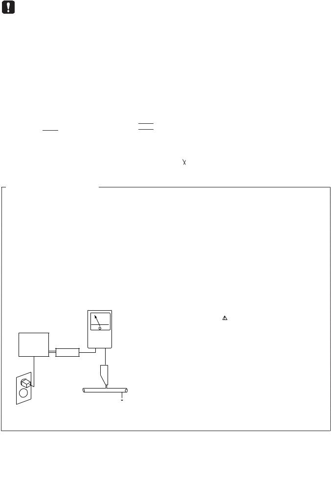
AC Leakage Test
F
2 |
DVJ-1000 |
||
|
|
|
|
1 |
2 |
3 |
4 |

5 |
6 |
7 |
8 |
IMPORTANT
THIS PIONEER APPARATUS CONTAINS LASER OF CLASS 1.
SERVICING OPERATION OF THE APPARATUS S H O U L D B E D O N E B Y A S P E C I A L LY INSTRUCTED PERSON.
WARNING !
LASER DIODE CHARACTERISTICS
MAXIMUM OUTPUT POWER : 5 mW WAVELENGTH : 780 – 785 nm
THE AEL (ACCESSIBLE EMISSION LEVEL) OF THE LASER POWER OUTPUT IS LESS THAN CLASS 1 BUT THE LASER COMPONENT IS CAPABLE OF EMITTING RADIATION EXCEEDING THE LIMIT FOR
CLASS 1.
A SPECIALLY INSTRUCTED PERSON SHOULD DO SERVICING OPERATION OF THE APPARATUS.
LABEL CHECK (for WYXJ5, KUCXJ and TLXJ/RD types)
for WYXJ5, KUCXJ and TLXJ/RD types
A
B
(DRW2317)
C
D
for TLFXJ type
5
Additional Laser Caution
1.Laser Interlock Mechanism
The position of the switch (S2401) for detecting loading completion is detected by the system microprocessor, and the
design prevents laser diode oscillation when the switch is not in LPS1 terminal side (when the mechanism is not clamped and LPS1 signal is high level.)
Thus, the interlock will no longer function if the switch is deliberately set to LPS1 terminal side. ( if LPS1 signal is low level ).
In the test mode the interlock mechanism will not function. Laser diode oscillation will continue, if pin 5 of AN22022A (IC7000) on the DVPL Assy is connected to GND, or else the terminals of Q7001(Q7002) are shorted to each other (fault condition).
2.When the cover is opened, close viewing of the objective lens with the naked eye will cause exposure to a Class 1 laser beam.
(VRW2159)
|
|
|
|
|
3 |
|
DVJ-1000 |
7 |
|||
|
|
||||
6 |
|
|
|
8 |
|
E
F
1 |
2 |
3 |
4 |
[Important Check Points for Good Servicing]
In this manual, procedures that must be performed during repairs are marked with the below symbol. Please be sure to confirm and follow these procedures.
A |
1. Product safety |
Please conform to product regulations (such as safety and radiation regulations), and maintain a safe servicing environment by following the safety instructions described in this manual.
1 Use specified parts for repair.
Use genuine parts. Be sure to use important parts for safety.
2 Do not perform modifications without proper instructions.
Please follow the specified safety methods when modification(addition/change of parts) is required due to interferences such as radio/TV interference and foreign noise.
3 Make sure the soldering of repaired locations is properly performed.
B
When you solder while repairing, please be sure that there are no cold solder and other debris. Soldering should be finished with the proper quantity. (Refer to the example)
4 Make sure the screws are tightly fastened.
Please be sure that all screws are fastened, and that there are no loose screws.
5 Make sure each connectors are correctly inserted.
Please be sure that all connectors are inserted, and that there are no imperfect insertion.
6 Make sure the wiring cables are set to their original state.
Please replace the wiring and cables to the original state after repairs. In addition, be sure that there are no pinched wires, etc.
C
7 Make sure screws and soldering scraps do not remain inside the product.
Please check that neither solder debris nor screws remain inside the product.
8 There should be no semi-broken wires, scratches, melting, etc. on the coating of the power cord.
Damaged power cords may lead to fire accidents, so please be sure that there are no damages.
If you find a damaged power cord, please exchange it with a suitable one.
9 There should be no spark traces or similar marks on the power plug.
When spark traces or similar marks are found on the power supply plug, please check the connection and advise on secure connections and suitable usage. Please exchange the power cord if necessary.
0 Safe environment should be secured during servicing.
D
When you perform repairs, please pay attention to static electricity, furniture, household articles, etc. in order to prevent injuries.
Please pay attention to your surroundings and repair safely.
2. Adjustments
To keep the original performance of the products, optimum adjustments and confirmation of characteristics within specification. Adjustments should be performed in accordance with the procedures/instructions described in this manual.
3. Lubricants, Glues, and Replacement parts
Use grease and adhesives that are equal to the specified substance.


 Make sure the proper amount is applied.
E
4. Cleaning
For parts that require cleaning, such as optical pickups, tape deck heads, lenses and mirrors used in projection monitors, proper cleaning should be performed to restore their performances.
5. Shipping mode and Shipping screws
To protect products from damages or failures during transit, the shipping mode should be set or the shipping screws should be installed before shipment. Please be sure to follow this method especially if it is specified in this manual.
F
4 |
DVJ-1000 |
||
|
|
|
|
1 |
2 |
3 |
4 |

5 |
6 |
7 |
8 |
CONTENTS |
|
|
|
SAFETY INFORMATION...................................................................................................................................... |
|
|
2 |
1. SPECIFICATIONS ............................................................................................................................................. |
|
|
6 |
2. EXPLODED VIEWS AND PARTS LIST............................................................................................................. |
|
|
8 |
2.1 PACKING .................................................................................................................................................... |
|
|
8 |
2.2 EXTERIOR SECTION .............................................................................................................................. |
|
|
10 |
2.3 CONTROL PANEL SECTION................................................................................................................... |
|
|
12 |
2.4 JOG SECTION ......................................................................................................................................... |
|
|
14 |
2.5 SLOT-IN MECHANISM SECTION ............................................................................................................ |
|
|
16 |
3. BLOCK DIAGRAM AND SCHEMATIC DIAGRAM .......................................................................................... |
|
20 |
|
3.1 BLOCK DIAGRAM (1/2) ........................................................................................................................... |
|
|
20 |
3.2 BLOCK DIAGRAM (2/2) ........................................................................................................................... |
|
|
22 |
3.3 OVERALL WIRING DIAGRAM ................................................................................................................. |
|
|
24 |
3.4 MAIN ASSY (1/8)...................................................................................................................................... |
|
|
26 |
3.5 MAIN ASSY(2/8)....................................................................................................................................... |
|
|
30 |
3.6 MAIN ASSY(3/8)....................................................................................................................................... |
|
|
32 |
3.7 MAIN ASSY(4/8)....................................................................................................................................... |
|
|
34 |
3.8 MAIN ASSY(5/8)....................................................................................................................................... |
|
|
36 |
3.9 MAIN ASSY(6/8)....................................................................................................................................... |
|
|
38 |
3.10 MAIN ASSY(7/8)..................................................................................................................................... |
|
|
40 |
3.11 MAIN ASSY(8/8)..................................................................................................................................... |
|
|
42 |
3.12 DVPL ASSY ............................................................................................................................................ |
|
|
46 |
3.13 STCN, SPCN, INSW and SDCB ASSYS................................................................................................ |
|
48 |
|
3.14 MJCB ASSY ........................................................................................................................................... |
|
|
50 |
3.15 AUDB and AJCB ASSYS........................................................................................................................ |
|
|
52 |
3.16 JFLB and JOGB ASSYS......................................................................................................................... |
|
|
54 |
3.17 DIPB and PSWB ASSYS........................................................................................................................ |
|
|
56 |
3.18 DFLB ASSY ............................................................................................................................................ |
|
|
58 |
3.19 KSWB and SLMB ASSYS ...................................................................................................................... |
|
|
60 |
3.20 SLDB, LED1, LED2 and PSWB ASSYS................................................................................................. |
|
62 |
|
3.21 POWER SUPPLY ASSY ......................................................................................................................... |
|
|
63 |
3.22 WAVEFORMS......................................................................................................................................... |
|
|
64 |
3.23 VOLTAGES.............................................................................................................................................. |
|
|
73 |
4. PCB CONNECTION DIAGRAM ...................................................................................................................... |
|
|
77 |
4.1 MAIN ASSY .............................................................................................................................................. |
|
|
78 |
4.2 DVPL ASSY .............................................................................................................................................. |
|
|
82 |
4.3 SPCN, STCN, INSW and SDCB ASSYS.................................................................................................. |
|
84 |
|
4.4 MJCB ASSY ............................................................................................................................................. |
|
|
86 |
4.5 JFLB ASSY............................................................................................................................................... |
|
|
88 |
4.6 DIPB and RSWB ASSYS.......................................................................................................................... |
|
|
90 |
4.7 SLDB, LED1 and LED2 ASSYS ............................................................................................................... |
|
|
94 |
4.8 KSWB ASSY............................................................................................................................................. |
|
|
96 |
4.9 AJCB, SLMB, JOGB and PSWB ASSYS ................................................................................................. |
|
98 |
|
4.10 POWER SUPPLY ASSY ....................................................................................................................... |
|
|
100 |
4.11 AUDB ASSY ......................................................................................................................................... |
|
|
102 |
5. PCB PARTS LIST .......................................................................................................................................... |
|
|
103 |
6. ADJUSTMENT .............................................................................................................................................. |
|
|
110 |
7. GENERAL INFORMATION ........................................................................................................................... |
|
|
113 |
7.1 DIAGNOSIS............................................................................................................................................ |
|
|
113 |
7.1.1 SERVICE MODE .............................................................................................................................. |
|
|
113 |
7.1.2 HOW TO UPGRADE THE SOFTWARE OF THE MICROCOMPUTER ........................................... |
119 |
||
7.1.3 HOW TO INPUT THE ID NUMBER .................................................................................................. |
|
|
120 |
7.1.4 SEQUENCE ..................................................................................................................................... |
|
|
122 |
7.1.5 DVJ-1000 BLOCK CHART (DJ MODE)............................................................................................ |
|
124 |
|
7.1.6 DVJ-1000 BLOCK CHART (NORMAL MODE)................................................................................. |
|
126 |
|
7.1.7 DISASSEMBLY ................................................................................................................................ |
|
|
128 |
7.3 PARTS .................................................................................................................................................... |
|
|
140 |
7.3.1 IC...................................................................................................................................................... |
|
|
140 |
8. PANEL FACILITIES ....................................................................................................................................... |
|
|
156 |
A
B
C
D
E
F
|
|
|
|
|
|
5 |
|
|
DVJ-1000 |
7 |
|||
|
|
|
||||
5 |
6 |
|
|
|
8 |
|

1 |
2 |
3 |
4 |
1. SPECIFICATIONS
A
Specifications
1. General
System ............................................................... |
|
DVD-Video, CD |
Power requirements ................ |
|
AC 220 V to 240 V, 50 Hz/60 Hz |
Power consumption .......................................................... |
|
40 W |
Operating temperature |
...................................... +5 ˚C to +35 ˚C |
|
Operating humidity ................................................. |
|
5 % to 85 % |
(There should be no condensation of moisture.) |
||
Weight .............................................................................. |
|
5.4 kg |
B Dimensions .............. |
320 mm (W) 408 mm (D) 109 mm (H) |
|
2. Video Output
Composite output (2) |
1 V p-p (75 Ω) |
Output level ..................................................... |
|
Jack ................................................ |
RCA jack(1), BNC jack(1) |
S-Video output |
1 V p-p (75 Ω) |
Y (luminance) ................................................... |
|
C (color) ........................................ |
286 mV p-p (75 Ω) (NTSC) |
|
300 mV p-p (75 Ω) (PAL) |
Jack ................................................................ |
4-pin mini DIN |
C 3. Preview Video Output
Composite output |
1 V p-p (75 Ω) |
Output level ..................................................... |
|
Jack ......................................................................... |
RCA jack |
S-Video output |
1 V p-p (75 Ω) |
Y (luminance) ................................................... |
|
C (color) ........................................ |
286 mV p-p (75 Ω) (NTSC) |
|
300 mV p-p (75 Ω) (PAL) |
Jack ................................................................ |
4-pin mini DIN |
4. Audio Output |
|
|
Audio output (2 channels) |
|
|
Output level ......................................... |
|
2 V rms (1 kHz, 0 dB) |
Channels .............................................................................. |
|
2 |
Jack ......................................................................... |
|
RCA jack |
Digital audio output |
|
|
Frequency response (CD) .............................. |
|
4 Hz to 20 kHz |
Frequency response (DVD, 96 kHz) |
............... 4 Hz to 44 kHz |
|
Signal-to-noise ratio .......................... |
|
115 dB or more (JEITA) |
Distortion ..................................................... |
|
0.004 % (JEITA) |
Digital output |
|
|
Jack ......................................................................... |
|
RCA jack |
5. Other jacks |
|
|
CONTROL jack ................................ |
Mini phone jack (ø3.5 mm) |
|
SYNC IN jack ............................................................... |
|
BNC jack |
6. Accessories |
|
|
Audio cable .......................................................................... |
|
1 |
Video cable .......................................................................... |
|
1 |
Control cord ......................................................................... |
|
1 |
Power cord .......................................................................... |
|
1 |
Forced eject pin ................................................................... |
|
1 |
(housed in a groove in the bottom panel) |
||
Operating instructions ......................................................... |
|
1 |
Note:
Specifications and design are subject to possible modification without notice.
D
E
F
6 |
DVJ-1000 |
||
|
|
|
|
1 |
2 |
3 |
4 |

5 |
6 |
7 |
8 |
A
Accessories
Audio Cable
(VDE1064) L=1.5m
Control Cord (XDE3063) L=1 m
Video Cable
(VDE1065) L=1.5m
Power Cord |
Forced Eject Pin |
(ADG7021 : KUCXJ) |
|
(ADG7097 : TLFXJ) |
(housed in a groove in |
|
the bottom panel) |
|
(DEX1021) |
|
B |
(ADG1154 : WYXJ5,TLFXJ |
|
TLXJ/RD) |
|
C
D
E
F
|
|
|
|
|
|
7 |
|
|
DVJ-1000 |
7 |
|||
|
|
|
||||
5 |
6 |
|
|
|
8 |
|

|
1 |
2 |
3 |
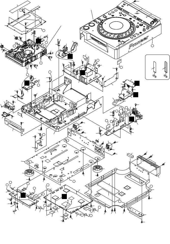
2. EXPLODED VIEWS AND PARTS LIST |
|||
NOTES: |
Parts marked by "NSP" are generally unavailable because they are not in our Master Spare Parts List. |
||
|
The |
mark found on some component parts indicates the importance of the safety factor of the part. |
|
A |
Therefore, when replacing, be sure to use parts of identical designation. |
|
|
|
Screws adjacent to mark on product are used for disassembly. |
|
|
 For the applying amount of lubricants or glue, follow the instructions in this manual. (In the case of no amount instructions, apply as you think it appropriate.)
2.1 PACKING
B
|
18 |
6 |
11 |
9
3
C
4
2
1
1
D
17
15
E
F
8 |
DVJ-1000 |
||
|
|
|
|
4
12
14
16
8
13
14
1 |
2 |
3 |
4 |

|
|
5 |
6 |
PACKING parts List |
|
||
Mark No. |
Description |
Part No. |
|
> |
1 |
AC Power Cord |
See Contrast table(2) |
|
2 |
Control Cord (L= 1m) |
XDE3063 |
|
3 |
Audio Cable (L= 1.5m) |
VDE1064 |
|
4 |
Video Cable (L=1.5m) |
VDE1065 |
|
5 |
• • • • • |
|
NSP |
6 |
Warranty Card |
See Contrast table(2) |
|
7 |
• • • • • |
|
|
8 |
Forced Eject Pin |
DEX1021 |
|
9 |
Operating Instructions(English) |
See Contrast table(2) |
|
10 |
• • • • • |
|
|
7 |
8 |
Mark No. |
Description |
Part No. |
NSP 11 |
Polyethylene Bag |
AHG7117 |
|
(230 x 340 x 0.06) |
|
12 |
Pad (A) |
DHA1716 |
13 |
Pad (B) |
DHA1717 |
14 |
Pad (C) |
DHA1718 |
15 |
Packing Case |
See Contrast table(2) |
16 |
Mirror mat Sheet |
AHG7010 |
17 |
Label |
See Contrast table(2) |
NSP 18 |
User Card |
DRM1262 |
(2) CONTRAST TABLE
DVJ-1000/KUCXJ, /WYXJ5, /TLXJ/RD and TLFXJ types are constructed the same except for the following:
Mark |
No. |
Symbol and Description |
DVJ-1000 |
DVJ-1000 |
DVJ-1000 |
DVJ-1000 |
|
/KUCXJ |
/WYXJ5 |
/TLXJ/RD |
/TLFXJ |
||||
|
|
|
|||||
|
|
|
|
|
|
|
|
> |
1 |
AC Power Cord |
ADG7021 |
ADG1154 |
ADG1154 |
ADG1154 |
|
> |
1 |
AC Power Cord |
Not used |
Not used |
Not used |
ADG7097 |
|
NSP |
6 |
Warranty Card |
ARY7043 |
Not used |
Not used |
Not used |
|
|
9 |
Operating Instructions (English)(KUCXJ) |
DRB1413 |
Not used |
Not used |
Not used |
|
|
9 |
Operating Instructions (WYXJ5)(English, |
Not used |
DRB1414 |
Not used |
Not used |
|
|
|
French, German, Italian, Dutch, Spanish) |
|
|
|
|
|
|
9 |
Operating Instructions (TLFXJ) |
Not used |
Not used |
Not used |
DRB1415 |
|
|
|
(English, Chinese) |
|
|
|
|
|
|
9 |
Operating Instructions (TLXJ/RD) |
Not used |
Not used |
DRB1416 |
Not used |
|
|
|
(English, Spanish) |
|
|
|
|
|
|
15 |
Packing Case |
DHG2636 |
DHG2637 |
DHG2639 |
DHG2638 |
|
NSP |
17 |
Label |
DRW2311 |
VRW1629 |
VRW1629 |
VRW1629 |
|
|
|
|
|
|
|
|
|
|
|
|
|
|
9 |
|
|
DVJ-1000 |
7 |
|||
|
|
|
||||
5 |
6 |
|
|
|
8 |
|
A
B
C
D
E
F
|
1 |
|
2 |
3 |
|
2.2 EXTERIOR SECTION |
|
||
A |
62 |
|
Refer to |
58 |
|
|
|||
|
|
|
"2.3 CONTROL PANEL SECTION". |
|
|
C |
|
63 |
|
|
|
57 |
Refer to "2.5 SLOT-IN |
|
|
52 |
MECHANISM SECTION". |
|
|
|
|
|
||
|
|
|
|
|
|
D |
20 |
||
|
49 |
51 |
50 |
|
3 |
|
|||
|
|
|
|
|
|
||||
|
|
|
|
|
|
|
|
||
49 |
|
61 |
|
|
E |
E |
|
53 |
|
B |
F |
|
|
|
|
H |
|
|
|
|
|
|
|
|
|
|
|||
|
|
|
|
|
|
|
|
|
51 |
51 |
|
|
|
|
|
|
|
|
|
|
|
|
|
|
I |
|
|
|
49 |
|
|
|
51 |
49 |
|
|
|
C |
|
|
|
|
G 57 |
|
|
|
|
|
|
|
|
|
|
|
58 |
|
|
|
|
|
|
|
|
19 |
|
|
|
||
|
|
|
F |
|
|
18 |
|
|
|
|
|
60 |
|
J |
|
|
|
|
|
C |
57 |
|
|
|
|
|
|
|
|
|
5 |
|
55 |
|
|
|
|
||
|
|
|
|
|
|
|
|
||
44 |
|
|
|
|
|
|
|
||
|
|
|
|
|
|
|
|
||
45 |
57 |
|
|
|
|
|
|
|
|
30 |
|
|
|
|
|
|
|
||
|
25 |
|
|
|
|
|
|
|
|
26 |
|
64 |
|
|
|
|
|
|
|
|
|
58 |
|
|
|
|
|
|
|
|
37 |
|
|
56 |
|
|
|
|
|
D |
|
|
58 |
D |
|
|
|
||
|
|
|
|
|
41 |
||||
|
|
|
57 |
|
|
|
|
||
|
|
|
|
|
|
|
|
||
|
|
|
|
|
|
|
|
|
|
|
|
|
|
|
|
18 |
|
|
|
|
|
|
38 |
|
|
|
|
|
|
|
|
48 |
|
|
|
|
|
|
|
|
|
47 |
|
|
|
|
|
|
|
E |
|
57 |
|
|
|
|
|
|
|
|
|
|
|
|
|
|
|
||
E |
F |
12 |
H |
|
57 |
|
J |
|
|
61 |
|
G |
|
|
|
14 |
|||
|
|
|
|
|
|
|
|
||
|
|
|
10 |
|
|
|
|
|
|
20 |
|
|
|
|
|
|
|
|
|
|
B |
|
|
|
I |
|
|
|
|
|
|
|
|
|
|
|
|
||
28 |
|
|
|
13 |
|
|
|
||
|
|
|
|
|
|
|
|||
58 |
|
|
|
|
58 |
27 |
|||
|
|
|
|
|
K |
||||
|
2 |
|
|
|
|
|
|
||
|
53 |
|
|
|
|
|
|
||
|
|
|
|
|
|
|
|
|
|
|
|
58 |
|
58 |
23 |
58 |
|
|
|
|
29 |
|
|
|
|
|
|
||
|
|
|
|
|
|
|
|
|
|
11
F
58 |
24 |
|
|
|
|
|
|
|
|
|
|
|
7 |
|
|
|
|
|
|
|
|
|
|
|
|
|
|
|
|
|
|
|
|
|
|
|
S |
65 |
|
|
|
|
|
|
|
|
|
|
57 |
Q |
|
|
|
|
|
|
|
||
|
57 60 |
|
|
|
|
|
|
|
|
|
|
|
|
|
|
54 |
|
|
|
|
|
|
|
|
|
|
|
|
|
|
|
R |
|
|
|
|
|
|
|
|
|
60 |
|
|
|
||
|
|
|
T |
|
57 |
|
|
|
|
|
|
|
|
|
|
|
|
|
|
9 |
|
||
|
|
|
|
|
|
|
|
|
|
|
|
|
|
6 |
|
P |
|
|
|
|
32 |
|
R |
|
|
|
|
|
|
36 |
|
||||
|
|
|
|
|
|
|
57 |
|
32 |
||
|
|
|
|
|
|
|
|
|
|
|
|
|
|
|
|
|
|
|
17 |
57 |
|
Q |
|
|
|
|
|
|
|
|
|
|
|
||
|
|
|
|
|
|
|
|
|
|
8 |
|
|
|
|
|
|
|
|
|
N |
|
21 |
|
|
|
|
|
|
|
|
|
|
15 |
57 |
|
|
|
|
|
|
|
|
|
|
|
||
|
|
|
|
|
|
|
|
|
M |
O |
|
|
|
|
|
|
|
57 |
|
|
K |
|
|
|
|
|
|
|
|
|
|
|
|
|
|
|
|
|
|
|
|
53 |
L |
|
Q |
G |
|
|
|
|
|
|
|
R |
P |
|
|||
|
|
|
|
|
|
|
|
|
|
||
|
|
|
58 |
|
|
|
|
|
|
|
4 |
|
|
|
42 |
|
|
|
|
|
|
|
|
|
|
|
58 |
|
57 |
|
|
|
|
57 |
|
|
|
|
57 |
53 |
|
|
|
|
53 |
||
|
|
|
|
|
|
|
|
|
|||
|
|
|
|
40 |
57 |
43 |
|
|
|
|
|
|
|
|
|
|
|
|
58 |
|
|
||
|
|
|
|
|
|
|
|
|
|
|
|
|
|
|
|
|
|
|
|
58 |
34 |
|
|
|
|
|
|
|
|
|
|
|
57 |
|
|
|
|
|
|
|
|
|
|
|
|
|
|
|
|
|
|
|
47 |
|
|
|
|
|
|
|
|
|
57 |
57 |
|
|
|
|
|
|
|
|
|
|
|
|
|
|
|
|
|
|
|
|
|
B |
|
|
|
33 |
|
|
|
|
|
|
|
|
1 |
|
|
|
|
|
|
|
|
|
A |
|
|
|
|
|
|
|
|
|
|
|
|
|
|
|
|
|
|
|
B |
|
|
|
|
|
|
58 N |
|
|
|
|
|
|
|
31 |
|
|
|
O |
|
|
|
|
|
|
|
|
|
L |
21 |
58 |
|
58 |
56 58 |
|
|
||
27 |
|
16 |
M |
|
|
|
|||||
|
31 |
22 |
|
|
|
|
|
|
|
|
|
58 |
58 |
|
|
|
|
|
|
|
|
||
|
|
|
|
|
|
|
|
|
|||
10 |
DVJ-1000 |
||
|
|
|
|
4
A
NON-CONTACT SIDE |
CONTACT SIDE |
58
60
58
35
 A
A
39
56
46
58
1 |
2 |
3 |
4 |
|
|
5 |
6 |
EXTERIOR SECTION parts List |
|
||
Mark No. |
Description |
Part No. |
|
|
1 |
MAIN Assy |
DWG1630 |
|
2 |
DVPL Assy |
DWX2627 |
|
3 |
SLMB Assy |
DWS1395 |
|
4 |
MJCB Assy |
DWG1633 |
|
5 |
SDCB Assy |
DWX2630 |
> |
6 |
POWER SUPPLY Assy |
DWR1436 |
> |
7 |
PSWB Assy |
See Contrast table(2) |
|
8 |
AUDB Assy |
DWG1638 |
|
9 |
AJCB Assy |
DWG1639 |
|
10 |
26P FFC/30V |
DDD1337 |
|
11 |
FFC/30V (40p) |
DDD1338 |
|
12 |
FFC/60V (13p) |
DDD1339 |
|
13 |
FFC/60V (4p) |
DDD1340 |
|
14 |
FFC/60V (13p) |
DDD1341 |
|
15 |
FFC/60V (27p) |
DDD1342 |
|
16 |
FFC/60V (10p) |
DDD1343 |
|
17 |
FFC/60V (9p) |
DDD1344 |
|
18 |
Earth Lead Unit |
DDF1032 |
|
19 |
Earth Lead Unit |
DDF1033 |
|
20 |
Connector Assy |
PF03PP-B35 |
|
21 |
Connector Assy |
DKP3778 |
|
22 |
6P Connector Assy |
PF06PP6D15 |
|
23 |
8P Connector Assy |
PF08PP-D25 |
|
24 |
Power Knob |
DNK4635 |
|
25 |
Door Spring |
DBH1565 |
|
26 |
Card Door |
DNK4651 |
|
27 |
Earth Plate 1(CU) |
DBK1300 |
|
28 |
Earth Plate 2(CU) |
DBK1301 |
NSP 29 |
Silicon Rubber D5 L |
DEB1456 |
|
|
30 |
Door Cushion |
DEB1780 |
|
31 |
Insulation Sheet |
DEC2694 |
|
32 |
PC Support |
DEC2736 |
|
33 |
Shield Cushion |
DEC2905 |
|
34 |
Gasket L40 |
DEC2979 |
|
|
7 |
8 |
Mark No. |
Description |
Part No. |
|
|
35 |
Heat Sink |
DNG1098 |
NSP |
36 |
Shield Plate 2 |
DNH2723 |
NSP |
37 |
Front Plate |
DNH2724 |
NSP |
38 |
Earth Plate |
DNH2726 |
|
39 |
Heat Plate |
See Contrast table(2) |
|
40 |
Blind Cap |
DNK4218 |
NSP 41 |
Chassis |
DNK4591 |
|
|
42 |
Rear Protector (R) |
DNK4636 |
|
43 |
Rear Protector (L) |
DNK4637 |
|
44 |
Card Plate |
DBK1296 |
|
45 |
Door Holder |
DNK4652 |
|
46 |
Push Rod Holder |
DNK4671 |
|
47 |
Insulator Assembly |
DXA1904 |
|
48 |
Shield Plate 1 Assy |
See Contrast table(2) |
|
49 |
Damper |
CNV6011 |
|
50 |
Earth Spring |
DBH1398 |
|
51 |
Float Spring G11 |
DBH1526 |
|
52 |
Mecha Plate |
DNH2339 |
|
53 |
Cord Clamper (STEEL) |
RNH-184 |
|
54 |
Binder |
ZCA-SKB90BK |
|
55 |
DM Screw (FTC) |
DBA1260 |
|
56 |
Screw |
BPZ30P120FTB |
|
57 |
Screw |
BPZ30P080FTB |
|
58 |
Screw |
BBZ30P080FTC |
|
59 |
Screw |
BPZ30P080FZK |
|
60 |
Screw |
BBZ30P140FTC |
|
61 |
2P Connector |
PF02PY-B37 |
|
62 |
Laser Caution (7L) |
See Contrast table(2) |
|
63 |
Guard Cushion |
DEC2984 |
|
64 |
Door Plate |
DNK4650 |
|
65 |
Shield Sheet Assy |
DXB1941 |
A
B
C
D
(2) CONTRAST TABLE
DVJ-1000/KUCXJ, /WYXJ5, /TLXJ/RD and TLFXJ types are constructed the same except for the following:
Mark |
No. |
Symbol and Description |
DVJ-1000 |
DVJ-1000 |
DVJ-1000 |
DVJ-1000 |
|
/KUCXJ |
/WYXJ5 |
/TLXJ/RD |
/TLFXJ |
||||
|
|
|
|||||
|
|
|
|
|
|
|
|
> |
7 |
PSWB ASSY |
DWS1392 |
DWS1396 |
DWS1396 |
DWS1396 |
|
|
39 |
Heat Plate |
DNH2744 |
DNH2749 |
DNH2750 |
DNH2750 |
|
|
48 |
Shield Plate 1 Assy |
DXB1883 |
DXB1892 |
DXB1894 |
DXB1893 |
|
|
62 |
Laser Caution |
DRW2317 |
DRW2317 |
DRW2317 |
VRW2159 |
|
|
|
|
|
|
|
|
E
F
|
|
|
|
|
|
11 |
|
|
DVJ-1000 |
7 |
|||
|
|
|
||||
5 |
6 |
|
|
|
8 |
|
1 |
2 |
3 |
4 |
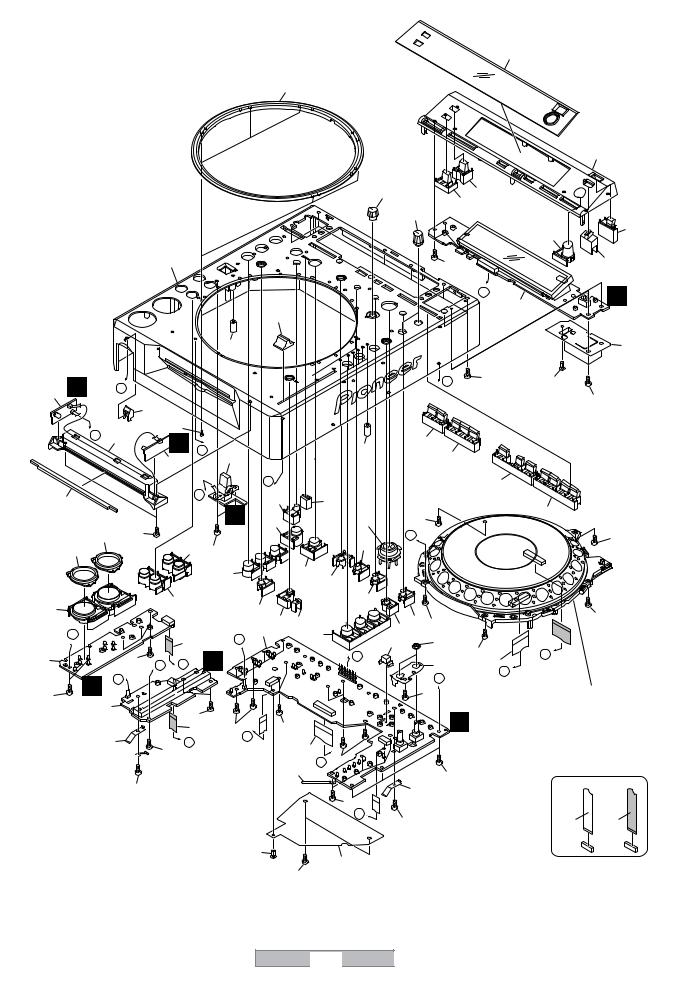
2.3 CONTROL PANEL SECTION
A |
|
|
|
|
|
|
|
|
|
|
|
|
|
|
|
|
|
|
|
|
|
|
|
|
|
|
|
|
|
13 |
|
|
|
|
|
|
|
|
|
|
19 |
|
|
|
|
|
|
|
|
|
|
|
|
|
|
|
|
|
|
|
|
|
|
|
|
|
14 |
|
|
|
|
|
|
|
|
|
12 |
|
|
59 |
|
|
|
|
B |
|
|
|
|
|
|
|
|
|
17 |
|
60 |
|
|
|
|
|
|
|
|
|
|
|
|
|
|
|
|
|
|
|
|
|
|
|
|
|
|
|
|
|
|
|
|
|
|
|
16 |
|
61 |
|
|
|
|
|
|
|
|
|
|
|
|
|
|
|
|
|
|
|
|
|
20 |
|
|
|
|
|
|
56 |
|
|
|
|
15 |
|
|
|
|
|
|
|
|
|
|
|
|
A |
|
|
|
N |
|
|
|
|
|
|
|
|
|
|
|
|
|
|
6 |
|
|
|
|
|
|
|
|
|
18 |
|
|
|
|
|
|
|
|
|
|
|
|
|
|
|
|
|
|
|
|
|
|
|
|
|
|
|
|
|
|
|
|
29 |
|
|
|
|
|
|
|
|
|
44 |
C |
K |
|
F |
|
|
|
|
|
|
|
B |
56 |
58 |
|
|
|
5 |
|
|
|
|
|
|
|
|
|
|
|
|
||||
|
|
|
|
|
|
|
|
|
|
|
|
|
56 |
|||
|
|
|
24 |
|
|
|
|
|
|
|
|
|
|
|
|
|
|
|
|
|
|
|
|
|
|
|
|
|
|
|
|
|
|
|
G |
|
|
62 |
|
|
|
|
|
|
|
|
|
|
|
|
|
41 |
L |
|
|
|
|
29 |
25 |
|
|
|
|
|
|||
|
|
|
|
E |
|
|
|
|
|
|
|
|||||
|
|
|
|
|
|
|
26 |
|
|
|
|
|
||||
|
|
|
|
4 |
|
2 |
|
|
|
|
|
|
|
|
|
|
|
|
|
|
D |
|
C |
|
|
|
|
|
27 |
|
|
|
|
|
42 |
|
|
|
34 |
|
63 |
|
|
|
|
|
|
|
||
|
|
|
|
|
O |
|
|
|
|
|
|
|
|
|||
|
|
|
|
|
|
|
|
|
|
|
28 |
|
|
|||
|
|
|
|
|
|
32 |
|
37 |
56 |
|
|
|
|
|
||
|
|
|
56 |
|
|
|
|
|
|
|
|
|
||||
D |
45 |
47 |
|
|
|
|
34 |
E |
|
|
|
|
|
56 |
||
45 |
|
|
|
56 |
|
|
|
|
|
|
|
|
|
|||
|
|
|
|
|
|
|
|
|
|
|
|
|
||||
|
|
|
|
|
|
30 |
|
32 |
33 |
|
|
|
|
|
|
|
|
|
|
|
|
|
|
|
|
|
|
|
|
|
|
|
|
47 |
|
|
|
47 |
|
|
31 |
|
35 |
|
|
|
|
|
|
|
|
|
|
|
|
|
|
|
|
|
|
|
|
|
56 |
||
|
|
|
|
|
|
|
50 |
51 |
|
34 |
56 |
|
|
|
|
|
|
|
|
|
|
|
|
|
|
|
|
|
|
||||
|
F |
|
|
|
|
D |
1 |
39 |
38 |
|
|
|
|
|
|
|
|
|
|
11 |
|
|
52 |
|
54 |
|
|
|
|
|
|||
|
|
|
|
|
|
|
|
56 |
|
|
|
|
||||
7 |
|
|
56 |
H |
|
M |
|
|
A |
|
53 |
8 |
J |
|
|
|
|
|
C |
|
|
|
|
|
|
|
|
|
|||||
|
P |
|
G |
|
|
|
|
|
|
56B |
|
R |
|
|
|
|
56 |
|
|
|
|
|
|
|
|
|
Refer to |
|
|||||
|
3 |
|
|
|
|
|
|
|
|
|
|
|
"2.4 JOG SECTION". |
|||
|
|
|
|
|
|
|
|
|
|
|
|
|
||||
|
|
|
56 |
|
|
|
|
|
|
I |
|
|
|
|
||
E |
|
|
|
|
|
|
|
|
|
|
|
|
|
|||
|
|
|
10 |
56 |
56 |
|
|
|
|
|
|
|
||||
|
|
|
|
|
|
|
|
|
|
|
||||||
|
|
49 |
|
I |
|
|
H |
|
|
|
|
|
|
|
|
|
|
|
|
|
|
|
9 |
|
|
|
|
|
|
|
|
||
|
|
|
|
56 |
|
|
|
56 |
|
|
|
|
|
|
|
|
|
|
|
|
|
|
|
|
J |
|
|
|
|
|
|
|
|
|
|
|
|
|
|
|
55 |
|
|
56 |
|
|
|
|
|
|
|
|
|
|
|
|
|
|
|
|
|
|
|
NON-CONTACT |
|
|
|
|
|
|
56 |
|
|
|
|
|
|
49 |
|
|
|
|
CONTACT SIDE |
|
|
|
|
|
|
|
|
|
|
56 |
|
|
|
|
|
||
|
|
|
|
|
|
|
|
|
I |
56 |
|
|
|
|
||
|
|
|
|
|
|
|
|
|
|
|
|
|
SIDE |
|||
|
|
|
|
|
|
|
58 |
|
36 |
|
|
|
|
|||
|
|
|
|
|
|
|
|
|
|
|
|
|
|
|
||
|
|
|
|
|
|
|
|
|
|
|
|
|
|
|
|
|
|
|
|
|
|
|
|
|
56 |
|
|
|
|
|
|
|
|
F |
|
|
|
|
|
|
|
|
|
|
|
|
|
|
|
|
12 |
|
|
|
|
|
|
|
DVJ-1000 |
|
|
|
|
|
|
|
|
|
1 |
|
|
|
|
2 |
|
|
3 |
|
|
|
|
|
4 |
|

|
|
|
|
5 |
6 |
|
7 |
8 |
|
CONTROL PANEL SECTION parts List |
|
|
|
||||||
Mark No. |
|
|
|
Description |
Part No. |
Mark No. |
Description |
Part No. |
|
1 |
DIPB Assy |
See Contrast table(2) |
33 |
RELOOP Knob |
DAC2325 |
||||
2 |
RSWB Assy |
DWS1391 |
34 |
ENTER Knob |
DAC2326 |
||||
3 |
SLDB Assy |
DWS1393 |
35 |
CALL Knob |
DAC2323 |
||||
4 |
LED 1 Assy |
DWG1634 |
|
|
|
||||
5 |
LED 2 Assy |
DWG1635 |
36 |
Shield Sheet 1 |
DEC2899 |
||||
|
|
|
|
|
|
37 |
Cross Key |
DAC2327 |
|
6 |
DFLB Assy |
DWG1632 |
38 |
Change Knob |
DAC2328 |
||||
7 |
KSWB Assy |
DWS1394 |
39 |
SET Knob (TEMPO) |
DAC2329 |
||||
8 |
22P FFC/60V |
DDD1345 |
40 |
• • • • |
|
||||
9 |
25P FFC/60V |
DDD1346 |
|
|
|
||||
10 |
10P FFC/60V |
DDD1347 |
41 |
Reflector |
DNK4597 |
||||
|
|
|
|
|
|
42 |
Front Lens |
DNK4595 |
|
11 |
9P FFC/60V |
DDD1348 |
43 |
• • • • |
|
||||
12 |
Adjust Knob |
DAC2350 |
44 |
Shield Sheet 2 |
DEC2909 |
||||
13 |
Display Panel(PMMA) |
DNK4601 |
45 |
Ring Lens |
DNK3880 |
||||
14 |
Top Panel |
DNK4599 |
|
|
|
||||
15 |
Slide SW Knob |
DNK4592 |
46 |
• • • • |
|
||||
|
|
|
|
|
|
47 |
SET Knob (PLAY) Assy |
DXB1912 |
|
16 |
Eject Knob |
DAC2335 |
48 |
• • • |
|
||||
17 |
Rotary Knob |
DAA1182 |
49 |
Earth Plate (CU) |
DBK1224 |
||||
18 |
Slide Knob |
DAC2376 |
50 |
RESET Knob |
DAC2330 |
||||
19 |
Jog Ring |
DNK4600 |
|
|
|
||||
20 |
Control Panel |
DNK4598 |
51 |
TEMPO RESET Lens |
DNK4708 |
||||
|
|
|
|
|
|
52 |
Cross Key Holder |
DNK4798 |
|
21 |
• |
• |
• |
• |
|
53 |
VR Stay |
DNF1663 |
|
|
|
|
|
||||||
22 |
• |
• |
• |
• |
|
54 |
Flange Nut M9 |
DBN1008 |
|
|
55 |
Cord Clamper (steel) |
RNH-184 |
||||||
23 |
• |
• |
• |
• |
|
||||
|
|
|
|
||||||
24 |
Card Lens |
DNK4596 |
56 |
Screw |
BPZ30P080FTB |
||||
25 |
SETKnob 1 |
DAC2331 |
|||||||
57 |
• • • • |
|
|||||||
|
|
|
|
|
|
|
|||
26 |
SETKnob 2 |
DAC2332 |
58 |
Rivet (PLASTIC) |
RBM-003 |
||||
59 |
TIMX Knob |
DAC2336 |
|||||||
27 |
SETKnob 3 |
DAC2333 |
|||||||
60 |
TEXT Knob |
DAC2338 |
|||||||
28 |
SETKnob 4 |
DAC2334 |
|||||||
|
|
|
|||||||
29 |
TEMPO Lens |
DNK4593 |
61 |
STOP Knob |
DAC2354 |
||||
30 |
SET Knob (H. C.) |
DAC2321 |
|||||||
62 |
Screw |
OBA8038 |
|||||||
|
|
|
|
|
|
||||
31 |
REC Knob |
DAC2322 |
63 |
LOOP MODE Lens |
DNK4594 |
||||
|
|
|
|||||||
32 |
SET Knob (LOOP) |
DAC2324 |
|
|
|
||||
(2) CONTRAST TABLE
DVJ-1000/KUCXJ, /WYXJ5, /TLXJ/RD and TLFXJ types are constructed the same except for the following:
Mark |
No. |
Symbol and Description |
DVJ-1000 |
DVJ-1000 |
DVJ-1000 |
DVJ-1000 |
|
/KUCXJ |
/WYXJ5 |
/TLXJ/RD |
/TLFXJ |
||||
|
|
|
|||||
|
|
|
|
|
|
|
|
|
1 |
DIPB ASSY |
DWG1631 |
DWG1640 |
DWG1642 |
DWG1641 |
|
|
|
|
|
|
|
|
A
B
C
D
E
F
|
|
|
|
|
|
13 |
|
|
DVJ-1000 |
7 |
|||
|
|
|
||||
5 |
6 |
|
|
|
8 |
|

1
2.4 JOG SECTION
A
B
C
D
|
|
|
|
*1. |
Lubricating oil |
||
E |
GYA1001 (ZLB-PN397B) |
||
*2. Lubricants : (ZLB-HPD1600)
F
14
2 |
3 |
|
|
9 |
|
|
|
5 |
|
|
|
7 |
|
*2 |
|
*2 |
|
|
|
8 |
|
28 |
|
28 |
|
|
*2 |
||
|
|
||
|
14 |
28 |
|
11 |
12 |
||
|
|
||
|
|
14 |
|
14 |
|
17 |
|
17 |
13 |
||
|
|
17 |
|
3 |
A |
17 |
|
17 |
|||
|
17 |
||
|
15 |
||
|
|
||
|
|
40x8 |
|
|
13 |
|
|
27 |
|
|
|
|
|
|
|
|
39 |
|
|
16 |
|
|
|
|
|
18 |
|
|
|
|
38 |
|
|
|
|
|
37 |
|
|
27 |
|
|
|
|
|
|
30 |
|
|
|
|
|
|
19 |
|
|
|
36 |
|
|
20 |
J |
|
|
|
28 |
|
|
|
|
|
||
21 |
|
10 |
|
|
|
|
|
2 |
33 |
|
22 |
||
|
|
32 |
||||
27 |
A |
|
|
|
26 |
|
|
|
|
|
|||
|
|
|
|
23 |
||
|
|
|
|
|
|
|
*1 |
4 |
H |
|
|
|
34 |
|
|
|
35 |
|||
|
|
|
|
|
|
|
|
|
|
|
|
|
25 |
|
1 |
31 |
24 |
|
31 |
|
|
G MJCB to |
31 |
|
29 |
CN4508 |
|
|
|
DVJ-1000
4
NON-CONTACT SIDE |
CONTACT SIDE |
*1
31
IDIPB to CN3002
1 |
2 |
3 |
4 |

|
5 |
6 |
7 |
8 |
JOG SECTION parts List |
|
|
|
|
Mark No. |
Description |
Part No. |
|
|
1 |
JFLB Assy |
DWG1636 |
|
|
2 |
JOGB Assy |
DWG1637 |
|
|
3 |
Sheet SW |
DSX1065 |
|
|
4 |
Connector Assy |
PF04PP-B07 |
|
|
5 |
Jog Panel (PMMA) |
DAH2182 |
|
|
6 |
• • • • |
|
|
|
7 |
JOG Plate |
DAH2438 |
|
|
8 |
JOG A |
DNK4586 |
|
|
9 |
JOG B |
DNK4557 |
|
|
10 |
Protector Sheet |
DEC2945 |
|
|
11 |
SW Ring |
DNK4070 |
|
|
12 |
Roller A Assy |
DXB1825 |
|
|
13 |
SW Spring 25 |
DBH1514 |
|
|
14 |
Ring Cushion L24/2.0 |
DEC2958 |
|
|
15 |
JOG Stay Assy |
DXB1876 |
|
|
16 |
JOG Holder 1000 |
DNK4558 |
|
|
17 |
SW Cushion HH48/2 |
DEC2538 |
|
|
18 |
Arm Spring |
DBH1566 |
|
|
19 |
Gear |
DNK4560 |
|
|
20 |
ENCORDER Plate |
DEC2889 |
|
|
21 |
Gear Arm |
DNK4559 |
|
|
22 |
Load Gear A |
DNK4562 |
|
|
23 |
Smoother |
DNK4561 |
|
|
24 |
Adjust Plate |
DNK4178 |
|
|
25 |
Gear Spring 200 |
DBH1525 |
|
|
26 |
Washer |
WA52D120D025 |
|
|
27 |
Screw |
IPZ30P100FTC |
|
|
28 |
Screw (FE) |
DBA1265 |
|
|
29 |
Screw |
BPZ20P100FTC |
|
|
30 |
Screw |
BPZ20P060FTC |
|
|
31 |
Screw |
BPZ30P080FTB |
|
|
32 |
25P FFC / 60V |
DDD1346 |
|
|
33 |
FL Sheet |
DEC2946 |
|
|
34 |
CAM Plate |
DNK4567 |
|
|
35 |
PRESS Plate |
DNK4566 |
|
|
36 |
GEAR Plate |
DNH2713 |
|
|
37 |
Link Gear 3 |
DNK4565 |
|
|
38 |
Link Gear 2 |
DNK4564 |
|
|
39 |
Link Gear 1 |
DNK4563 |
|
|
40 |
Roller B Assy |
DXB1877 |
|
|
A
B
C
D
E
F
|
|
|
|
|
|
15 |
|
|
DVJ-1000 |
7 |
|||
|
|
|
||||
5 |
6 |
|
|
|
8 |
|

1 |
2 |
3 |
4 |
2.5 SLOT-IN MECHANISM SECTION
1 : |
Lubricating oil |
GYA1001 |
|
A |
|
2 : |
Daifree |
GEM1036 |
B
C
|
|
19 |
|
Refer to |
|
|
"2.6 TRAVERSE MECHA. |
|
|
ASSY-S". |
4 |
D |
|
21 |
|
|
|
|
B DVPL to |
16 |
|
CN7002 |
|
|
23 |
|
|
C |
2 |
E |
15 |
|
|
|
|
25 |
|
CONTACT-NON SIDE |
SIDECONTACT |
|
|
|
|
31 |
|
|
|
32 |
|
*1 |
|
36 |
33 |
34 |
|
35 |
|
30 |
|
37 |
|
|
1 1
2 
38
39
2
*2 |
40 |
2 |
|
|
B DVPL to |
|
|
|
|
|
CN7005 |
42 |
41 |
|
27 1 |
|
29 |
|
|
43 |
28 |
||
|
|
|
|||
|
|
|
26 |
|
|
20
18 20
19
|
21 |
5 |
6 |
23 |
16 |
|
B DVPL to |
|
CN7001 |
||
|
|
4
7 |
3 |
14 |
17 U
9 22
23
1
8
D
|
12 |
|
|
|
B DVPL to |
|
10 |
CN7003 |
|
13 |
|
|
|
|
F |
11 |
12 |
|
|
|
16 |
|
DVJ-1000 |
1 |
2 |
3 |
4 |

|
5 |
6 |
7 |
8 |
SLOT-IN MECHANISM SECTION parts List |
|
|
||
Mark No. |
Description |
Part No. |
|
|
1 |
STCN Assy |
DWX2628 |
|
|
2 |
SPCN Assy |
DWX2629 |
|
|
3 |
INSW Assy |
DWS1398 |
|
|
4 |
Traverse Mechanism G11 Assy-S DXX2566 |
|
|
|
NSP 5 |
Pickup Assy |
OWY8071 |
|
|
6 |
26P Flexible Cable/30V |
DDD1337 |
|
|
7 |
13P Flexible Cable/60V |
DDD1339 |
|
|
8 |
4P Flexible Cable/60V |
DDD1340 |
|
|
9 |
Connector Assy |
DKP3769 |
|
|
10 |
Vessel Cushion A |
DEC2852 |
|
|
11 |
Vessel Cushion B |
DEC2853 |
|
|
12 |
Vessel Cushion C |
DEC2854 |
|
|
13 |
Float Base (G11) Assy |
DXB1793 |
|
|
14 |
Spacer POR (T3) |
DEB1566 |
|
|
15 |
Front Sheet |
DED1132 |
|
|
16 |
Float Rubber D3 |
DEB1404 |
|
|
17 |
Inside SW Base |
DNK4236 |
|
|
18 |
Weight G11 |
DNH2775 |
|
|
NSP 19 |
DRA Rubber G5 |
DEB1454 |
|
|
20 |
DRA Screw R (G7) |
DBA1264 |
|
|
21 |
Float Fastener |
DBA1286 |
|
|
22 |
Screw |
VBA1062 |
|
|
23 |
Screw |
IPZ20P060FTC |
|
|
24 |
• • • • • |
|
|
|
NSP 25 |
Slot-in Mechanism G11 assy |
DXA2085 |
|
|
26 |
Loading Motor Assy-S |
DEA1008 |
|
|
NSP 27 |
Worm Gear |
DNK3910 |
|
|
NSP 28 |
DC Motor |
DXM1229 |
|
|
29 |
Connector Assy |
PF02PY-B37 |
|
|
30 |
Loading Base Assy-S |
DEA1022 |
|
|
31 |
Main Cam |
DNK3407 |
|
|
32 |
Driver Gear |
DNK3912 |
|
|
33 |
Loading Gear |
DNK3911 |
|
|
34 |
SW Lever Spacer |
DEC2420 |
|
|
35 |
Loading Lever Assy |
DXB1880 |
|
|
36 |
Clamper D4 Assy |
DXA2043 |
|
|
37 |
Clamper Spring |
DBH1374 |
|
|
38 |
Clamper Arm |
DNK3576 |
|
|
39 |
Eject Lever |
DNK3684 |
|
|
40 |
Lever AP |
DNK3835 |
|
|
41 |
Lever BP |
DNK3836 |
|
|
42 |
Guide Spring |
DBH1375 |
|
|
43 |
Disc Guide |
DNK3478 |
|
|
A
B
C
D
E
F
|
|
|
|
|
|
17 |
|
|
DVJ-1000 |
7 |
|||
|
|
|
||||
5 |
6 |
|
|
|
8 |
|

1 |
2 |
3 |
4 |
2.6 TRAVERSE MECHA ASSY-S SECTION
12
A
 1
1
B
5
C
|
8 |
1 |
4 |
D |
2 |
8
 2
2
E |
C SPCN to |
|
CN7402 |
13
13
F
1
D STCN to
CN7406
10
Cleaning paper
GED-008
Cleaning liquid
GEM1004
3
7
11 |
9 |
|
|
|
6 |
11
4
*1. Grease : GYA1001 (ZLB-PN397B)
*2. Grease : GEM1007 (ZLB-PN948P)
18 |
DVJ-1000 |
||
|
|
|
|
1 |
2 |
3 |
4 |

|
5 |
6 |
7 |
8 |
TRAVERSE MECHA ASSY-S SECTION parts List |
|
|
||
Mark No. |
Description |
Part No. |
|
|
NSP 1 |
Spindle Motor |
DXM1227 |
|
|
NSP 2 |
Stepping Motor |
DXM1231 |
|
|
NSP 3 |
Pickup Assy-S |
OXX8071 |
|
|
NSP 4 |
Skew Screw |
DBA1263 |
|
|
NSP 5 |
Skew Spring |
DBH1437 |
|
|
NSP 6 |
Joint Spring |
DBK1261 |
|
|
NSP 7 |
Leaf Spring G11 |
DBK1262 |
|
|
NSP 8 |
Guide Bar (S) |
DLA1918 |
|
|
9 |
Joint |
DNK3858 |
|
|
NSP 10 |
Mecha.Chassis G11 |
DNK4307 |
|
|
11 |
Tapping Screw 04 |
VBA1092 |
|
|
12 |
Screw |
BPZ20P080FTC |
|
|
13 |
Screw |
BPZ26P080FTC |
|
|
A
B
C
D
E
F
|
|
|
|
|
|
19 |
|
|
DVJ-1000 |
7 |
|||
|
|
|
||||
5 |
6 |
|
|
|
8 |
|

1 |
2 |
3 |
4 |
3. BLOCK DIAGRAM AND SCHEMATIC DIAGRAM
3.1 BLOCK DIAGRAM (1/2)
A
B DVPL ASSY |
A MAIN ASSY EDD5108AFTA-6B-E |
|
IC2001-IC2004 |
SPINDLE |
OEIC |
|
|
CN7001 |
|
|
|
|
|
IC702, IC703 |
|
|
|
|
|
|
|
MOTOR |
|
|
|
|
|
|
|
|
|
|
|
|
|
|
|||
|
|
|
|
|
|
|
|
|
|
K4S561632H-UC75 |
|
512M |
|
|
|||
|
|
|
|
|
|
IC7000 |
|
|
|
|
|
× 4 |
|
||||
|
|
|
|
|
|
|
|
256M |
|
DDR-SDRAM |
|
||||||
|
|
|
|
|
|
AN22022A |
|
|
|
|
|
|
|
|
|||
|
PICKUP |
|
|
|
|
|
FEP |
|
|
|
SDRAM ×2 |
|
|
|
|
|
|
|
|
|
|
|
14 |
18 |
29 |
|
|
|
|
|
|
|
|
|
|
|
ASSY |
|
|
|
|
|
|
|
|
|
|
|
|
|
|||
|
|
|
|
|
|
TE |
FE |
RFENV |
CN7007 |
CN701 |
|
|
|
|
|
|
CON |
|
|
|
|
|
|
|
|
|
|
|
|
|
|
|
VD |
||
|
|
|
|
CN7004 |
111 |
109 |
112 |
ATAPI |
|
IC701 |
|
|
|
|
|
B |
|
|
S4402 |
|
|
|
PE5337B |
|
|
|
|
|
|
||||||
|
LPS1 |
|
LPS1 |
175 |
|
|
|
|
|
Giant Slalom |
|
|
|
|
|
|
|
|
1 |
1 |
|
|
|
|
|
|
|
|
|
|
|
||||
|
GNDD |
|
|
IC7100 |
|
|
(GSL) |
|
|
|
|
|
|
||||
|
2 |
2 |
|
|
|
|
|
|
|
|
|
|
|
|
|||
|
|
LPS2 |
|
|
|
MN103S71F |
|
|
GSL |
|
|
IC2000 |
|
|
|||
B |
3 |
3 |
|
176 |
|
SODC |
|
IC7101 |
|
CONTROL |
EP2C20F484C8 |
|
|||||
S4401 |
|
|
LPS2 |
|
|
|
|
|
BUS |
|
|
||||||
|
|
|
|
|
|
PEA006C8 |
|
|
|
||||||||
|
E |
|
|
|
|
|
|
|
|
|
|
DMA/VMC/CAPT/FPGA |
|
||||
|
|
|
|
|
67 |
119 |
120 |
FLASH ROM |
|
|
|
|
|
|
|
CON |
|
|
|
|
|
|
(1M) |
|
|
|
|
|
|
|
|||||
|
|
|
|
|
|
LOAD |
FEDRV |
TRDRV |
|
|
|
|
|
|
|
B |
|
|
|
|
|
|
|
|
|
|
|
|
|
|
|
||||
|
|
|
|
|
|
|
|
|
|
|
|
|
|
|
|
|
|
SLMB ASSY |
|
|
|
|
26 |
53 |
52 |
|
|
|
|
|
|
|
|
|
|
|
|
|
|
|
|
|
|
|
|
|
|
|
|
MO |
|||
|
|
|
|
|
|
|
|
|
|
|
|
|
B17 |
A17 |
A18 |
|
|
|
|
|
|
|
|
|
|
|
|
|
|
|
|
|
|||
|
|
|
|
|
|
IC7200 |
|
|
|
|
|
|
|
|
C SYNC |
MO |
|
|
|
|
|
|
|
|
|
|
|
|
|
|
|
|
|
||
|
CN7402 CN7401 |
|
CN7002 |
BD7905BFS |
|
|
|
|
|
CONT1 |
|
|
|||||
|
|
|
|
|
|
6ch DRIVER |
|
|
|
|
|
|
|
||||
|
|
|
|
|
|
|
|
|
IC103, IC109 |
|
|
CONT2 |
|
|
|
||
|
|
|
|
|
|
|
|
|
K4S561632H-UC75 |
|
|
|
|
|
|
|
|
|
|
|
|
|
|
|
|
|
256M |
|
|
|
|
|
IC506 |
4 |
MO DATA |
|
|
|
|
|
|
|
|
|
×2 |
|
|
|
|
|
|||
|
|
|
|
|
|
|
|
|
SDRAM |
|
|
MOTOROLA |
DSPD56367PV150 |
MO DOUT |
|||
CN7404 |
|
|
|
|
|
|
|
|
|
|
|
|
DSP |
27 |
|||
|
|
|
|
|
|
|
|
|
|
|
CONTROL |
|
|
||||
C |
C |
|
|
|
|
|
|
|
|
|
|
|
BUS |
|
|
|
|
|
|
|
|
|
|
|
IC113 |
|
|
|
|
|
|
|
|||
U |
|
|
|
|
|
|
|
DYW1756 |
|
|
IC505 |
|
|
|
|
||
|
|
|
|
|
|
|
32M FLASH |
|
|
|
|
|
|
||||
SPCN |
|
|
|
|
|
|
|
ROM |
|
TMS320DA150PGE16D |
|
|
|||||
ASSY |
|
|
|
|
|
|
|
|
|
|
|
AUDIO DECODER |
|
|
|
||
INSW |
|
|
|
|
|
|
|
|
|
|
|
|
|
|
|
|
|
|
|
|
|
|
|
|
|
IC111 |
|
|
|
|
|
|
|
|
|
|
|
|
|
|
|
|
|
HD6417709SHF200B |
|
|
IC503 TE4300PF |
|
|
|
|||
ASSY |
|
|
|
|
|
|
|
|
|
|
|
|
|
||||
CN7406 CN7405 |
|
CN7003 |
|
|
|
CPU |
|
|
|
SD/MMC MEMORY |
|
|
|
||||
|
|
|
|
|
|
|
|
CARD CONTROLLER |
|
|
|||||||
|
|
|
|
|
|
|
|
|
|
|
|
|
|
||||
|
|
|
|
|
|
|
|
|
|
CN1702 |
|
|
|
|
|
|
|
M |
|
|
|
|
|
|
|
|
|
|
|
|
|
|
|
|
|
STEPPING
MOTOR
|
D |
|
|
CN4502 |
G |
|
D |
STCN |
CN7005 |
|
CN4508 |
MJCB ASSY |
|
|
ASSY |
|
|
|
|
|
M |
|
|
|
|
|
|
LOADING |
|
|
|
CN4000 |
|
|
MOTOR |
|
|
|
|
|
|
ASSY-S |
|
|
|
CN4003 |
|
|
|
TRAVERSE |
|
H |
V4000 |
|
|
SLOT-IN |
|
JOG FL |
CN4100 |
P |
||
MECHANISM |
|
|
||||
MECHANISM |
|
|
||||
G11 ASSY-S |
|
|
|
|||
G5 ASSY |
|
|
JFLB |
CN4001 |
|
JOGB |
|
|
|
ASSY |
|
|
ASSY |
E
F
|
|
|
CN3002 |
|
|
|
|
N |
CN3201 |
CN3001 |
|
|
|
|
|
|
|
|
X3001 |
|
|
|
|
V3200 |
|
|
16MHz |
|
|
|
|
DFLB |
|
15 |
13 |
|
|
|
|
DATA FL |
|
|
|
|
|||
|
|
|
|
|
|||
ASSY |
|
|
IC3004 |
|
|
|
|
|
|
PEG237B |
|
|
|
|
|
|
|
|
CONTROL CPU with |
|
|
|
|
P |
CN4201 |
|
FL CONTROLLER |
75 |
J3006 |
|
J3006 |
|
|
I |
2 |
SW0 |
2 |
||
|
|
|
|
||||
|
|
|
|
|
|
||
KSWB |
|
CN3005 |
|
DIPB ASSY |
|
O |
|
ASSY |
|
|
CN3004 |
|
|
||
LED2 ASSY |
LED1 ASSY |
|
|
||||
|
|
|
RSWB ASSY |
||||
|
K J3350 |
J3350 L |
|
CN3300 |
M |
|
|
|
|
J3300 |
J3300 |
|
SLDB ASSY |
|
|
20 |
DVJ-1000 |
||
|
|
|
|
1 |
2 |
3 |
4 |
|
|
5 |
|
|
|
|
6 |
|
|
|
|
|
7 |
|
|
|
|
|
|
8 |
|
|
|
|
|
|
|
|
|
|
|
|
|
|
|
|
|
|
|
|
|
|
|
|
A |
E |
|
|
|
|
|
|
|
|
|
|
|
|
|
|
|
|
|
|
|
|
|
|
|
|
IC1904-IC1907 |
|
|
|
|
|
|
|
|
|
|
|
|
|
|
|
|
|
|
|
|
|
|
K4S641632K-UC75 |
|
|
|
|
|
|
|
|
|
|
|
|
|
|
|
|
|
|
|
|
|
|
64M SDRAM |
|
|
|
|
|
|
|
|
|
|
|
|
|
G |
|
|
|
|
|
|
|
|
×4 |
|
|
|
|
|
|
|
|
|
|
|
|
|
|
|
|
|
|
||
|
VDEC |
|
|
|
|
|
|
|
|
|
|
|
|
|
|
|
|
|
|
|
||
|
CONTROL |
|
|
|
|
|
|
|
|
|
|
|
|
|
|
MJCB |
|
|
|
|
||
|
BUS |
IC903 |
|
|
|
|
|
|
|
|
|
|
|
|
|
|
|
|
|
|||
|
|
PD6449A |
|
|
|
|
|
|
|
|
|
|
|
|
|
ASSY |
|
|
|
|
||
|
VDEC DATA BUS |
MPEG VIDEO |
|
|
|
|
|
|
|
|
|
|
|
|
|
|
|
|
||||
|
|
DECODER |
VIDEO |
|
|
|
|
|
|
|
|
|
|
|
|
|
|
|
|
|
|
|
|
|
|
DATA |
|
|
|
|
|
|
|
|
|
|
|
|
|
|
JA4502 |
|
|
|
|
|
|
|
BUS |
|
|
|
|
|
|
|
|
|
|
|
|
|
|
|
|
B |
||
|
AV |
|
|
|
|
|
|
|
|
|
IC1501 |
CN703 |
|
CN4505 |
Y |
|
VIDEO |
|
||||
|
|
|
|
|
|
|
|
|
|
|
|
|
|
|
||||||||
|
CONTROL |
|
|
|
|
|
|
|
|
|
LA73054 |
|
|
|
|
|
|
OUT S1/S2 |
|
|
||
|
|
|
|
|
|
|
|
|
|
|
|
|
|
|
|
C |
|
|
|
|||
|
BUS |
|
|
|
|
|
|
V |
|
V |
|
33 MAIN VOUT |
|
MAIN V |
|
|
|
|
|
|
||
|
|
|
IC1502 |
|
35 |
|
2 |
18 |
10 |
|
|
|
|
|
|
|||||||
|
|
IC305 |
|
|
|
Y |
|
|
|
|
|
|||||||||||
|
|
M65774BFPA |
ADV7172KST 33 |
Y |
|
Y |
8 |
28 MAIN YOUT |
14 |
MAIN Y |
14 |
|
PREVIEW |
|
|
|||||||
|
|
|
|
|
|
|
||||||||||||||||
|
|
AV-1 |
AV |
VIDEO |
|
|
C |
|
C |
|
31 MAIN COUT |
|
MAIN C |
|
|
|
OUT S1/S2 |
|
|
|||
|
MO DATA |
46 |
DATA |
ENCODER |
29 |
|
6 |
6 |
22 |
C |
|
|
|
|
|
|||||||
|
MO DOUT |
71 |
|
|
|
|
|
|
|
|
|
|
|
|
|
|
JA4500 |
|
|
|
||
|
48 |
74 |
|
|
|
|
|
|
|
|
|
|
|
|
|
|
|
|
|
|||
|
|
|
|
|
|
|
|
|
|
|
|
|
|
|
|
|
|
|
|
|
||
|
|
|
|
|
|
|
|
|
|
|
|
|
|
|
|
|
|
VIDEO OUT |
|
|
||
|
|
|
AV |
IC1506 |
|
35 |
V |
|
|
2 |
33 SUB VOUT |
16 |
PRE V |
12 |
|
COMPOSITE |
|
|
||||
|
|
|
DOUT |
ADV7172KST |
|
Y |
|
|
|
|
SUB YOUT |
|
PRE Y |
|
|
PREVIEW OUT |
|
|
||||
|
|
|
|
33 |
|
|
8 |
28 |
12 |
16 |
|
|
|
|||||||||
|
|
IC303 |
|
VIDEO |
|
|
|
|
|
|
|
COMPOSITE |
|
|
||||||||
|
|
|
ENCODER |
29 |
C |
|
|
|
31 SUB COUT |
|
PRE C |
|
|
|
|
|
|
|
||||
|
MO DATA |
K4S641632K-UC75 |
|
|
6 |
10 |
18 |
|
JA4504 |
|
|
|
||||||||||
|
|
64M SDRAM |
|
|
|
|
|
|
|
IC1505 |
|
|
|
|
|
|
|
|
||||
7 |
MO DOUT |
|
|
|
|
|
|
|
|
|
|
|
|
|
|
COMPOSITE |
|
|
||||
|
|
|
|
|
|
|
|
|
LA73054 |
|
|
|
|
|
|
|
||||||
|
|
|
|
|
|
|
|
|
|
|
|
|
|
|
|
|
||||||
|
|
|
8 |
IC1514 |
4 |
DOUT |
|
|
|
|
|
|
|
|
|
SYNC |
|
Q |
C |
|||
|
|
|
TC7SH08FU |
|
|
|
|
|
|
|
|
DOUT |
|
|
|
|||||||
|
|
|
AV |
|
|
|
|
|
|
|
|
|
|
1 |
27 |
|
IN |
|
|
|
||
|
|
|
DOUT |
|
|
|
|
|
|
|
|
|
|
|
|
|
|
|
|
|
|
|
|
|
|
|
C SYNC |
2 |
|
|
6 |
|
|
|
|
|
20 SYNC IN |
|
|
JA4503 |
|
AUDB |
|||
|
|
|
|
|
|
|
1 |
2 |
|
|
8 |
|
DOUT |
|
||||||||
|
|
|
|
|
|
IC1102 |
|
|
IC1104 |
|
|
|
|
|
CN4506 |
CN4301 |
ASSY |
|||||
|
|
|
|
|
|
|
|
|
|
|
|
|
|
|
||||||||
|
|
|
|
|
TC7WH34FU |
|
LM1881M |
|
|
|
CONT1 |
|
|
|
|
CONT1 |
|
|||||
|
|
|
|
|
|
|
|
|
|
|
|
|
|
24 |
4 |
|
1 |
9 |
|
|||
|
|
|
|
|
|
|
|
|
|
|
|
|
|
26 |
CONT2 |
2 |
|
3 |
7 |
CONT2 |
|
|
|
|
|
|
DATA |
|
|
25 |
|
6 |
7 |
|
|
|
|
|
|
|
|
|
|
|
|
|
|
|
1 |
5 |
|
|
5 |
|
|
|
|
|
|
|
|
|
|
|
||||
|
|
|
24 |
|
|
|
|
(2/2) |
LCH OUT_P |
|
|
L+OUT |
|
|
|
|
|
|||||
|
|
|
AV DATA |
|
|
|
|
26 |
|
|
5 |
|
|
5 |
5 |
|
|
|||||
|
|
|
|
|
|
|
|
2 |
|
|
|
|
|
|
||||||||
|
|
|
|
|
|
|
|
|
|
|
|
|
|
|
|
|
7 |
|
||||
|
|
|
IC1513 |
|
IC1510 |
|
1 |
LCH OUT_N |
|
|
L-OUT |
|
|
6 |
|
|||||||
|
|
|
|
|
|
|
|
|
|
|
||||||||||||
|
|
|
|
|
3 |
6 |
|
|
6 |
|
|
|||||||||||
|
|
|
PQ0274A |
PCM1738EG-3 |
|
|
|
|
|
|
|
|
|
D |
||||||||
|
|
|
AQE |
|
AUDIO DAC |
|
|
|
|
CN1704 |
|
|
|
|
CN4300 |
|
|
|||||
|
|
|
|
|
|
|
|
|
|
IC1512 (1/2) |
|
|
|
|
|
|
CN4302 |
|
|
|
||
|
|
|
|
|
|
|
|
|
|
NJM5532MD |
|
|
|
|
|
|
4 |
7 |
8 |
|||
|
|
|
|
|
|
|
|
|
|
AUDIO IV CONV |
|
|
|
|
|
|
CN4303 |
4 |
7 |
8 |
||
|
|
|
|
|
|
|
|
|
|
|
|
|
|
|
|
|
|
|
|
|||
|
|
CN501 |
|
|
|
|
|
|
|
|
|
|
|
|
|
LO |
|
|
|
|
|
|
|
|
|
|
|
|
|
|
|
|
|
|
|
|
|
|
|
|
|
|
|
|
|
P |
|
|
|
|
|
|
|
|
|
|
|
|
|
|
|
|
|
|
|
CONT2 |
|
|
|
|
CN7502 |
|
CN7501 |
|
|
|
|
|
|
|
|
|
|
|
|
|
CONT1 |
|
|||
|
|
|
|
|
|
|
|
|
|
|
|
|
|
|
|
|
|
|||||
OGB |
|
|
|
|
|
|
|
SD/MMC |
|
|
|
|
|
|
|
|
|
|
|
|
||
|
|
|
|
|
|
|
CARD |
|
|
|
|
|
L |
R |
JA4300 |
|
|
JA4301 |
||||
SSY |
|
|
|
|
|
|
|
MONITOR |
|
|
|
|
|
|
|
|||||||
|
|
|
|
|
|
|
|
|
|
|
|
|
|
|
|
|
|
|
||||
|
|
|
|
|
|
|
|
|
|
|
|
|
|
AUDIO |
|
CONTROL |
|
|||||
|
|
|
|
|
|
|
|
|
|
|
|
|
|
|
|
|
|
|||||
|
|
|
F |
|
|
|
|
|
|
|
|
|
|
|
OUT |
R |
|
|
|
|
||
|
|
|
|
|
|
|
|
|
|
|
|
|
|
|
|
|
|
|
E |
|||
|
|
|
|
|
|
|
|
|
|
|
|
|
|
|
|
|
|
|
|
|
|
|
|
|
|
SDCB ASSY |
|
|
|
|
|
|
|
|
|
|
AJCB ASSY |
|
|||||||
|
|
|
|
|
|
|
|
|
|
|
|
|
|
|
|
|
|
|
||||
SSY |
|
: VIDEO DATA BUS |
|
|||
|
|
: AUDIO DATA BUS |
F |
|||
|
|
|
|
|
|
|
|
|
|
|
|
|
21 |
|
|
DVJ-1000 |
7 |
|||
|
|
|
||||
5 |
6 |
|
|
|
8 |
|

|
1 |
2 |
|
3 |
|
|
4 |
|
3.2 BLOCK DIAGRAM (2/2) |
|
|
|
|
|
|
A |
• POWER |
|
|
|
|
|
|
|
|
|
|
|
|
|
|
|
|
|
|
G |
|
|
H |
|
|
|
|
MJCB ASSY |
|
|
JFLB |
|
Q |
V+5D |
|
CN4506 |
|
|
ASSY |
|
|
V+5D |
|
|
|
||
|
8 |
2 |
|
|
|
||
|
AUDB |
1 |
V+12S |
9 |
|
|
V4000 |
|
ASSY |
|
|
|
JOG FL |
||
|
CN4301 |
|
|
|
|
||
|
|
|
|
|
CN4001 |
||
|
|
|
|
|
|
CN4000 |
|
|
|
|
|
|
CN4508 |
VLDMFL |
|
|
|
|
|
|
|
5 |
|
B |
|
CN101 |
|
J4501 |
21 |
VLDMFL |
VLDMFL |
|
|
2 |
3 |
|
|
|
|
|
|
1 |
FLAC1 |
IC4501 |
13 |
FLAC1 |
FLAC1 |
|
|
|
|
|
|
1 |
|
10 |
2 |
||
|
|
|
|
|
|
2 |
FLAC2 |
|
15 |
FLAC2 |
FLAC2 |
|
AN3400 |
J3400 |
|
|
CN1 |
2 |
IC4502 |
8 |
4 |
||
|
ORG |
|
|
FLAC3 |
|
FLAC3 |
|
||||
AC IN |
LIVE |
|
|
|
3 |
|
17 |
|
|||
|
1 |
|
3 |
|
6 |
|
|||||
|
1 |
|
|
|
4 |
FLAC4 |
|
19 |
FLAC4 |
|
|
|
|
|
|
|
|
4 |
|
4 |
|
||
|
|
|
|
|
|
6 |
VLOAD |
VLOAD |
|
|
|
|
|
|
WHT |
|
|
6 |
|
VLED |
VLED |
||
|
2 |
|
2 |
|
|
|
|
9 |
|||
|
NEUTRAL |
|
|
|
|
|
|
|
14 |
8 |
|
|
|
|
|
|
|
|
V+5D |
|
|
V+5D |
|
|
|
|
|
|
|
|
|
|
|
||
|
|
|
|
|
|
|
|
|
5 |
V+5D |
V+5D |
|
|
|
|
|
|
|
|
|
18 |
25 |
|
|
|
|
|
|
|
|
V+12A |
|
CN4504 |
3 |
CN4103 |
|
S |
CN102 |
J4507 |
|
|
|
|
|||||
|
|
3 |
3 |
|
|
IC4503 |
|
V+12A |
|
V+5D |
||
|
|
|
1 |
V+12A |
|
|
|
|
5 |
|
||
|
|
|
1 |
|
|
|
|
|
|
CN4100 |
||
|
|
|
|
V+5D |
|
|
|
|
|
|
3 |
|
C |
PSWB ASSY |
|
4 |
4 |
|
|
|
IC4510 |
|
|
||
|
|
|
|
V+5D |
|
|
|
|
|
|
|
|
|
|
|
|
V+5S |
IC4504 |
|
IC4505 |
|
|
|
||
|
|
|
7 |
7 |
|
|
|
V+5D1 |
|
V+5D |
||
|
|
|
|
|
|
|
1 |
|
||||
|
|
|
10 |
V+12S |
|
|
|
|
|
|
||
|
|
|
|
|
|
|
|
|
|
|||
|
|
T |
10 |
IC4507 |
|
IC4506 |
|
|
|
|||
|
|
|
V+12S |
|
V+5D2 |
|
|
|||||
|
|
11 |
|
|
|
|
2 |
|
|
|||
|
|
|
11 |
|
|
|
|
|
|
|
||
|
|
POWER |
|
|
|
|
|
|
|
|
J |
JOGB |
|
|
SUPPLY |
|
|
|
|
|
|
|
|
||
|
|
ASSY |
|
|
|
|
|
|
|
|
|
ASSY |
|
|
|
|
|
|
|
CN4500 |
|
|
|
||
|
|
|
|
|
|
|
|
|
|
|
||
|
|
|
|
|
1 |
2 |
7 |
8 |
|
|
|
|
|
|
|
|
|
V+5S |
V+5S |
V+12S |
V+12S |
|
|
|
|
|
|
|
|
|
1 |
2 |
7 |
8 |
|
|
|
|
D |
|
|
|
|
|
|
|
CN7008 |
|
|
|
|
|
|
|
VA5V VD5V |
|
|
V12DR |
|
|
|
|
||
|
|
|
|
|
|
|
|
|
|
|||
|
|
|
|
IC7301 |
|
|
|
IC7300 |
|
|
|
|
|
|
|
|
|
|
MM1478DFBE |
|
|
|
|
||
|
|
|
VD1R5 |
BA15BC0WFP |
|
|
|
RESET |
VD3V VA3V |
|
|
|
|
|
|
|
+1.5V REG. |
|
|
+3.3V REG. |
|
|
|
|
|
B DVPL ASSY
E
F
22 |
DVJ-1000 |
||
|
|
|
|
1 |
2 |
3 |
4 |

5 |
6 |
7 |
8 |
|
I DIPB ASSY CN3001 |
VLDMFL |
|
|
|
DFLB |
|
|
|
|
|||
|
|
CN3201 |
N ASSY |
|
|
|
|
||||||
|
|
|
|
|
|
|
|
|
|
|
|
|
|
|
|
|
2 |
FLAC1 |
15 |
|
|
|
|
|
|
|
|
|
|
|
3 |
14 |
|
|
|
|
|
|
|
|
|
|
|
|
FLAC2 |
|
|
V+5D |
|
|
|
|
|||
|
|
|
4 |
13 |
|
|
|
|
|
|
|||
|
|
|
V+5D |
|
|
|
|
|
|
|
|
||
|
|
|
11 |
2 |
|
|
|
|
|
|
|
|
|
|
|
|
|
|
|
|
|
|
|
|
|
||
|
|
|
|
|
|
|
V3400 |
|
|
|
|
|
|
|
|
|
|
|
|
|
MAIN FL |
|
|
|
|
|
|
|
CN3002 |
|
|
|
|
|
|
|
|
|
|
|
|
VLDMFL |
21 |
|
|
|
|
|
|
|
|
|
|
|
|
|
|
|
|
|
|
|
|
|
|
|
|
|
|
VLDMFL |
23 |
|
|
|
|
|
|
|
|
|
|
|
|
|
|
|
|
|
|
|
|
|
|
|
|
|
|
FLAC1 |
24 |
|
|
|
|
|
|
|
|
|
|
|
|
FLAC2 |
|
|
|
|
|
|
|
|
|
|
|
|
|
22 |
|
|
|
|
|
|
|
|
|
|
|
|
|
|
|
|
|
|
|
|
|
|
|
|
|
|
|
|
VLED |
|
|
|
|
|
|
|
|
|
|
|
|
VLED |
6 |
|
|
|
|
|
|
|
|
|
|
|
|
|
|
|
|
|
|
|
|
|
|
|
|
|
|
|
V+5D |
|
|
|
|
|
|
|
|
|
|
|
|
V+5D |
1 |
|
|
|
|
|
|
|
|
|
|
|
|
|
|
|
|
|
|
|
|
|
|
|
|
|
|
|
|
|
2 |
VLED |
8 |
VLED |
P KSWB |
|
|
|
|
||
|
|
CN3005 |
|
|
CN4201 |
|
ASSY |
|
|
|
|
||
|
|
|
|
|
|
|
|
|
|
|
|||
|
|
CN3004 |
|
|
CN3300 |
|
|
|
|
|
|
|
|
|
|
|
10 |
VLED |
1 |
|
VLED |
|
|
|
VLED |
|
LED1 |
|
|
|
|
V+5AD |
|
|
|
|
|||||
|
|
|
|
|
|
|
|
|
VLED |
1 |
|
||
|
|
V+5AD |
|
V+5AD |
|
|
|
|
|
1 |
L ASSY |
||
|
|
1 |
10 |
|
|
|
J3300 |
|
J3300 |
||||
|
|
|
|
|
|
|
|
|
|
|
J3350 |
||
|
|
|
|
|
|
M SLDB ASSY |
|
|
1 |
||||
|
|
|
|
|
|
|
|
|
|||||
|
|
|
|
|
|
|
|
1 |
|
||||
|
|
|
|
|
|
|
|
|
|
|
|
J3350 |
|
|
|
|
|
|
|
|
|
|
|
|
VLED |
|
|
|
|
|
|
|
|
|
|
|
|
|
K LED2 |
||
|
|
|
|
|
|
|
|
|
|
|
|
||
|
|
|
|
|
|
|
|
|
|
|
|
|
ASSY |
|
|
IC1507 |
|
|
|
A MAIN ASSY |
|
|
|
||||
V+12A |
CN1701 |
NJM78L05UA |
V+5A |
|
|
|
|
||||||
+5V REG. |
|
|
|
|
|
|
|||||||
|
|
|
|
|
|
|
|
|
|
|
|
||
|
5 |
|
|
|
|
|
|
|
|
|
|
|
|
|
IC2013 |
|
|
|
|
|
IC121 |
|
|
|
|
|
|
|
R1224N102H |
V+3D1 |
|
|
|
|
PQ070XZ02ZP |
V+2SH |
|
|
|
||
V+5D1 |
DCDC CONV |
|
|
|
|
|
+2V REG. |
|
|
|
|
|
|
1 |
|
|
|
|
|
|
|
|
|
|
|
|
|
|
|
|
|
|
|
|
|
|
|
|
|
|
|
V+5D2 |
2 |
|
|
|
|
|
MM1562FF |
|
|
|
V3R3 |
SDCB |
|
|
|
|
|
|
|
IC301 |
|
|
|
|
F ASSY |
||
|
IC2014 |
|
IC507 |
|
|
+2V REG. |
V+2AV1 9 |
V3R3 5 |
|
||||
|
R1224N102H |
V+3D2 |
MM1661GH |
V1R6TI |
|
|
|
|
|
CN7502 |
|
||
|
DCDC CONV |
|
+1.6V REG. |
|
|
|
|
|
|
|
|
|
|
|
|
|
|
|
|
|
IC504 |
|
|
|
|
|
|
|
|
|
|
|
|
|
MM1561JF |
V1R8MOT |
|
|
|
||
|
IC912 |
|
IC902 |
|
|
+1.8V REG. |
|
|
|
||||
|
|
|
|
|
|
|
|
|
|||||
|
|
|
|
|
|
|
|
|
|
|
|||
|
NJM2872F33 |
V+3R3 |
PQ070XZ02ZP |
V+2VDEC |
|
|
|
|
|
|
|
||
|
+3.3V REG. |
|
+2V REG. |
|
|
|
|
|
|
|
|
|
|
|
|
|
IC2005 |
|
|
|
|
VREF |
|
|
|
|
|
|
|
|
|
|
|
|
|
|
|
|
|
||
|
|
|
PQ070XZ02ZP |
V+2R5 V+2R5D |
IC2011 |
|
|
|
|
|
|||
|
|
|
+2.5V REG. |
LP2996M |
VTT |
|
|
|
|||||
|
|
|
|
|
|
|
|
|
|||||
|
|
|
|
|
|
|
|
|
|
|
|
|
|
|
|
|
IC2006 |
|
|
|
|
|
|
|
|
|
|
|
|
|
R1224N102H |
V+1R2 |
|
|
|
|
|
|
|
||
|
|
|
DCDC CONV |
|
|
|
|
|
|
|
|||
|
|
|
|
|
|
|
|
|
|
|
|
||
A
B
C
D
E
F
|
|
|
|
|
|
23 |
|
|
DVJ-1000 |
7 |
|||
|
|
|
||||
5 |
6 |
|
|
|
8 |
|
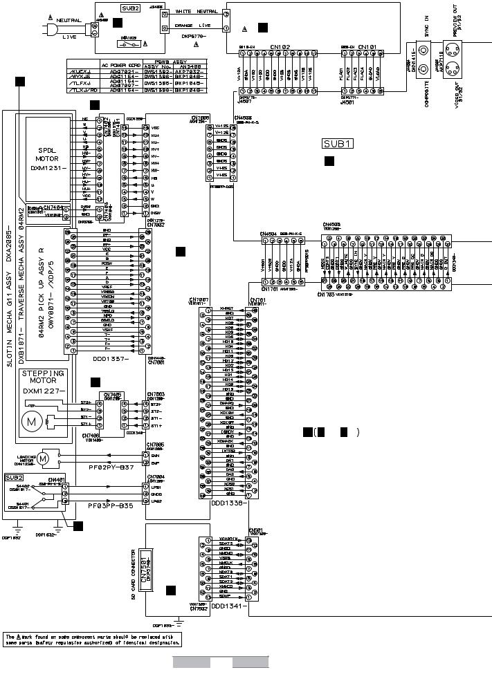
1 |
2 |
3.3 OVERALL WIRING DIAGRAM
A |
S PSWB ASSY |
U INSW ASSY (DWS1398)
C SPCN ASSY (DWX2629)
B
B DVPL ASSY (DWX2627)
C
D |
D STCN ASSY |
|
(DWX2628) |
E
E SLMB ASSY (DWS1395)
F SDCB ASSY (DWX2630)
F
24 |
DVJ-1000 |
|
|
|
|
3 |
4 |
T POWER SUPPLY ASSY (DWR1436)
GMJCB ASSY (DWG1633)
A A 1/8 - A 8/8
MAIN ASSY (DWG1630)
1 |
2 |
3 |
4 |
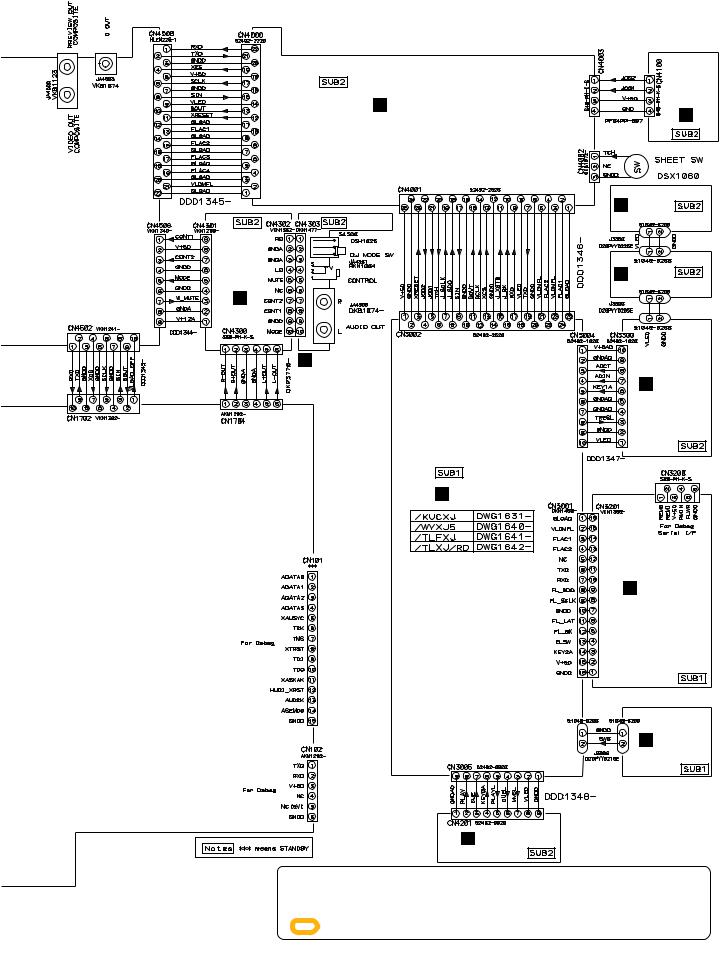
5
Q AUDB ASSY (DWG1638)
5
6 |
7 |
HJFLB ASSY (DWG1636)
R AJCB ASSY (DWG1639)
I DIPB ASSY
P KSWB ASSY (DWS1394)
8
A
J JOGB ASSY (DWG1637)
K LED2 ASSY |
B |
|
|
(DWG1635) |
|
L LED1 ASSY (DWG1634)
C
M SLDB ASSY (DWS1393)
D
N DFLB ASSY (DWG1632)
E
O RSWB ASSY (DWS1391)
÷ When ordering service parts, be sure to refer to "EXPLODED VIEWS and PARTS LIST" or |
F |
"PCB PARTS LIST". |
÷The > mark found on some component parts indicates the importance of the safety factor of the part. Therefore, when replacing, be sure to use parts of identical designation.
÷: The power supply is shown with the marked box.
|
|
|
|
|
25 |
|
DVJ-1000 |
7 |
|||
|
|
||||
6 |
|
|
|
8 |
|

1 |
2 |
3.4 MAIN ASSY (1/8)
A 1/8 MAIN ASSY (DWG1630)
A
Large size
SCH diagram
1/2
B
A 7/8
C 2/2
A 1/8 A 7/8
A 1/8
1/2 |
D
E
F
26 |
DVJ-1000 |
||
|
|
|
|
3 |
4 |
A 1/8
A 7/8, 8/8
1 |
2 |
3 |
4 |

5 6 7 8
|
A |
1/8 |
A |
7/8 |
A |
8/8 |
A |
1/8 |
|
|
|
|
A |
1/87 |
|||
A |
1/8 |
||||||||||||||||
|
|
|
|
||||||||||||||
|
|
|
|
|
|
|
|
|
|
|
|
|
|||||
|
|
|
|
|
|
|
|
|
|
|
|
|
|
|
|
|
|
A
B
1
C
CPU
|
A 4/8 |
|
D |
A 6/8 |
A 3/8 |
A 8/8
A 6/8
A 5/8
E
A 3/8
A 2/8
A 8/8
F
|
|
|
|
|
|
27 |
|
|
DVJ-1000 |
7 |
|||
|
|
|
||||
5 |
6 |
|
|
|
8 |
|
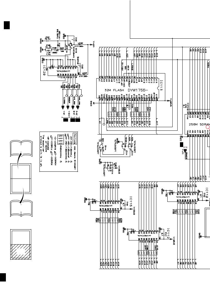
1 |
2 |
3 |
4 |
A
A 1/8 MAIN ASSY
B
C
1/8 A |
3/8 A 8/8 A |
Large size
SCH diagram
A 1/8
1/2
D
2/2
E
2/2 |
F
A 1/8
28 |
DVJ-1000 |
||
|
|
|
|
2
1 |
2 |
3 |
4 |

5 |
6 |
7 |
8 |
A
B
C
2
D
E
F
A 1/8
|
|
|
|
|
|
29 |
|
|
DVJ-1000 |
7 |
|||
|
|
|
||||
5 |
6 |
|
|
|
8 |
|
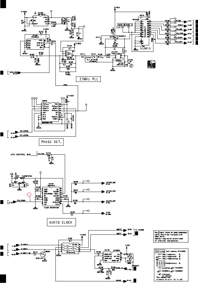
1 2
3.5 MAIN ASSY(2/8)
A A 2/8 MAIN ASSY (DWG1630)
B
A 8/8
C
A 8/8
D
3
A 2/8
E
A 7/8
A 8/8
F
A 2/8
30 |
DVJ-1000 |
||
|
|
|
|
3 |
4 |
A 4/8
A 2/8
A 3/8
A 8/8
A 2/8
A 5/8
Master Clock ADJ
A 8/8
A 7/8
 A 8/8
A 8/8
1 |
2 |
3 |
4 |
Loading...