


 Loading...
ORDER NO.
RRV2842
DVR-310-S
DVD RECORDER
DVR-310-S
DVR-210-S
THIS MANUAL IS APPLICABLE TO THE FOLLOWING MODEL(S) AND TYPE(S).
Model |
Type |
Power Requirement |
Regional restriction |
Remarks |
|
codes (Region No.) |
|||||
|
|
|
|
||
|
|
|
|
|
|
DVR-310-S |
KUXU/CA |
AC120V |
1 |
|
|
|
|
|
|
|
|
DVR-210-S |
KUXU/CA |
AC120V |
1 |
|
|
|
|
|
|
|
÷When servicing this model, some service procedures may reset the settings that customer set (*) to the factory default settings. Make sure to explain this to the customer.
(*) : Initial Setup (Clock Setting, Remote Control Set, Channel settings, Video Out settings, Audio In settings, Audio Out settings, Language settings)
Refer to the chapter 12 of the Operating Instructions for more details.
For details, refer to "Important symbols for good services" .
PIONEER CORPORATION 4-1, Meguro 1-chome, Meguro-ku, Tokyo 153-8654, Japan
PIONEER ELECTRONICS (USA) INC. P.O. Box 1760, Long Beach, CA 90801-1760, U.S.A.
PIONEER EUROPE NV Haven 1087, Keetberglaan 1, 9120 Melsele, Belgium
PIONEER ELECTRONICS ASIACENTRE PTE. LTD. 253 Alexandra Road, #04-01, Singapore 159936
 PIONEER CORPORATION 2003
T-ZZV SEPT. 2003 printed in Japan
1 |
2 |
3 |
4 |
SAFETY INFORMATION
A
This service manual is intended for qualified service technicians; it is not meant for the casual do-it-yourselfer. Qualified technicians have the necessary test equipment and tools, and have been trained to properly and safely repair complex products such as those covered by this manual.
Improperly performed repairs can adversely affect the safety and reliability of the product and may void the warranty. If you are not qualified to perform the repair of this product properly and safely, you should not risk trying to do so and refer the repair to a qualified service technician.
WARNING
BThis product contains lead in solder and certain electrical parts contain chemicals which are known to the state of California to cause cancer, birth defects or other reproductive harm.
Health & Safety Code Section 25249.6 – Proposition 65
NOTICE
(FOR CANADIAN MODEL ONLY)
Fuse symbols  (fast operating fuse) and/or
  (slow operating fuse) on PCB indicate that replacement parts must be of identical designation.
REMARQUE
(POUR MODÈLE CANADIEN SEULEMENT)
C Les symboles de fusible  (fusible de type rapide) et/ou
  (fusible de type lent) sur CCI indiquent que les pièces de remplacement doivent avoir la même désignation.
(FOR USA MODEL ONLY)
1. SAFETY PRECAUTIONS
The following check should be performed for the continued protection of the customer and service technician.
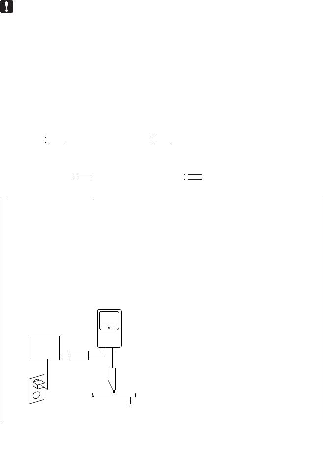
LEAKAGE CURRENT CHECK
Measure leakage current to a known earth ground (water pipe, conduit, etc.) by connecting a leakage
Dcurrent tester such as Simpson Model 229 - 2 or equivalent between the earth ground and all exposed metal parts of the appliance (input/output terminals, screwheads, metal overlays, control shaft, etc.). Plug the AC line cord of the appliance directly into a 120V AC 60 Hz outlet and turn the AC power switch on. Any current measured must not exceed 0.5 mA.
|
|
|
Reading should |
|
|
Leakage |
not be above |
|
|
0.5 mA |
|
|
|
current |
|
|
|
|
|
E |
Device |
tester |
|
|
under |
|
|
|
test |
|
|
|
Test all |
|
|
|
exposed metal |
|
|
|
surfaces |
|
|
|
Also test with |
|
|
|
plug reversed |
|
|
|
(Using AC adapter |
|
Earth |
|
plug as required) |
|
ground |
AC Leakage Test
ANY MEASUREMENTS NOT WITHIN THE LIMITS OUTLINED ABOVE ARE INDICATIVE OF A POTENTIAL SHOCK HAZARD AND MUST BE CORRECTED BEFORE RETURNING THE APPLIANCE TO THE CUSTOMER.
2. PRODUCT SAFETY NOTICE
Many electrical and mechanical parts in the appliance have special safety related characteristics. These are often not evident from visual inspection nor the protection afforded by them necessarily can be obtained by using replacement components rated for voltage, wattage, etc. Replacement parts which have these special safety characteristics are identified in this Service Manual.
Electrical components having such features are identified by marking with a  on the schematics and on the parts list in this Service Manual.
The use of a substitute replacement component which does not have the same safety characteristics as the PIONEER recommended replacement one, shown in the parts list in this Service Manual, may create shock, fire, or other hazards.
Product Safety is continuously under review and new instructions are issued from time to time. For the latest information, always consult the current PIONEER Service Manual. A subscription to, or additional copies of, PIONEER Service Manual may be obtained at a nominal charge from PIONEER.
F
|
|
|
|
|
|
|
2 |
|
DVR-310 |
-S |
|
|
|
1 |
2 |
|
|
|
3 |
4 |
5 |
6 |
7 |
8 |
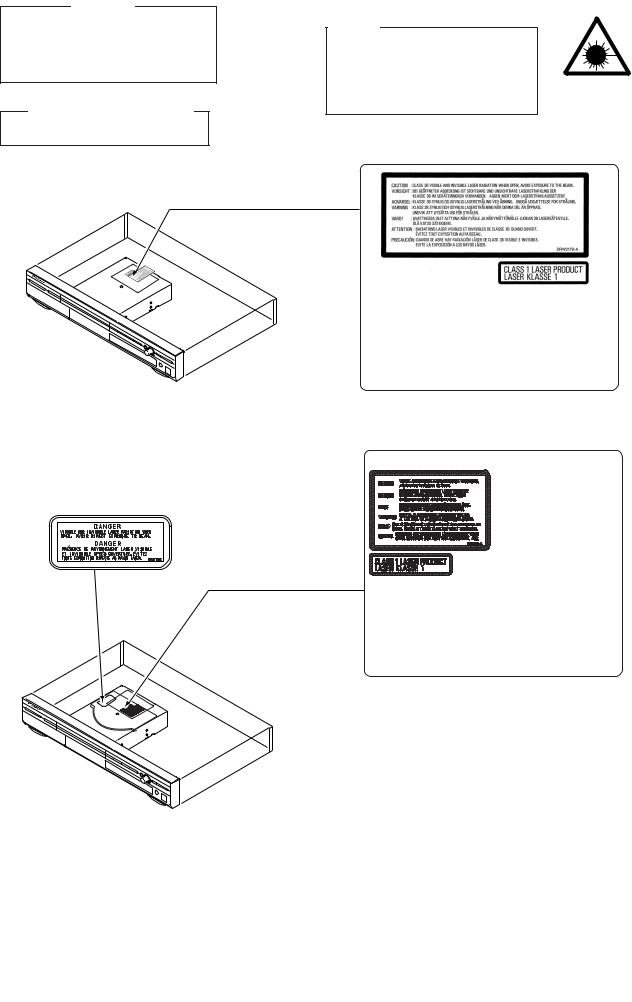
IMPORTANT
THIS PIONEER APPARATUS CONTAINS LASER OF CLASS 1.
SERVICING OPERATION OF THE APPARATUS SHOULD BE DONE BY A SPECIALLY INSTRUCTED PERSON.
LASER DIODE CHARACTERISTICS
MAXIMUM OUTPUT POWER : 50 mw WAVELENGTH : 658 nm
WARNING!
DEVICE INCLUDES LASER DIODE WHICH EMITS INVISIBLE INFRARED RADIATION WHICH IS DANGEROUS TO EYES. THERE IS A WARNING SIGN ACCORDING TO PICTURE 1 INSIDE THE DEVICE CLOSE TO THE LASER DIODE.
A
LASER
Picture 1 Warning sign for laser radiation

 LABEL CHECK
B
DRW2179
C
*Some models have different caution labels like the figure below .
D
DRW2080
DRW2152
|
Additional Laser Caution |
|
E |
|
|
||
|
|
|
|
1. The ON/OFF(ON:low level,OFF:high level) status of the |
|||
CLAMP signals for detecting the loading state are detected |
|
||
by the drive CPUs, and the design prevents laser diode |
|
||
oscillation when the CLAMP signal turns OFF. |
|
||
In normal operation, if no disc is clamped, the laser diode |
|
||
oscillation is disabled. |
|
||
However, the interlock does not always operate in the test |
|
||
mode. |
|
||
2. When the cover is opened, close viewing of the objective |
|
||
lens with the naked eye will cause exposure to a Class 3A |
|
||
laser beam. |
|
||
|
|
|
F |
|
|
|
|
|
|
|
|
|
|
|
|
|
DVR |
-310-S |
7 |
3 |
|
5 |
6 |
|
|
|
8 |
|

1 |
2 |
3 |
4 |
[ Important symbols for good services ]
In this manual, the symbols shown-below indicate that adjustments, settings or cleaning should be made securely.
When you find the procedures bearing any of the symbols, be sure to fulfill them:
A
1. Product safety
You should conform to the regulations governing the product (safety, radio and noise, and other regulations), and should keep the safety during servicing by following the safety instructions described in this manual.
2. Adjustments
To keep the original performances of the product, optimum adjustments or specification confirmation is indispensable.
In accordance with the procedures or instructions described in this manual, adjustments should be performed.
|
3. Cleaning |
B |
For optical pickups, tape-deck heads, lenses and mirrors used in projection monitors, and other parts requiring cleaning, |
|
proper cleaning should be performed to restore their performances. |
4. Shipping mode and shipping screws
To protect the product from damages or failures that may be caused during transit, the shipping mode should be set or the shipping screws should be installed before shipping out in accordance with this manual, if necessary.
5. Lubricants, glues, and replacement parts
Appropriately applying grease or glue can maintain the product performances. But improper lubrication or applying
glue may lead to failures or troubles in the product. By following the instructions in this manual, be sure to apply the

 prescribed grease or glue to proper portions by the appropriate amount.For replacement parts or tools, the prescribed ones should be used.
C
D
E
F
|
|
|
|
|
|
|
4 |
|
DVR-310 |
-S |
|
|
|
1 |
2 |
|
|
|
3 |
4 |

5 6 7 8
CONTENTS
SAFETY INFORMATION...................................................................................................................................... |
2 |
1. SPECIFICATIONS ............................................................................................................................................. |
6 |
2. EXPLODED VIEWS AND PARTS LIST............................................................................................................. |
8 |
2.1 PACKING .................................................................................................................................................... |
8 |
2.2 EXTERIOR ............................................................................................................................................... |
10 |
2.3 FRONT PANEL ......................................................................................................................................... |
12 |
3. BLOCK DIAGRAM AND SCHEMATIC DIAGRAM .......................................................................................... |
14 |
3.1.1 OVERALL BLOCK DIAGRAM ............................................................................................................... |
14 |
3.1.2 TUJB ASSY BLOCK DIAGRAM ............................................................................................................ |
16 |
3.1.3 MAIN ASSY BLOCK DIAGRAM ............................................................................................................ |
18 |
3.1.4 POWER BLOCK DIAGRAM .................................................................................................................. |
20 |
3.2 ATAB ASSY and OVERALL WIRING DIAGRAM ...................................................................................... |
22 |
3.3 TUMJ(1/2), FRJB and DVJB ASSYS ........................................................................................................ |
24 |
3.4 TUMJ ASSY(2/2) ...................................................................................................................................... |
26 |
3.5 MAIN ASSY(1/5)....................................................................................................................................... |
28 |
3.6 MAIN ASSY(2/5)....................................................................................................................................... |
30 |
3.7 MAIN ASSY(3/5)....................................................................................................................................... |
32 |
3.8 MAIN ASSY(4/5)....................................................................................................................................... |
34 |
3.9 MAIN ASSY(5/5)....................................................................................................................................... |
36 |
3.10 MHLP ASSY ........................................................................................................................................... |
38 |
3.11 FLKY ASSY ............................................................................................................................................ |
40 |
3.12 POWER SUPPLY UNIT .......................................................................................................................... |
42 |
3.13 WAVE FORMS........................................................................................................................................ |
43 |
4. PCB CONNECTION DIAGRAM ...................................................................................................................... |
45 |
4.1 ATAB ASSY............................................................................................................................................... |
45 |
4.2 TUMJ, FRJB and DVJB ASSYS ............................................................................................................... |
46 |
4.3 MAIN and MHLP ASYS ............................................................................................................................ |
50 |
4.4 POWER SUPPLY UNIT ............................................................................................................................ |
54 |
4.5 FLKY ASSY .............................................................................................................................................. |
56 |
5. PCB PARTS LIST ............................................................................................................................................ |
57 |
6. ADJUSTMENT ................................................................................................................................................ |
61 |
6.1 TUMJ ASSY ADJUSTMENT..................................................................................................................... |
61 |
6.2 MAIN ASSY ADJUSTMENT ..................................................................................................................... |
62 |
7. GENERAL INFORMATION ............................................................................................................................. |
63 |
7.1 DIAGNOSIS.............................................................................................................................................. |
63 |
7.1.1 CPRM ID NUMBER AND DATA SETTING ............................................................................................ |
63 |
7.1.2 SERVICE MODE ................................................................................................................................... |
65 |
7.1.3 DV DEBUG MODE ................................................................................................................................ |
73 |
7.1.4 ERROR RATE MEASUREMENT........................................................................................................... |
76 |
7.1.5 VIDEO ADJUSTMENT FOR SPECIFIC AREA...................................................................................... |
78 |
7.1.6 SETUP SEQUENCE.............................................................................................................................. |
82 |
7.1.7 DISASSEMBLY...................................................................................................................................... |
83 |
7.2 IC .............................................................................................................................................................. |
86 |
7.3 OUTLINE OF THE PRODUCT ............................................................................................................... |
113 |
7.4 DISC/CONTENT FORMAT ..................................................................................................................... |
116 |
7.5 CLEANING ............................................................................................................................................. |
118 |
8. PANEL FACILITIES ....................................................................................................................................... |
119 |
A
B
C
D
E
F
|
|
|
|
|
|
|
|
|
DVR |
-310-S |
7 |
5 |
|
5 |
6 |
|
|
|
8 |
|

|
1 |
|
2 |
|
1. SPECIFICATIONS |
||
A |
General |
|
|
System.......................... |
DVD-Video, DVD-R/RW, Video-CD, |
||
|
CD, CD-R/RW (WMA, MP3, JPEG. CD-DA) |
||
|
Power requirements.......................................... |
|
120 V, 60 Hz |
|
Power consumption....................................................... |
|
26 W |
|
Power consumption in standby mode |
............0.44 W (FL off) |
|
|
Weight ........................................................ |
|
9 lb 8 oz / 4.3 kg |
|
Dimensions........................... |
420 (W) x 69 (H) x 341 (D) mm |
|
|
Operating temperature.................................... |
|
+5°C to +35°C |
|
Operating humidity.................. |
5% to 85% (no condensation) |
|
|
TV format..................................................................... |
|
NTSC |
B |
Recording |
|
|
Recording format |
|
DVD Video Recording |
|
|
|
||
DVD-VIDEO
Recordable discs
DVD-RW (DVD Re-recordable disc)
DVD-R (DVD Recordable disc)
Video recording format
|
Sampling frequency................................................. |
13.5MHz |
|
Compression format.................................................... |
MPEG |
|
Audio recording format |
|
C |
Sampling frequency .................................................... |
48kHz |
|
Compression format.................. |
Dolby Digital or Linear PCM |
|
|
(uncompressed) |
|
Recording time |
|
|
Fine (FINE)..................................................... |
Approx. 1 hour |
|
Standard Play (SP)....................................... |
Approx. 2 hours |
|
Long Play (LP).............................................. |
Approx. 4 hours |
|
Extended Play (EP)...................................... |
Approx. 6 hours |
|
Manual Mode (MN)................................... |
Approx. 1–6 hours |
|
Tuner |
|
|
|
D |
Receivable channels |
|
||
VHF |
|
2–13ch |
||
|
|
|||
|
UHF.......................................................................... |
|
14–69ch |
|
|
CATV................................................................... |
|
C1–C125ch |
|
|
Timer |
|
|
|
|
Programs.............................................. |
1 month/32 |
||
|
programs |
|
|
|
|
Clock.............................. |
Quartz lock (12-hour digital display) |
||
|
Power off memory......... |
Approx. 5 years (after manufacture) |
||
E |
Input/Output |
|
|
|
VHF/UHF antenna input/output terminal |
VHF/UHF set |
|||
|
||||
|
|
75 Ω (F-shape connector) |
||
|
Video input...................................... |
Input 1, 3 (rear), 2 (front) |
||
|
Input level......................................................... |
|
1 Vp-p (75 Ω ) |
|
|
Jacks....................................................................... |
|
RCA jack |
|
|
Video output.......................................................... |
|
Output 1,2 |
|
F
3 |
4 |
Output level...................................................... |
1 Vp-p (75 Ω |
) |
Jacks....................................................................... |
RCA jack |
|
S-Video input.................................. |
Input 1, 3 (rear), 2 (front) |
|
Y (luminance) - Input level................................ |
1 Vp-p (75 Ω |
) |
C (color) - Input level................................. |
286 mVp-p (75 Ω |
) |
Jacks............................................................... |
4 pin mini DIN |
|
S-Video output....................................................... |
Output 1,2 |
|
Y (luminance) - Output level............................. |
1 Vp-p (75 Ω |
) |
C (color) - Output level.............................. |
286 mVp-p (75 Ω |
) |
Jacks............................................................... |
4 pin mini DIN |
|
Component video output |
|
|
Output level............................................... |
Y: 1.0 Vp-p (75 Ω |
) |
|
PB, PR: 0.7 Vp-p (75 Ω |
) |
Jacks..................................................................... |
RCA jacks |
|
Audio input............................... |
Input 1, 3 (rear), 2 (front) L/R |
|
Input level |
|
|
During audio input....................................................... |
2V rms |
|
(Input impedance: more than 22 kΩ |
) |
|
Jacks..................................................................... |
RCA jacks |
|
Audio output.................................................... |
Output 1,2 L/R |
|
During audio output.................................................... |
2V rms |
|
(Output impedance: less than 1.5 kΩ |
) |
|
Jacks..................................................................... |
RCA jacks |
|
Control input............................................................. |
Mini jack |
|
DV input/output............................................................... |
4 pin |
|
|
(i.LINK/IEEE 1394 standard) |
|
Supplied accessories |
|
|
Remote control..................................................................... |
|
1 |
Dry cell batteries (AA/R6P).................................................. |
|
2 |
Audio / Video cable (red/white/yellow)................................. |
1 |
|
RF antenna cable................................................................. |
|
1 |
Power cable......................................................................... |
|
1 |
Operating Instructions.......................................................... |
|
1 |
Warranty card....................................................................... |
|
1 |
Note: The specifications and design of this product are subject to change without notice, due to improvement.
|
|
|
|
|
|
|
6 |
|
DVR-310 |
-S |
|
|
|
1 |
2 |
|
|
|
3 |
4 |
5 |
6 |
7 |
8 |
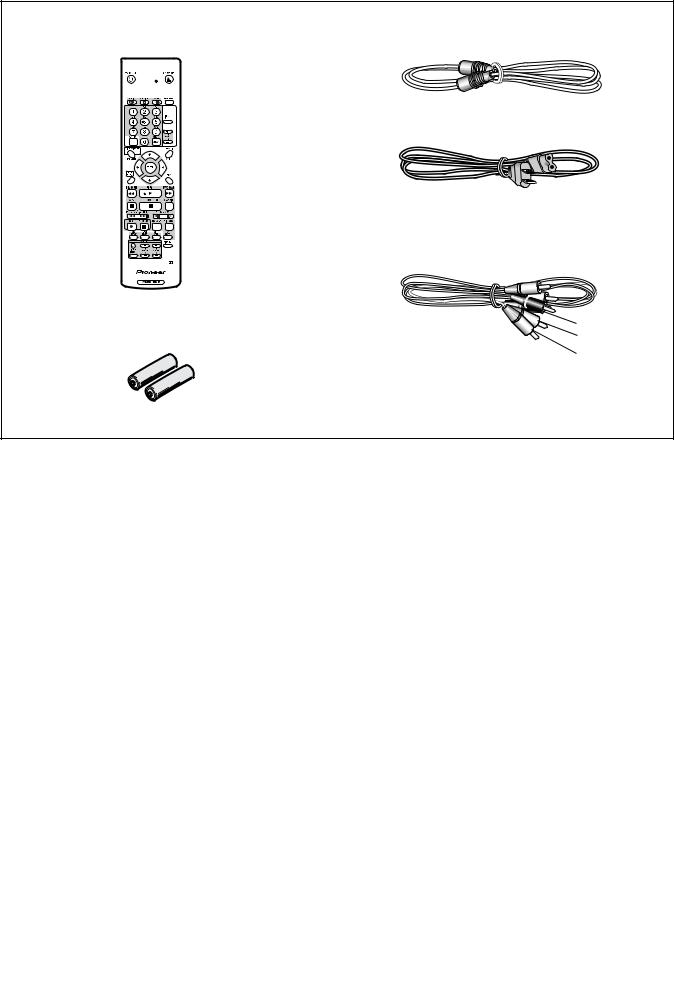
 Accessories
• Remote control × 1 |
• RF antenna cable × 1 |
A |
(VXX2882) |
(VDE1025) |
|
• Power cable × 1 (ADG7021)
B
• Audio / Video cable(L=1.5m) × 1 (red/white/yellow)
(VDE1077)
• Dry cell batteries × 2 |
Red |
(AA/R6P) |
White |
|
Yellow |
C
D
E
F
|
|
|
|
|
|
|
|
|
DVR |
-310-S |
7 |
7 |
|
5 |
6 |
|
|
|
8 |
|

1 2 3 4
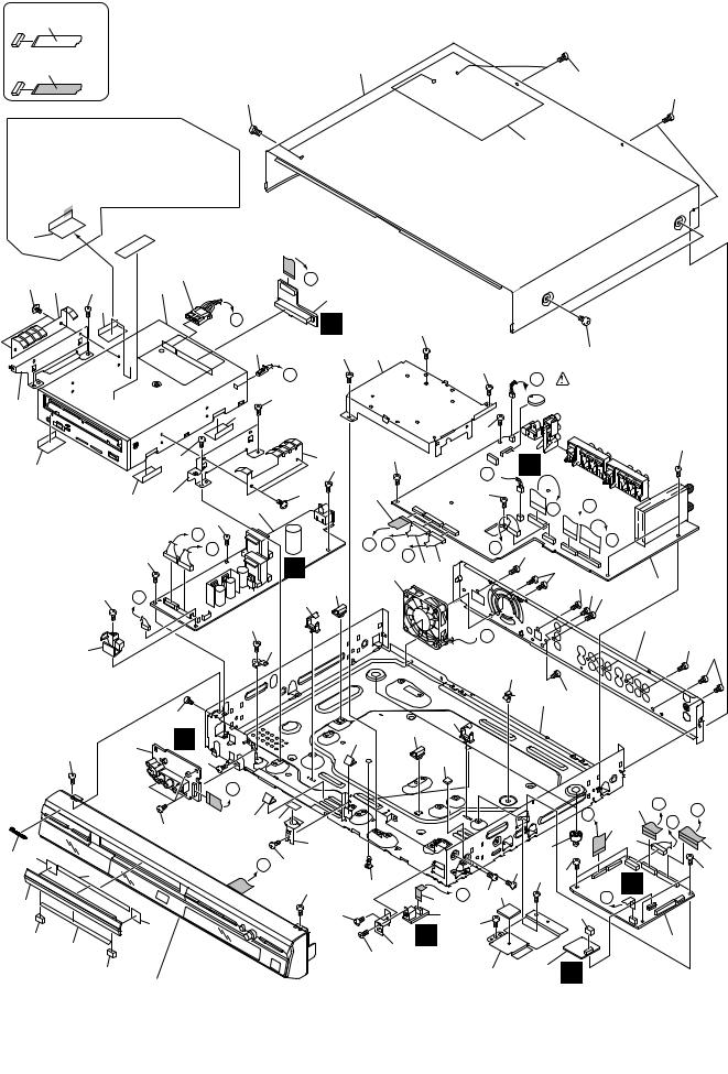
2. EXPLODED VIEWS AND PARTS LIST
A
NOTES: Parts marked by "NSP" are generally unavailable because they are not in our Master Spare Parts List. |
|
The |
mark found on some component parts indicates the importance of the safety factor of the part. |
Therefore, when replacing, be sure to use parts of identical designation.  Screws adjacent to
  mark on product are used for disassembly.
 For the applying amount of lubricants or glue, follow the instructions in this manual. (In the case of no amount instructions, apply as you think it appropriate.)
2.1 PACKING
10
9
8
6
B
11
7
13 |
11 |
C
5
12
4
D
14
15
E
F |
16 |
|
|
|
|
|
|
|
|
8 |
|
DVR-310 |
-S |
|
|
|
1 |
2 |
|
|
|
3 |
4 |
2
3
1

5 6 7 8
(1)PACKING parts List
Mark No. |
Description |
Part No. |
Mark No. |
Description |
Part No. |
> 1 |
Power Cable |
ADG7021 |
NSP 10 |
Warranty Card |
ARY7045 |
2 |
Audio/Video Cable |
VDE1077 |
|
|
A |
|
|
|
|||
3 |
RF Antenna Cable |
VDE1025 |
11 |
Polyethylene Bag |
VHL1051 |
4 |
Remote Control |
VXX2882 |
12 |
Mirror Sheet |
VHL1006 |
5 |
Battery Cover |
AZA7424 |
13 |
Accessory Case |
VHC1112 |
|
|
|
14 |
Front Pad |
VHA1346 |
NSP 6 |
Dry Cell Batteries (R6P,AA) |
VEM1010 |
15 |
Rear Pad |
VHA1347 |
7 |
Operating Instructions |
VRB1314 |
|
|
|
|
(English) |
|
16 |
Packing Case |
See Contrast table(2) |
NSP 8 |
Information Card |
VRR1048 |
|
|
|
NSP 9 |
Card |
VRY1132 |
|
|
|
B
(2) CONTRAST TABLE
DVR-310-S/KUXU/CA and DVR-210-S/KUXU/CA are constructed the same except for the following :
Mark |
No. |
Symbol and Description |
DVR-310-S/ |
DVR-210-S/ |
|
KUXU/CA |
KUXU/CA |
||||
|
|
|
|||
|
|
|
|
|
|
|
16 |
Packing Case |
VHG2411 |
VHG2454 |
C
D
E
F
|
|
|
|
|
|
|
|
|
DVR |
-310-S |
7 |
9 |
|
5 |
6 |
|
|
|
8 |
|
1 |
2 |
3 |
4 |
2.2 EXTERIOR
NON-CONTACT
A SIDE
CONTACT SIDE
52
Bond Lock process
(Use GYA1011 or GYL1005)
Paste the bond both to the aluminum tape and the side chassis of the DRIVE Assy.(  part)
part)
The paste point is only this aluminum tape.
B
31 |
|
|
Acetate Tape |
|
|
(Taping for No.14 FFC) |
|
|
|
|
|
48 |
|
|
16 |
22 |
49 |
7 |
|
|
|
31 |
|
|
|
|
K |
|
|
|
18 |
M
49
C |
37 |
|
31 |
31 |
49 |
|
|
||
31 |
36 |
|
6 |
||
|
||
|
49 |
33
C
1 |
|
A |
49 |
49 |
38 |
22 49
49
48 15
|
|
|
I |
H |
I |
|
|
|
49 |
J |
J |
||
|
|
G |
|
|||
|
|
|
|
|||
|
|
|
|
8 |
11 10 |
|
D |
49 |
K |
|
21 |
|
|
|
25 |
|
|
|||
|
|
|
|
|
|
|
|
|
|
|
49 |
|
|
|
41 |
|
|
35 |
|
|
|
|
|
|
|
|
|
|
49 |
|
|
|
25 |
|
3 |
C |
|
|
27 |
21 |
|
|
|
|
|||
|
|
|
|
|
|
|
|
49 |
|
49 |
|
|
26 |
|
|
|
|
|
||
E |
|
|
H |
|
|
|
|
|
49 |
28 |
29 |
|
|
|
|
|
|
|
||
|
|
|
|
|
|
|
|
43 |
|
|
39 |
|
|
42 |
|
|
A 49 |
|
|
|
|
45 |
|
|
|
|
|
|
|
|
49 |
20 |
|
|
|
|
|
|
53 |
||
47 |
|
|
|
|
||
|
|
49 |
|
9 |
||
|
|
43 |
|
|
||
|
|
|
|
|
H |
|
|
46 |
|
|
|
|
|
|
44 |
|
|
|
56 |
54 |
F |
46 |
|
|
|
|
|
Refer to "2.3 FRONT PANEL".
49
49
55
52
49
N
 Lithium Battery
49
49
M  B
B
49
A  E
E
F |
G |
|
51 |
|
|
|
50 |
|
|
5049 50 |
2 |
|
|
32 |
 N
N
50 49
24
34 49
|
|
|
13 |
E |
G |
|
|
|
C |
|
|
|
|
|
|
F |
|
|
|
|
14 |
|
|
|
19 |
|
17 |
|
|
|
|
|
|
12 |
|
|
49 |
|
|
|
|
|
49 |
|
|
49 |
|
|
49 |
D |
|
||
|
|
|
|||
B 49 23 |
|
|
|
|
|
|
|
B |
|
|
|
49 |
|
30 |
|
|
|
|
|
|
|
|
|
|
|
|
|
|
4 |
40 |
5 |
E |
|
|
|
|
|
|
|
|
|
|
|
|
|
|
|
10 |
|
DVR-310 |
-S |
|
|
|
1 |
2 |
|
|
|
3 |
4 |
|
5 |
6 |
(1)EXTERIOR parts List |
|
|
Mark No. |
Description |
Part No. |
1 |
ATAB ASSY |
VWV1968 |
2 |
TUMJ ASSY |
VWV1960 |
3 |
FRJB ASSY |
VWV1964 |
4 |
MAIN ASSY |
VWV1952 |
5 |
MHLP ASSY |
VWV1991 |
> 6 |
POWER SUPPLY UNIT |
VWR1373 |
7 |
DRIVE ASSY R6 |
VXX2898 |
8 |
DC FAN Motor |
VXM1109 |
9 |
DVJB ASSY |
VWV1966 |
10 |
Connector Assy |
PF08EE-D20 |
11 |
Connector Assy |
PF13PP-D20 |
12 |
Flexible Cable (32P) |
VDA1975 |
13 |
Flexible Cable (21P) |
VDA1976 |
14 |
Flexible Cable (40P) |
VDA1977 |
15 |
Flexible Cable (15P) |
VDA1978 |
16 |
Housing Assy (4P) |
VKP2313 |
17 |
Housing Assy (8P) |
VKP2314 |
18 |
Housing Assy (2P) |
VKP2315 |
19 |
Leg Assy |
AEC7113 |
NSP 20 |
PCB Holder |
PNW1706 |
NSP 21 |
P. Plate Holder |
PNY-405 |
22 |
Earth Plate |
VBK1148 |
23 |
Radiation Sheet |
VEB1360 |
24 |
Card Spacer |
VEC1708 |
NSP 25 |
Clamp |
VEC2362 |
26 |
Heatsink Cushion |
VEC2363 |
27 |
Gasket A |
VEC2382 |
28 |
Gasket B |
VEC2393 |
29 |
Gasket Sheet |
VEC2394 |
|
7 |
8 |
Mark No. |
Description |
Part No. |
30 |
M Cushion A |
VEC2398 |
31 |
Aluminum tape |
VEF1056 |
32 |
Rear Panel |
See Contrast table(2) |
33 |
Bonnet Case |
VXX2897 |
NSP 34 |
Base Chassis |
VNB1039 |
35 |
PCB Base |
VNE2278 |
NSP 36 |
Writer Stay R |
VNE2318 |
NSP 37 |
Writer Stay L |
VNE2319 |
NSP 38 |
HDD Stay |
VNE2320 |
NSP 39 |
Bonnet Angle |
VNE2321 |
NSP 40 |
Heatsink |
VNH1070 |
41 |
Cable Holder |
VNK5330 |
42 |
Pioneer Name Plate |
VAM1136 |
43 |
Tray Sheet A |
VEC2346 |
44 |
Tray Sheet B |
VEC2358 |
45 |
Tray Sheet C |
VEC2395 |
46 |
Tray Sheet D |
VEC2396 |
47 |
Tray Panel Assy |
See Contrast table(2) |
48 |
Screw |
AMZ30P060FMC |
49 |
Screw |
BBZ30P060FMC |
50 |
Screw |
BPZ30P080FZK |
51 |
Screw |
PPZ30P080FMC |
52 |
Screw |
BCZ40P060FN |
53 |
Flexible Cable (7P) |
VDA1979 |
NSP 54 |
DV Angle |
VNE2322 |
55 |
Bonnet Label |
VRW1985 |
56 |
Screw |
VBA108 |
(2) CONTRAST TABLE
DVR-310-S/KUXU/CA and DVR-210-S/KUXU/CA are constructed the same except for the following :
Mark |
No. |
Symbol and Description |
DVR-310-S/ |
DVR-210-S/ |
|
KUXU/CA |
KUXU/CA |
||||
|
|
|
|||
|
|
|
|
|
|
|
32 |
Rear Panel |
VNA2608 |
VNA2683 |
|
|
47 |
Tray Panel Assy |
VXA2602 |
VXA2628 |
A
B
C
D
E
F
|
|
|
|
|
|
|
|
|
DVR |
-310-S |
7 |
11 |
|
5 |
6 |
|
|
|
8 |
|
1 |
2 |
3 |
4 |
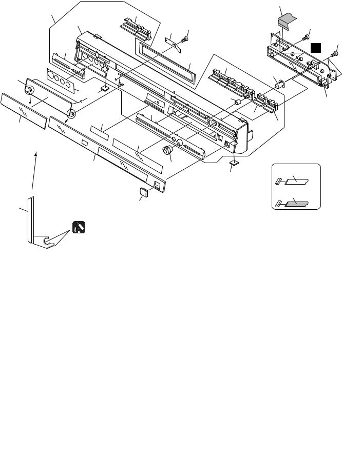
2.3 FRONT PANEL
A
|
|
|
|
2 |
15 |
|
20 |
|
|
16 |
|
|
24 |
24 |
|
|
4 |
||
|
|
|
|
|
|
|
|
|
24 |
18 |
|
|
|
F |
B |
|
|
6 |
|
|
|
|
19 |
|
11 |
|
|
|
13 |
|
|
|
|
|
9 |
5 |
|
|
|
3 |
|
23 |
1 |
|
|
|
|
|
|
|
|
17 |
|
22 |
|
14 |
|
|
|
8 |
|
|
21 |
|
|
|
|
||
|
|
|
|
|
|
|
10 |
|
|
C |
|
|
|
|
|
7 |
12 |
|
NON-CONTACT |
|
|
|
|
|
|
|
|
5 |
SIDE |
|
|
|
|
CONTACT SIDE |
11 |
|
25 |
|
|
|
|
|
|
|
Daifree |
|
|
|
|
GEM1036 |
|
|
|
|
D |
|
|
|
|
E
F
|
|
|
|
|
|
|
12 |
|
DVR-310 |
-S |
|
|
|
1 |
2 |
|
|
|
3 |
4 |

|
5 |
6 |
(1)FRONT PANEL parts List |
|
|
Mark No. |
Description |
Part No. |
1 |
FLKY ASSY |
VWG2443 |
2 |
Flexible Cable (19P) |
VDA1974 |
3 |
Rubber Sheet |
AEB7054 |
4 |
Door Spring |
VBK1144 |
5 |
Rubber Foot |
VEB1349 |
6 |
Drive Sheet |
VEC2345 |
7 |
FL Lens |
See Contrast table(2) |
8 |
Door Lens |
See Contrast table(2) |
9 |
Jack Sheet |
VEC2381 |
10 |
FL Filter (for DVR-310-S) |
See Contrast table(2) |
10 |
Mirror Filter (for DVR-210-S) |
See Contrast table(2) |
11 |
Jack Door |
VNK5309 |
12 |
JOG Dial L |
VNK5324 |
13 |
JOG Base |
VNK5317 |
|
7 |
8 |
|
|
Mark No. |
Description |
Part No. |
|
|
14 |
Hologram Label |
VRW1962 |
A |
|
15 |
Flont Panel Assy |
See Contrast table(2) |
||
|
||||
NSP 16 |
Front Panel |
See Contrast table(2) |
|
|
17 |
Front Cover R |
See Contrast table(2) |
|
|
18 |
Front Cover L |
See Contrast table(2) |
|
|
19 |
Main Key S |
VNK5312 |
|
|
20 |
Power Key S |
VNK5313 |
|
|
21 |
Rec Key |
VNK5314 |
|
|
22 |
Stop Key S |
VNK5315 |
|
|
23 |
Function Cover |
VNK5318 |
B |
|
24 |
Screw |
BPZ30P080FZK |
||
|
||||
25 |
DV Cover |
See Contrast table(2) |
|
(2) CONTRAST TABLE
DVR-310-S/KUXU/CA and DVR-210-S/KUXU/CA are constructed the same except for the following :
Mark |
No. |
Symbol and Description |
DVR-310-S/ |
DVR-210-S/ |
|
KUXU/CA |
KUXU/CA |
|
|||
|
|
|
|
||
|
|
|
|
|
|
|
7 |
FL Lens |
VEC2352 |
VEC2402 |
|
|
8 |
Door Lens |
VEC2374 |
VEC2375 |
C |
|
10 |
FL Filter (for DVR-310-S) |
VEC2354 |
Not used |
|
|
10 |
Mirror Filter (for DVR-210-S) |
Not used |
VEC2347 |
|
|
15 |
Front Panel Assy |
VXA2621 |
VXA2637 |
|
NSP |
16 |
Front Panel |
VNK5363 |
VNK5428 |
|
|
17 |
Front Cover R |
VNK5360 |
VNK5430 |
|
|
18 |
Front Cover L |
VNK5358 |
VNK5431 |
|
|
25 |
DV Cover |
VNK5355 |
VNK5365 |
|
D
E
F
|
|
|
|
|
|
|
|
|
DVR |
-310-S |
7 |
13 |
|
5 |
6 |
|
|
|
8 |
|

1 |
2 |
3 |
4 |
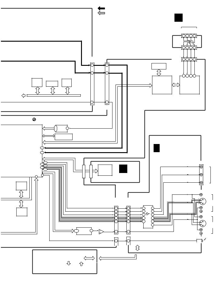
3. BLOCK DIAGRAM AND SCHEMATIC DIAGRAM
3.1 BLOCK DIAGRAM
A |
3.1.1 OVERALL BLOCK DIAGRAM |
|
|
|
|
|
|
|
|
|
|
|||||||||||
|
ANT |
U3001 VXF1022 |
|
|
|
|
|
|
Y/Comp |
|
|
|
|
|
|
|
|
|||||
|
TV FRONT-END |
|
|
|
|
|
|
|
|
|
|
|
|
|
|
|||||||
|
|
|
|
|
|
|
|
|
|
|
|
|
|
|
|
|||||||
|
|
RF IN |
|
|
|
|
|
|
|
|
|
|
Selector |
|
|
|
|
|
|
|
|
|
|
|
AOUT VOUT |
|
|
|
|
|
|
IC3301 |
|
|
|
|
|
|
|
|
|||||
|
|
RF |
|
|
|
|
|
|
LA73030 |
|
|
|
|
|
|
|
|
|||||
|
|
OUT |
16 |
|
19 |
|
|
|
|
|
|
|
|
|
|
|
|
|
|
|
|
|
|
|
|
|
|
|
|
|
|
|
|
UVV |
32 |
|
|
|
|
|
|
|
|
|
|
|
|
|
|
|
|
|
|
|
|
|
34 |
|
|
|
|
|
|
|
|
|
|
|
|
|
|
|
|
|
|
|
|
|
|
2V |
|
|
|
|
|
|
|
|
|
|
|
|
|
|
|
|
|
|
|
|
|
|
36 |
|
|
|
|
|
|
|
|
|
|
|
|
|
|
|
|
|
|
|
|
|
|
1V |
|
|
|
|
|
|
|
|
|
|
|
|
|
|
|
|
|
|
|
|
|
|
1 |
|
|
|
|
|
|
|
|
|
|
|
|
|
|
|
|
|
|
|
|
|
|
3V |
|
|
|
|
|
|
|
|
|
|
|
|
|
|
|
|
|
|
|
|
|
|
3 |
|
|
V/Y |
|
|
|
|
|
|
V/Y |
|
|
|
|
|
|
|
|
|
|
|
|
|
|
|
LPF |
|
|
|
|
||||
|
|
|
|
|
|
|
|
|
|
|
|
|
|
|
24 |
|
|
|
|
|
||
|
|
|
|
|
|
|
|
|
|
|
3Y |
15 |
|
|
|
|
|
|
|
|
|
|
|
|
|
|
|
|
|
|
|
|
|
|
|
|
|
|
|
|
|
|
|
|
|
B |
|
|
|
|
|
|
|
|
|
|
1Y |
17 |
|
|
|
|
|
|
|
|
|
|
|
|
|
|
|
|
|
|
|
|
|
|
|
|
|
|
|
|
|
|
|
||
|
|
|
|
|
|
|
|
|
|
2Y |
19 |
|
|
|
|
|
|
|
|
|
|
|
|
|
|
|
|
|
|
|
|
|
|
|
|
|
|
|
|
|
|
|
|
||
|
|
|
|
|
|
|
|
|
|
|
|
|
|
|
|
|
|
|
|
|
|
|
|
C |
CN1301 |
CN3002 |
|
3C |
5 |
|
|
|
|
|
|
|
|
|
|
||||||
|
|
1C |
|
|
C |
|
|
|
|
|
|
C |
||||||||||
|
|
|
(15P) |
|
|
(15P) |
|
7 |
|
|
26 |
LPF |
|
|
|
|
|
|||||
|
|
|
CIN2 |
|
2C |
|
|
|
|
|
|
|
||||||||||
|
|
|
14 |
2 |
|
|
9 |
|
|
|
|
|
|
|
|
|
|
|||||
|
FRJB |
|
|
|
|
|
|
|
|
|
|
|
|
|
|
|
|
|
|
|
|
|
|
ASSY |
|
|
|
|
|
|
|
|
|
|
|
|
|
|
|
|
|
|
|
|
|
|
|
JA1301 |
|
12 |
YIN2 |
4 |
|
|
|
|
|
|
|
|
|
|
|
|
|
|
||
|
|
Y |
|
|
|
|
|
|
|
|
|
|
Audio Selector with Electirc ATT |
|
||||||||
|
|
|
|
|
|
|
|
|
|
|
|
|
|
|
|
|
||||||
|
Y/C |
|
|
|
|
|
|
|
|
|
ATT WIDEBAND |
SPECTRAL |
|
|
|
|||||||
|
C |
|
|
|
|
|
|
|
|
|
|
|
|
IC2801 |
|
|
|
|||||
|
|
|
|
|
|
|
|
|
|
|
|
|
|
|
|
|
||||||
|
|
JA1302 |
|
|
|
|
|
|
|
|
IC3105 CXA2064M |
|
|
|
|
LC75342M |
|
|
|
|||
|
|
|
|
|
|
|
|
|
|
MPX Audio MPX L 23 UVL |
|
|
|
|
|
|
|
|
||||
|
VIDEO |
|
|
|
|
|
|
|
|
|
7 |
LPF |
|
|
|
|
|
|
|
|||
|
L |
|
|
|
10 |
VIN2 |
6 |
|
|
|
IN |
Decoder |
OUT |
|
|
|
11 |
|
|
|
|
|
|
|
|
|
|
|
|
|
|
|
|
|
|
|
|
|
|
13 |
|
|
|
|
|
C |
|
|
|
|
|
|
|
|
|
|
|
|
|
|
|
|
|
|
|
L |
|
|
R |
|
|
|
6 |
LIN2 |
10 |
|
|
|
|
|
|
|
|
|
14 |
5 |
|
|
|||
|
|
|
|
|
|
|
|
|
|
|
|
|
|
|
||||||||
|
INPUT3 |
|
|
|
|
|
|
|
|
|
|
|
|
|
|
|
12 |
|
|
|
|
|
|
|
|
|
|
|
|
|
|
|
|
|
|
|
|
LIN2 |
|
|
|
|
|
|
|
|
INPUT1 |
JA2832 |
|
|
|
|
|
|
|
|
|
|
|
LIN1 |
|
|
|
|
|
|
||
|
|
|
VIN1 |
|
|
|
|
|
|
|
LIN3 |
|
|
|
|
|
|
|||||
|
VIDEO |
|
|
|
|
|
|
|
|
|
|
|
|
|
|
|
|
|
||||
|
|
|
|
|
|
|
|
|
|
|
|
|
|
|
|
|
|
|
|
|
|
|
|
|
Y |
|
|
|
VIN3 |
|
|
|
|
|
|
|
|
|
|
|
|
|
|
|
|
|
Y/C |
|
|
|
|
|
|
|
|
|
|
|
|
|
|
|
|
|
|
|
|
|
|
|
|
|
|
|
|
|
|
|
|
|
|
|
|
|
|
|
|
|
|
|
|
|
|
C |
|
|
|
|
|
|
|
|
|
|
|
|
|
|
|
|
|
|
|
|
|
L |
|
|
|
|
YIN1 |
|
|
|
B 1/3 |
|
|
|
|
|
|
|
|
|
|
||
|
R |
|
|
|
|
YIN3 |
|
|
|
|
|
|
|
|
|
|
|
|
IC1001 |
|||
|
INPUT3 |
|
|
|
|
|
|
|
|
|
|
|
|
|
|
|
|
|
|
M65672WG |
||
|
|
|
|
|
|
|
|
|
|
TUMJ ASSY(1/3) |
|
|
|
|
|
|
|
|
||||
|
VIDEO |
|
|
|
|
CIN1 |
|
|
|
|
|
|
|
|
|
|
1 Chip |
|||||
|
|
|
|
|
|
|
|
|
|
|
|
|
|
|
|
|
|
|
|
|||
|
|
Y |
|
|
|
|
|
|
|
|
|
|
|
|
|
|
|
|
Sysytem Codec |
|||
|
|
|
|
|
|
|
|
|
|
|
|
|
|
|
|
|
|
|
|
|||
D |
Y/C |
C |
|
|
|
CIN3 |
|
|
|
|
|
|
|
|
|
|
|
|
|
|
|
|
|
|
|
|
LIN1 |
|
|
|
|
|
|
|
|
|
|
1 |
[ATAPI] |
|
|
|
|||
|
L |
|
|
|
|
LIN3 |
|
|
|
|
|
|
|
|
|
|
|
|
|
|
|
|
|
R |
|
|
|
|
|
|
|
|
|
|
|
|
|
|
|
|
|
|
|
|
|
|
|
|
|
|
|
|
|
|
|
|
|
|
|
|
|
|
|
8 |
|
|
|
|
|
|
|
|
|
|
|
|
|
|
|
|
|
|
|
DVD-VR |
DVD-Video |
|
|
DVD-VR |
|
|
|
|
|
|
|
|
|
|
|
|
|
|
|
|
|
|
|
|
DVD-Video |
|
|
|
||
|
|
|
|
|
|
|
|
|
|
|
|
|
|
|
CN401 |
CN4401 |
|
|
|
|||
|
|
|
|
|
|
|
|
|
|
|
|
|
|
IC202 |
(40P) |
(40P) |
|
|
|
|
||
|
|
|
|
|
|
|
|
|
|
|
|
|
|
|
|
|
|
|
|
|
|
|
|
|
|
|
|
|
|
|
|
|
|
|
|
|
SDRAM |
DSP |
|
|
|
|
|
|
|
|
|
|
|
|
|
|
|
CN101 |
|
|
IC203 |
16Mbit |
|
|
|
IC1401 |
|
|
|
|||
|
|
|
|
|
|
|
|
|
(45P) |
|
|
DS90LV027ATM |
|
|
|
|
|
|
|
|
||
|
|
|
|
|
|
|
|
|
|
|
|
IC201 |
|
|
|
IC1421 |
|
|
|
|||
|
|
|
|
|
|
|
|
|
|
|
|
|
|
|
|
|
|
|
|
|
||
|
SPDL |
|
|
|
|
|
|
|
5 |
|
|
|
LVDS |
UPD63620 |
|
|
|
|
|
|
|
|
|
|
|
|
|
|
|
|
|
|
|
|
Driver |
|
|
|
|
|
|
|
|
||
|
MOTOR |
|
|
Pickup |
|
|
4 |
|
IC301 |
|
|
|
|
|
D |
|
|
|
||||
|
|
|
|
|
|
|
|
|
|
|
|
|
|
|
|
|
|
|
|
|
||
|
|
|
|
|
|
|
|
|
3 |
|
M30700FJLGP |
|
|
|
|
|
|
|
|
|
|
|
|
|
|
|
|
|
|
|
|
2 |
|
Writer |
|
|
|
201 |
48 |
|
|
|
|
|
|
|
|
|
LD |
|
|
|
|
|
|
|
|
|
|
|
|
|
|
|
||||
E |
|
|
|
|
|
|
|
CPU |
|
|
|
|
|
|
|
|
|
|
|
|||
|
|
DRIVE |
|
|
A |
|
|
|
|
|
|
|
|
MAIN ASSY |
|
|
||||||
|
|
|
|
|
|
|
33 |
|
|
|
|
|
|
|
|
|
|
|||||
|
|
|
|
|
|
|
|
B |
|
|
|
|
|
|
|
|
Flash |
CPU SDRAM |
||||
|
|
|
|
|
|
|
|
34 |
|
|
|
|
|
|
|
|
|
|
|
64Mbit |
128Mbit |
|
|
|
|
|
|
|
|
|
C |
|
|
|
|
|
|
|
|
|
|
|
|||
|
|
|
|
|
|
|
|
35 |
|
|
|
|
|
|
|
|
|
|
|
IC1102 |
IC1101 |
|
|
|
|
|
|
|
|
|
|
|
|
|
|
|
|
|
|
|
|
|
|||
|
|
|
|
|
|
|
|
D |
36 |
|
|
|
|
|
|
|
|
|
|
|
|
|
|
|
|
|
|
|
|
|
S4 |
|
|
|
|
|
|
|
|
|
TUMJ ASSY |
|
|||
|
|
|
|
|
|
|
|
38 |
PB DVD/CD |
7-10 |
|
|
|
|
|
|
B |
CN3001 |
||||
|
|
|
|
|
|
|
|
|
|
|
|
|
|
|
|
|||||||
|
|
|
|
|
|
|
|
S3 |
37 |
|
13-16 |
76 |
|
|
|
|
|
2/3 (2/3) |
CN2008 |
(1/2) |
||
|
|
|
|
|
|
|
|
S2 |
|
|
RF IC |
|
|
|
|
|
|
|
||||
|
|
|
|
|
|
|
|
40 |
|
|
|
|
|
|
|
(1/2) |
CD Digital |
|||||
|
|
|
|
|
|
|
|
S1 |
|
|
|
|
|
|
|
|
|
|
|
|
|
|
|
|
|
|
|
|
|
|
39 |
|
|
|
|
|
|
|
|
|
|
|
8 |
8 |
|
|
|
|
|
|
|
|
|
|
|
|
IC101 |
|
|
|
|
|
|
|
CN2009 (2P) |
|
(21P) |
|
|
|
PICKUP |
|
|
|
|
|
|
|
|
|
|
|
2 |
|
(21P) |
||||||
|
|
|
|
|
|
UPC3320GC |
|
|
|
|
|
|
|
|
|
|||||||
|
|
|
CN501 |
|
|
|
|
|
|
|
|
|
|
|
||||||||
|
|
ASSY |
|
|
|
|
|
|
|
|
|
|
|
2 |
|
|
|
|||||
|
|
|
|
|
(12P) |
|
|
|
|
|
|
|
|
|
|
|
|
|||||
|
|
|
|
|
|
|
|
|
|
|
|
|
|
|
|
|
|
|
CN201 |
|
|
|
|
|
|
|
|
|
|
|
|
|
|
|
|
|
|
|
|
|
|
(2P) |
|
|
|
|
|
|
|
|
|
|
|
|
|
6CH |
|
|
|
|
|
|
CD Digital |
|
|
|
|
|
|
|
|
|
|
|
|
|
|
|
|
|
|
|
|
|
|
|
|
|
|
|
|
F |
|
|
|
|
|
|
|
|
|
Driver 26 |
|
|
|
|
|
|
|
|
|
|
|
|
|
LOADING |
|
M |
|
|
|
|
|
28 |
|
|
|
|
|
|
|
|
|
|
|
||
|
|
MOTOR |
|
|
|
|
|
|
|
|
|
|
|
|
|
|
|
|
|
|
||
|
|
STEPPIONG |
|
|
|
CN502 |
|
IC501 |
|
|
|
DRIVE ASSY |
|
|
|
|
|
|||||
|
|
M |
|
|
|
|
|
M63028FP |
|
|
|
|
|
|
|
|
||||||
|
|
MOTOR |
|
|
|
|
|
|
|
|
|
|
|
|
|
|
|
|
|
|
||
|
14 |
1 |
|
|
|
|
|
|
|
|
2 |
|
DVR-310-S |
3 |
|
|
|
|
|
4 |
|
|
|
|
|
|
|
|
|
|
|
|
|
|
|
|
|
|
|
|
|
||||
5 |
6 |
7 |
8 |
|
|
|
|
|
|
|
|
|
|
: Recording system signal route |
|
|
|
|
|
|
|
|
|||||||
|
|
|
|
|
|
|
|
|
|
: Playback system signal route |
|
|
H DVJB ASSY |
|
|||||||||||
|
|
|
|
|
|
|
|
|
|
• R ch is same as L ch. |
|
|
|
|
|||||||||||
|
|
|
|
|
|
|
|
|
|
|
|
|
|
|
|
|
|
|
|
|
|||||
|
|
|
|
|
|
|
|
|
|
|
|
|
|
|
|
|
|
|
|
|
DV TERMINAL |
|
|||
|
|
|
|
|
|
|
|
|
|
|
|
|
|
|
|
|
|
|
|
JA1303 |
XTPB |
TPB |
XTPA |
TPA |
|
|
|
|
|
|
|
|
|
|
|
|
|
|
|
|
|
|
|
|
|
1 |
2 |
3 |
4 |
|
|
|
|
|
|
|
|
|
|
|
|
|
|
|
|
|
|
|
|
|
|
|
|
||||
|
|
|
|
|
|
|
|
|
|
|
|
|
|
|
|
|
|
|
|
CN1302 |
|
|
|
|
|
|
|
|
|
|
|
|
|
|
|
|
|
|
|
|
|
|
|
|
|
(7P) |
1,3 |
2 |
6 |
7 |
|
|
|
|
|
|
|
|
|
|
|
|
|
|
|
|
|
|
|
|
|
|
|
||||
|
|
|
|
|
|
|
|
|
|
|
|
|
|
|
|
|
|
|
|
|
XTPA |
TPA |
TPB |
XTPB |
|
|
|
|
|
|
|
|
CN3001(1/2) |
|
|
|
|
|
|
|
|
|
|
CN5102 |
1,3 |
2 |
6 |
7 |
|
||
|
|
|
|
|
|
|
|
(32P) |
|
|
|
|
|
|
|
|
|
IC5204 |
(7P) |
|
|
|
|
|
|
|
|
|
|
|
|
|
|
|
SEL.V/Y |
|
|
|
|
|
|
|
|
|
|
|
|
|
|
||
|
|
|
|
|
|
|
|
24 |
|
|
|
|
|
|
|
DV SDRAM |
|
|
|
|
|
|
|||
|
|
|
|
|
|
|
|
|
24 |
|
|
|
|
|
|
|
|
|
|
|
|
|
|||
|
|
|
|
|
|
|
|
|
|
|
|
|
|
|
|
|
|
|
16Mbit |
|
|
|
|
|
|
|
|
|
|
|
|
|
|
26 |
SEL.C |
26 |
|
|
|
|
|
|
|
|
|
|
|
|
|
|
|
IC2001 |
|
|
|
IC2271 |
|
|
|
|
|
|
|
|
|
|
|
|
|
|
|
|
|
|
|||
|
|
|
|
|
|
|
|
|
|
|
|
|
|
|
|
|
|
38 |
39 |
37 |
36 |
|
|||
PD5942A8 |
IC2251 |
|
RS5C372A |
|
|
|
|
|
|
|
|
|
|
|
|
|
|
|
|
||||||
|
|
|
|
|
|
|
|
|
|
|
|
|
|
|
|
|
|
|
|
|
|||||
Tuner |
BR24L32F-W |
Real |
|
|
|
|
|
|
|
|
|
|
|
|
|
IC5202 |
|
|
IC5101 |
|
|||||
|
|
|
|
|
|
|
|
|
|
|
|
|
|
|
|
|
|
|
|||||||
U-com |
EEPROM |
Time |
|
|
|
|
|
|
|
|
|
|
|
|
UPD72893AGD-LML |
UPD72852AGB-8EU |
|
||||||||
Clock |
|
|
|
|
|
|
|
|
|
|
|
|
|
||||||||||||
|
|
|
|
|
|
|
|
|
|
|
|
|
|
|
|
|
IEEE1394 |
|
IEEE1394 |
|
|||||
|
|
|
|
|
|
|
|
|
|
|
|
|
|
|
|
|
|
|
Link IC |
|
Physical IC |
|
|||
Control |
|
|
|
|
|
|
|
|
|
|
|
|
|
|
|
|
|
|
|
|
|
|
|
|
|
Data |
|
|
|
|
|
|
|
|
|
|
|
|
|
|
|
|
|
|
|
|
|
|
|
|
|
|
|
|
|
|
|
|
L |
28 |
SEL.L |
28 |
|
|
|
|
|
|
|
|
|
|
|
|
|
|
|
|
|
|
|
|
|
|
|
|
|
|
|
|
|
|
|
|
|
|
|
|
|
|
|
||
|
|
|
|
|
|
|
|
|
|
CN2001 |
|
|
|
|
|
|
|
|
|
|
|
|
|
|
|
|
|
|
|
|
|
|
|
|
|
(1/2)(32P) |
|
|
|
|
|
|
|
|
|
|
|
|
|
|
|
Master Clock Free Run |
|
IC3101 |
|
|
|
|
|
|
|
|
|
|
|
|
|
|
|
|
|
|
|
|
|
||
AK5381VT |
|
|
|
|
|
|
|
|
|
|
|
|
|
|
|
|
|
|
|
|
|
||||
|
|
9 |
|
Audio |
|
|
|
|
|
|
|
|
|
|
|
|
|
|
|
|
|
|
|
|
|
|
|
10 |
|
A/D |
2 |
|
|
|
|
|
|
|
|
|
|
|
|
|
|
|
|
|
|
|
|
• MPEG2 PS Encode |
|
12 |
48KHz 20Bit |
|
|
|
|
|
|
|
|
|
|
|
|
|
|
|
|
|
|
|
|
|
|
|
|
|
|
|
|
|
|
|
|
|
|
|
|
|
|
|
|
|
|
|
|
|
|
|
|
• AC-3/Linear PCM |
|
Sampling Rate |
IC3301 |
|
|
|
|
|
|
|
|
|
|
|
|
|
|
|
|
|
|
||||
Audio Encode |
|
|
|
Converter |
AD1895AYRS |
|
|
|
|
|
|
|
|
|
|
|
|
|
|
|
|
|
|
||
|
|
|
|
|
|
|
|
|
|
|
|
|
|
|
|
|
|
|
|
|
|
|
|
|
|
• 2ch ATA/ATAPI Interface |
|
|
|
|
|
|
|
|
|
|
|
|
|
|
|
|
|
B 3/3 TUJB ASSY(3/3) |
|
||||||
• MPEG2 PS Decode |
T26 |
C IN |
|
|
|
|
|
|
|
|
|
|
|
|
|
|
|
|
|
||||||
• AC-3/MPEG1/Linear |
|
|
|
|
|
|
|
|
|
|
|
|
|
|
|
|
|
|
|||||||
V27 |
V/Y IN |
|
|
|
|
|
|
|
|
|
|
|
|
|
|
|
|
|
|||||||
PCM Audio Decode |
|
|
|
|
|
|
|
|
|
|
|
|
|
|
|
|
|
|
|
|
|
|
|
|
|
|
|
|
|
|
|
CN4702 |
|
|
|
|
|
|
|
|
|
|
|
|
|
|
|
|
|
|
|
|
AG24 |
|
|
|
|
|
CN2 |
|
|
|
|
|
|
|
|
|
|
|
|
|
|
JA3582 |
|
||
|
AF23 |
|
|
|
|
|
|
|
|
|
E |
|
|
|
|
|
Y |
|
|
|
|
||||
|
AD21 |
|
|
|
|
|
|
|
|
PLD |
|
|
|
|
|
|
|
|
|
Y |
|
||||
|
AG25 |
|
|
|
|
|
|
|
|
|
|
|
|
|
|
|
|
|
|
COMPONENT OUTVIDEO |
|||||
|
AE24 |
|
|
|
|
|
|
|
ALTERA |
|
|
|
|
|
|
|
|
|
Cr |
|
|
|
|||
|
|
|
|
|
|
|
|
|
|
|
|
|
|
|
|
|
|
|
|
|
|
|
|||
|
|
|
|
|
|
|
|
|
PDY081A |
MHLP ASSY |
|
|
|
|
Cb |
|
|
Cb |
|
||||||
|
D2 |
|
|
|
|
|
|
|
|
IC1 |
|
|
|
|
|
|
|
|
|
||||||
F5 |
|
|
|
|
|
|
|
|
|
|
|
|
|
|
|
|
|
|
|
|
|
|
|
|
|
|
|
|
|
|
|
|
|
|
|
|
|
|
|
|
|
|
|
|
|
|
|
|
|
|
|
|
|
|
|
|
|
|
(30P) |
(30P) |
|
|
|
|
|
|
|
|
|
|
|
|
|
|
|
|
|
|
|
|
|
|
|
|
|
|
|
|
|
|
|
|
|
|
|
|
|
|
|
|
|
|
|
|
|
|
|
|
|
|
|
|
|
|
|
|
|
|
|
|
|
|
|
|
|
|
|
Cr |
|
|
|
|
|
|
|
|
|
|
|
|
|
|
|
|
|
|
|
|
|
VOUT |
|
JA3551 |
|
||
|
|
|
|
|
|
|
|
|
|
|
|
|
|
|
|
|
|
|
|
|
VIDEO |
||||
|
|
|
|
|
|
|
|
|
|
|
|
|
|
|
|
|
|
|
|
|
|
|
|
||
|
|
|
|
|
|
|
|
|
|
|
|
CN2001 |
CN3001 |
|
|
|
|
|
|
|
Y |
|
|||
|
|
|
|
|
|
|
|
|
|
|
|
(2/2) |
|
(2/2) |
|
IC3501 |
|
|
YOUT |
|
C |
LINE |
|||
|
|
|
|
|
|
|
|
|
|
|
Cr |
(32P) |
|
|
(32P) |
|
LA73054 |
|
|
|
|
|
|
|
OUT 1 |
|
|
|
|
|
|
|
|
|
|
|
12 |
|
|
12 |
Cr OUT |
16 |
25 |
Y |
|
|
|
|
L |
|
|
DEC |
|
|
|
|
|
|
|
|
|
|
Cb |
|
|
|
|
|
|
|
|||||||
|
|
|
|
|
|
|
|
|
|
10 |
|
|
10 |
Cb OUT |
14 |
23 |
Cb |
|
|
|
|
R |
|
||
SDRAM |
|
|
|
|
|
|
|
|
|
|
Y |
|
|
Y OUT |
Cr |
COUT |
|
|
|||||||
128Mbit |
|
|
|
|
|
|
|
|
|
|
8 |
|
|
8 |
11 |
21 |
|
|
|
||||||
|
|
|
|
|
|
|
|
|
|
Y |
|
|
|
|
|
|
VIDEO |
||||||||
IC1201 |
|
|
|
|
|
|
|
|
|
|
4 |
|
|
4 |
Y OUT |
8 |
28 |
Y |
|
LOUT |
|
||||
|
|
|
|
|
|
|
|
|
|
C |
|
|
|
|
|||||||||||
|
|
|
|
|
|
|
|
|
|
|
6 |
|
|
6 |
C OUT |
6 |
31 |
C |
|
|
|
|
Y |
|
|
|
|
|
|
|
|
|
IC3201 |
|
|
|
|
|
|
|
|
|
|
LINE |
|||||||
|
|
|
|
|
|
|
|
|
|
|
|
|
|
|
|
|
33 |
V |
|
|
|
|
C |
||
|
|
|
|
|
|
PCM1742KE |
|
|
|
|
|
|
|
|
|
|
|
|
|
|
|
OUT 2 |
|||
|
|
|
|
|
|
|
|
|
|
|
|
|
|
|
|
|
|
|
|
|
|
||||
|
|
|
|
|
|
1-3 |
Audio |
7 |
2 |
1 |
|
|
|
|
|
L OUT |
|
|
|
|
|
|
|
L |
|
|
|
|
|
|
|
|
|
16 |
|
|
16 |
|
|
|
|
|
|
|
|
||||||
|
|
|
|
|
|
D/A Conv. |
3 |
|
|
|
|
|
|
|
|
|
|
|
R |
|
|||||
|
|
|
|
|
|
|
|
|
|
|
CN3001(2/2) CN2008(2/2) |
|
|
|
|
|
|
|
|
||||||
|
|
|
|
|
|
|
|
|
IC3251-1/2 |
|
|
|
|
|
|
|
JA3081 |
|
|||||||
|
|
|
|
|
|
|
|
|
UPC4570G2 |
|
|
SPDIF |
|
|
|
|
|
|
|
|
|
|
|||
|
|
|
|
|
|
|
|
|
|
20 |
20 |
|
|
|
|
|
|
|
|
|
|
||||
|
|
|
|
|
|
|
|
|
|
|
|
|
|
|
|
|
|
|
|
|
|
||||
|
|
|
|
|
|
|
|
|
|
|
|
|
|
|
|
|
|
|
|
|
|
|
|
||
|
|
|
|
|
|
|
|
|
|
|
|
|
|
|
|
|
Tuner U-com |
|
OPTICAL |
||
|
|
|
|
|
|
|
|
|
|
|
|
|
(21P) |
|
AC-3/PCM |
||||||
|
|
|
|
|
|
|
|
|
|
|
(21P) |
||||||||||
|
|
|
|
|
|
|
|
|
|
|
|
|
|
|
|
|
|
|
|
|
DIGITAL |
|
|
|
IC1001 PT6315 |
|
|
|
|
|
|
|
|
|
|
|
|
|
|
AUDIO |
|||
F |
ASSYFLKY |
|
FL Driver |
|
|
|
|
|
|
|
|
|
|
|
|
|
|
CN2005 |
|
OUT |
|
|
|
|
|
|
|
|
|
|
|
|
|
|
|
|
(19P) |
|
|
||||
|
|
|
|
|
|
|
|
|
|
|
|
|
|
|
|
|
|
|
|
||
|
|
|
|
|
|
|
|
|
|
|
|
|
|
|
|
|
|
||||
|
|
|
|
|
|
|
CN1001 |
|
|
|
|
|
|
|
|
||||||
|
|
|
FL |
|
Key |
(19P) |
|
|
|
|
|
|
|
|
|||||||
|
|
V1001 |
SW |
|
|
|
|
|
|
|
|
||||||||||
|
|
|
|
|
|
|
|
|
|
|
|
|
|
|
|
|
|||||
|
|
|
|
|
|
|
|
|
|
|
|
|
|
|
|
|
|
|
|||
|
|
|
|
|
|
|
|
|
|
|
|
|
|
|
|
|
|
|
|
|
|
|
|
|
|
|
|
|
|
|
|
DVR |
|
-310-S |
7 |
15 |
|||||||
5 |
|
|
|
|
|
|
6 |
|
|
|
|
|
|
|
|
|
|
8 |
|
||
A
B
C
D
E
F
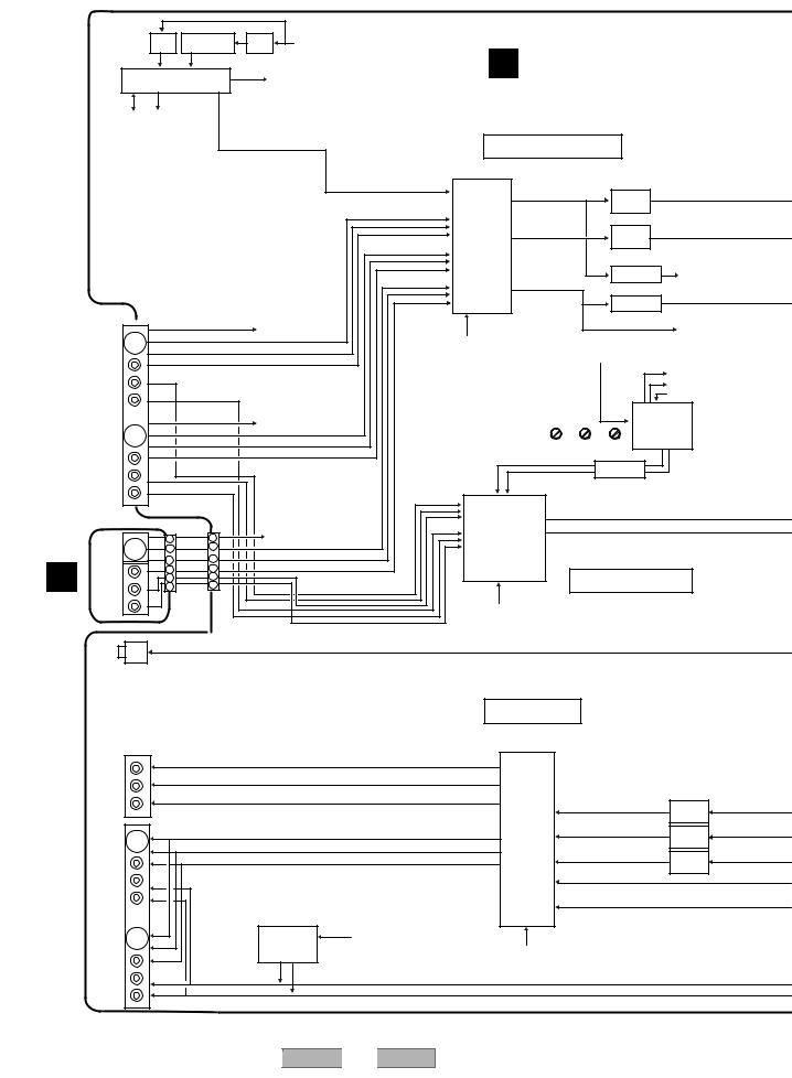
1 |
2 |
3 |
4 |
3.1.2 TUJB ASSY BLOCK DIAGRAM
A |
|
|
+32V |
+5V |
|
+6V |
|
|
|
|
|
|
|
|
|
|
|
|
|
|
TUON<u-com> |
|
|
|
|
|
|
|
|||||
|
|
|
Reg. |
Ripple Filter |
SW. |
B TUMJ ASSY (VWV1960) |
||||||||||
|
|
|
|
|
||||||||||||
|
|
U3001 |
|
|
|
|
|
|
|
|||||||
|
|
V/U Tuner FrontEnd |
|
|
Audio |
|
||||||||||
|
|
VXF1022- |
|
|
|
|
<IC3105> |
|
|
|
|
|
|
|
|
|
|
|
SCL |
AFT |
|
|
|
|
|
|
|
|
|
|
|
|
|
|
|
SDA |
AGC |
|
|
|
|
|
|
|
|
|
|
|
|
|
|
|
<u-com> |
|
|
|
|
|
|
|
Video Input Circuit |
|
|
|
|||
|
|
|
|
|
|
|
|
|
|
|
|
|
|
|||
|
|
|
|
|
|
|
|
|
|
|
|
|
Q3344 |
|
|
|
|
|
|
|
|
|
|
|
|
|
|
24 |
V/Y |
LPF |
|
V/Y |
|
|
|
|
|
|
|
|
|
|
|
IC3301 |
|
|
|
|
||
B |
|
|
|
|
|
|
|
|
|
|
|
|
|
|
|
|
|
|
|
|
|
|
|
|
|
LA73030 |
|
|
Q3342 |
|
|
|
|
|
|
|
|
|
|
|
|
|
|
Video |
26 |
C |
LPF |
|
C |
|
|
|
|
|
|
|
|
|
|
|
|
|
|
|
|||
|
|
|
|
|
|
|
|
|
|
Selector |
|
|
|
|
|
|
|
|
|
|
|
|
|
|
|
|
|
|
|
Q3362 |
|
|
|
|
|
|
|
|
|
|
|
|
|
|
|
|
Sync-Sepa |
SYNCAFT<u-com> |
||
|
|
|
|
|
|
|
|
|
|
|
28 |
SYNC |
Q3301 |
|
|
|
|
|
|
|
|
|
|
|
|
|
|
|
|
|
|
|
|
|
|
|
|
|
|
|
|
|
|
|
|
|
Comparator |
SYNCMAIN |
||
|
|
|
|
|
|
|
|
|
|
|
|
|
|
|
||
|
|
JA2832 |
S |
|
|
|
SDET1 <u-com> |
|
|
|
|
|
|
SYNC<u-com> |
||
|
|
C |
|
|
|
|
|
|
|
|
|
|||||
|
|
|
|
|
|
|
|
|
SELV1 YVSEL |
|
|
|
|
|
|
|
|
|
|
Y |
|
|
|
|
|
|
|
|
|
|
|
|
|
|
|
|
|
|
|
|
|
|
SELV2 SWSTBY |
|
Audio <U3001:U/V Tuner> |
|
||||
|
|
|
V |
|
|
|
|
|
|
SELV3 |
<u-com> |
|
|
|||
|
|
IN1 |
L |
|
|
|
|
|
|
|
|
|
|
|
STID |
|
|
|
(Rear) |
|
|
|
|
|
|
|
|
|
|
|
SUID |
<u-com> |
|
|
|
|
|
|
|
|
|
|
|
|
|
|
|
|
||
|
|
|
R |
|
|
|
|
|
|
|
|
|
|
|
MUTE |
|
C |
|
|
S |
|
|
|
|
|
|
|
|
|
|
IC3105 |
|
|
|
|
|
|
|
|
SDET3 <u-com> |
|
|
|
|
|
MPX Audio |
|
|||
|
|
|
C |
|
|
|
|
|
|
|
|
|
|
Decoder |
|
|
|
|
|
Y |
|
|
|
|
|
|
|
|
|
|
|
|
|
|
|
|
|
|
|
|
|
|
|
|
ATT Wideband Spectral |
CXA2064M |
|
|||
(VWV1964) |
|
|
V |
|
|
|
|
|
|
|
|
|
Q3101 |
|
|
|
|
|
|
|
|
|
|
|
|
|
|
|
|
|
|
||
|
IN3 |
|
|
|
|
|
|
|
|
|
|
15kHz LPF |
|
|
||
|
(Rear) |
L |
|
|
|
|
|
|
|
|
|
|
|
|||
|
|
|
|
|
|
|
|
|
|
|
|
|
|
|
||
|
|
R |
|
|
|
|
|
|
|
|
|
|
|
|
|
|
|
|
|
|
|
|
|
|
|
IC2801 |
|
5 |
L |
|
|
|
|
|
|
|
|
|
|
|
|
|
Audio Selector |
|
|
|
||||
|
|
|
|
|
|
|
|
|
26 |
R |
|
|
|
|||
|
|
S |
|
|
|
|
|
|
with |
|
|
|
|
|||
|
|
4 |
|
12 |
|
SDET2 <u-com> |
|
|
|
|
|
|
|
|||
|
JA1301 |
|
|
|
Electric A.T.T |
|
|
|
|
|
||||||
|
|
|
|
|
|
|
|
|
|
|||||||
|
C |
|
|
|
|
|
|
|
|
|
||||||
|
14 |
|
2 |
|
|
|
|
|
|
|
|
|||||
|
|
|
|
|
|
|
|
|
|
|
|
|
|
|
||
|
|
|
Y |
|
|
|
|
|
LC75342M |
|
|
|
|
|
||
|
|
|
12 |
|
4 |
|
|
|
|
|
|
|
|
|||
|
|
JA1302 |
V |
|
|
|
|
|
|
|
|
|
||||
|
|
10 |
|
6 |
|
|
|
|
|
|
Audio Input Circuit |
|
||||
|
|
|
L |
6 |
|
10 |
|
|
|
|
|
|
|
|||
|
|
IN2 |
8 |
|
8 |
|
|
|
|
|
|
|
||||
|
|
|
|
|
|
|
|
|
|
|
|
|
|
|
|
|
D |
|
(Front) |
R |
|
|
|
|
|
|
|
|
|
|
|
|
|
|
|
|
|
|
|
|
|
|
|
|
|
|
|
|
||
ASSYFRJB |
C |
|
|
CN1301 |
|
CN3002 |
|
|
|
EVOLCLK |
|
|
|
|
|
|
|
|
|
|
|
|
EVOLDATA <u-com> |
|
|
|
|
||||||
|
|
|
|
|
|
EVOLCE |
|
|
|
|
|
|||||
JA3081 |
|
|
|
|
|
|
|
|
|
|
|
|
||||
Optical |
|
|
|
|
|
|
|
|
|
|
|
|
||||
|
|
|
|
|
|
|
|
|
|
|
|
|
|
|
|
|
|
|
OUT |
|
|
|
|
|
|
|
|
|
|
|
|
|
|
|
|
|
|
|
|
|
|
|
|
Output Circuit |
|
|
|
|||
|
|
|
|
|
|
|
|
|
|
|
|
S1 |
|
|
|
|
|
|
JA3582 |
|
|
Y |
|
|
|
|
25 |
|
|
|
|
|
|
|
|
Component |
|
|
Cb |
|
|
|
|
23 |
|
|
|
|
|
|
E |
|
|
|
|
|
|
|
|
|
IC3501 |
|
|
|
|
|
|
|
OUT |
|
|
Cr |
|
|
|
|
21 |
|
|
|
|
|
||
|
|
|
|
|
|
|
|
|
LA73054 |
|
16 |
|
|
|
||
|
|
|
|
|
|
|
|
|
|
|
Video Driver |
|
LPF |
|
||
|
|
|
|
|
|
|
|
|
|
|
|
|
|
|||
|
|
|
|
|
|
|
|
|
|
|
with LPF |
|
|
|
|
|
|
|
JA3551 |
|
|
Y |
|
|
|
|
28 |
|
|
14 |
|
LPF |
|
|
|
|
|
|
|
|
|
|
|
|
|
|
||||
|
|
|
|
|
C |
|
|
|
|
31 |
|
|
11 |
|
|
|
|
|
|
|
|
V |
|
|
|
|
33 |
|
|
|
LPF |
|
|
|
|
|
|
|
|
|
|
|
|
|
|
|
|
|||
|
|
|
|
|
|
|
|
|
|
|
|
|
|
|
|
|
|
|
OUT1 |
|
|
|
|
|
|
|
|
|
|
6 |
|
|
|
|
|
|
|
|
|
|
|
|
|
|
|
|
|
|
|
|
|
|
|
|
|
|
|
|
|
|
|
|
|
8 |
|
|
|
|
|
|
Y |
|
|
|
|
|
LAMUTE |
|
|
|
|
|
|
|
|
|
|
|
|
|
|
|
|
|
|
|
|
|
|
|
|
|
|
|
C |
|
|
|
|
Muting |
RAMUTE |
|
525P |
|
|
|
|
|
|
|
|
Comp |
|
|
(Discrete) |
<MAIN> |
|
|
|
|
|
|
|||
|
|
|
|
|
|
|
|
|
|
|
|
|
||||
|
|
OUT2 |
|
|
|
|
|
|
|
|
|
|
|
|
|
|
F |
|
|
|
|
|
L |
|
|
|
|
|
|
|
|
|
|
|
|
|
|
|
R |
|
|
|
|
|
|
|
|
|
|
|
|
|
|
|
|
|
|
|
|
|
|
|
|
|
|
|
|
16 |
1 |
|
|
|
|
|
2 |
|
DVR-310-S |
3 |
|
|
|
4 |
|
|
|
|
|
|
|
|
|
|
|
|
|
|
|
||||
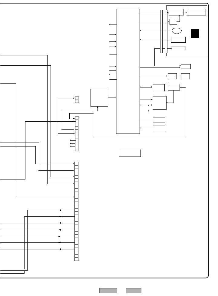
5 |
|
6 |
|
7 |
|
|
|
8 |
|
|
|
|
|
|
|
IC1001 |
|
V1001 |
A |
|
|
|
|
FLCLK, FLDATA, FLSTB |
FL Driver |
|
FL Display |
|
|
|
|
|
|
|
|
PT6315 |
|
|
|
|
|
|
|
|
|
|
|
|
|
|
|
|
|
|
|
Q1001 |
|
|
|
|
|
EVOLCLK |
|
FLPON |
|
+6V |
|
|
|
|
|
|
|
|
SW |
|
|
|
|
|
|
<IC2801> EVOLDATA |
|
|
|
S1003 |
|
|
|
|
|
EVOLCE |
IC2001 |
JOGA, JOGB |
|
|
|
||
|
|
|
JOG |
|
F |
|
|||
|
|
SDET1 |
|
|
|
|
|
||
|
|
|
|
|
|
|
|
||
|
|
<JA1301, SDET2 |
Tuner/FL |
|
|
S1001-S1008 |
|
||
|
|
JA2832> SDET3 |
KEY1, KEY2, KEY3 |
|
|||||
|
|
|
|
|
|||||
|
|
|
Control U-com |
Front Keys |
FLKY |
|
|||
|
|
<Q3362> SYNCAFT |
|
|
|
|
|||
|
|
PD5942A8 |
|
|
|
|
|
||
|
|
|
|
|
IC1002 |
|
|
||
|
|
<IC3301> SYNC |
|
|
|
|
ASSY |
|
|
|
|
|
|
|
IR Detector |
|
|||
|
|
SELV1 |
|
|
|
|
|||
|
|
|
|
CN2005 |
|
|
(VWG2432) |
|
|
|
|
<IC3301> SELV2 |
|
|
CN1001 |
|
|
||
|
|
SELV3 |
|
|
|
|
|
||
|
|
SWSTBY |
|
|
JA2201 |
B |
|||
|
|
|
|
|
|
|
|
||
|
|
<U3001> AGC |
|
SELIR |
|
|
SR In |
|
|
|
|
<IC3105> STID,SAPID |
|
|
|
Q2640 |
|
|
|
|
|
|
|
|
|
|
|
|
|
|
|
<IC3105> MUTE |
|
|
|
FAN |
FAN |
|
|
|
|
|
|
|
|
Driver |
|
||
|
|
<Q3006,etc> TUON |
|
|
|
|
|
|
|
|
|
|
|
|
|
|
|
|
|
|
|
|
|
|
IC2251 |
BT2272 |
|
|
|
|
|
|
|
SCLEEP |
|
BUP |
|
||
|
|
|
|
EEPROM |
Battery |
|
|||
|
|
|
|
SDAEEP |
|
|
|
||
|
|
|
|
|
|
|
|
||
|
|
ASCK |
|
|
|
|
|
|
|
|
|
|
|
BR24L32F-W |
|
|
|
||
|
|
SST to M |
|
|
|
|
|
||
|
|
|
|
|
|
|
|
|
|
PCMOUT |
2 |
SSM to TSYS |
|
XINTRA |
|
|
|
|
|
HST to M |
|
IC2271 |
|
|
|
|
|||
|
|
|
|
|
|
||||
|
|
HSM to TSYS |
|
SCL |
Real-Time |
|
|
|
|
CN2009 |
XRESET |
|
Clock |
|
|
|
|
||
|
SDA |
|
|
|
|
||||
< from DRIVE > |
|
|
RS5C372A |
|
|
|
|||
|
|
|
|
|
|
|
|
||
|
|
|
|
Other Devices |
|
|
|
C |
|
BUP 21 |
|
|
|
X2001 |
|
|
|
|
|
|
|
XIN, XOUT |
Ceramic |
|
|
|
|
||
SPDIF |
20 |
|
|
|
Resonator |
|
|
|
|
|
|
|
|
|
|
|
|||
|
|
|
|
XRESETIN |
IC2521 |
|
|
|
|
|
|
|
|
Reset IC |
|
|
|
|
|
PCMOUT |
|
|
|
|
PST3245 |
|
|
|
|
8 |
|
|
|
|
|
|
|
|
|
|
|
|
|
|
|
|
|
|
|
RAMUTE |
5 |
|
|
|
|
|
|
|
|
525P |
4 |
|
|
|
|
|
|
|
|
LAMUTE |
3 |
|
|
|
|
|
|
|
|
CN2008 |
|
U-com I/F |
|
|
|
|
|
|
|
< from/to MAIN > |
|
|
|
|
|
|
|
||
SELR |
30 |
|
|
|
|
|
|
|
D |
|
|
|
|
|
|
|
|
||
|
29 |
|
|
|
|
|
|
|
|
SELL |
|
|
|
|
|
|
|
|
|
28 |
|
|
|
|
|
|
|
|
|
|
|
|
|
|
|
|
|
|
|
SELC |
27 |
|
|
|
|
|
|
|
|
26 |
|
|
|
|
|
|
|
|
|
|
|
|
|
|
|
|
|
|
|
SELV/Y |
25 |
|
|
|
|
|
|
|
|
24 |
|
|
|
|
|
|
|
|
|
|
|
|
|
|
|
|
|
|
|
|
23 |
|
|
|
|
|
|
|
|
|
22 |
|
|
|
|
|
|
|
|
SYNCMAIN |
21 |
|
|
|
|
|
|
|
|
20 |
|
|
|
|
|
|
|
|
|
|
|
|
|
|
|
|
|
|
|
|
19 |
|
|
|
|
|
|
|
|
|
18 |
|
|
|
|
|
|
|
|
L |
17 |
|
|
|
|
|
|
|
|
16 |
|
|
|
|
|
|
|
|
|
|
|
|
|
|
|
|
|
|
|
R |
15 |
|
|
|
|
|
|
|
|
14 |
|
|
|
|
|
|
|
E |
|
|
|
|
|
|
|
|
|
||
|
13 |
|
|
|
|
|
|
|
|
Cr/R |
|
|
|
|
|
|
|
|
|
12 |
|
|
|
|
|
|
|
|
|
|
|
|
|
|
|
|
|
|
|
Cb/B |
11 |
|
|
|
|
|
|
|
|
10 |
|
|
|
|
|
|
|
|
|
|
|
|
|
|
|
|
|
|
|
Y/G |
9 |
|
|
|
|
|
|
|
|
8 |
|
|
|
|
|
|
|
|
|
|
|
|
|
|
|
|
|
|
|
C |
7 |
|
|
|
|
|
|
|
|
6 |
|
|
|
|
|
|
|
|
|
|
|
|
|
|
|
|
|
|
|
Y |
5 |
|
|
|
|
|
|
|
|
4 |
|
|
|
|
|
|
|
|
|
|
|
|
|
|
|
|
|
|
|
|
3 |
|
|
|
|
|
|
|
|
|
2 |
|
|
|
|
|
|
|
|
|
1 |
|
|
|
|
|
|
|
|
CN3001 |
|
|
|
|
|
|
|
|
|
< to/from MAIN > |
|
|
|
|
|
|
F |
||
|
|
|
|
|
|
|
|
|
|
5 |
|
6 |
DVR-310-S |
7 |
|
|
|
8 |
17 |
|
|
|
|
|
|
||||
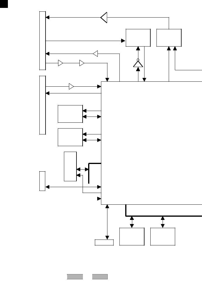
1 |
2 |
3 |
4 |
3.1.3 MAIN ASSY BLOCK DIAGRAM
A |
D MAIN ASSY |
|
|
|
|
|
|
|
|
|
|
|
|
|
|
|
|
|
(VWV1952) |
|
|
|
|
|
|
|
|
|
AUDIO LR OUT |
|
|
IC3251 |
|
||
|
CN2001 |
AUDIO LR IN |
|
|
|
IC3101 |
IC3201 |
|
|
|
|
|
AK5381VT |
PCM1742KE |
|||
|
|
|
|
|
||||
|
|
|
|
|
|
|
||
|
|
|
|
|
|
|
A/D |
DAC |
|
|
VIDEO Y,C,Yp,Cb,Cr OUT |
Q2101-Q2105 |
|
||||
B |
|
|
|
|
|
|||
|
|
|
|
|
|
|
|
|
|
|
VIDEO Y,C IN |
IC2301,IC2331,Q2203 |
IC3403 ADCCLKO |
|
|||
|
|
|
|
|
||||
|
|
|
|
|
|
|||
|
|
Q2402,Q2403 |
Q2222 |
|
|
|
|
|
|
|
|
|
|
|
|
||
|
|
TO TUNER u-COM |
|
|
|
|
|
|
|
|
|
IC3001 |
|
|
|
|
|
C |
CN3001 |
|
|
ECLK0 |
|
|
|
|
|
|
|
|
|
|
|
||
|
|
|
IC1301 |
|
|
IC1001 |
|
|
|
|
|
|
|
|
|
||
|
|
|
ENC |
|
|
|
M65672WG |
|
|
|
|
SDRAM |
|
|
|
|
|
|
|
|
|
|
|
|
|
|
|
|
MT48LC4M32B2TG-6 |
|
|
1 Chip System Codec |
|||
|
|
|
IC1201 |
DCLK0 |
|
|
|
|
|
|
|
|
|
|
|
|
|
|
|
|
DEC |
|
|
|
• MPEG2 PS Encode |
|
|
|
|
SDRAM |
|
|
|
• AC-3/Linear PCM Audio Encode |
|
|
|
W986416DH-6 |
|
|
|
• 2ch ATA/ATAPI Interface |
||
D |
|
TC75-K4S561632D |
|
|
|
|
• MPEG2 PS Decode |
|
|
IC1401 SDRAMATA |
|
|
|
• AC-3/MPEG1/Linear PCM Audio Decode |
|||
|
CN4401 |
BUSATA |
|
|
||||
|
To Writer |
|
|
|
|
|
|
|
|
|
|
ARCLK0 |
|
|
|
|
|
E |
|
|
|
|
|
|
|
|
|
|
|
|
|
SERIAL |
|
|
|
|
|
|
|
|
|
|
IC1102 |
IC1103 |
|
|
|
|
|
|
|
Backup |
|
|
|
|
|
|
|
|
FLASH |
|
|
|
|
|
CN1901 |
|
SRAM |
||
|
|
|
|
|
|
|||
|
|
|
|
|
|
|
VYW2116 |
CY62148VLL-70ZI |
F |
|
|
|
|
|
|
|
|
|
18 |
|
DVR-310-S |
|
|
|
|
|
|
1 |
2 |
|
|
|
3 |
|
4 |
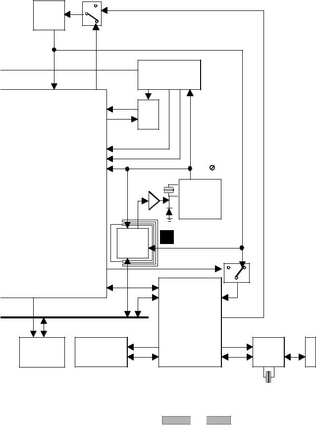
|
5 |
|
6 |
|
|
7 |
|
8 |
|
|
|
|
|
|
|
|
A |
VSS1195 |
|
|
|
|
|
|
|
|
X4102 |
|
|
|
|
|
|
|
|
VCXO |
|
|
|
|
|
|
|
|
Input Mster |
IC4101 |
|
|
|
|
|
|
|
clock |
|
|
|
|
|
|
|
|
|
|
|
|
|
|
|
|
|
ADMCLKI |
27M |
|
|
|
|
|
|
B |
|
|
|
|
|
|
|
||
|
|
|
|
|
|
|
|
|
|
|
33/36M |
|
IC3402 |
|
|
|
|
|
|
|
|
|
|
|
|
|
|
|
|
SM8707KV |
|
|
|
|
|
|
|
|
|
PLL IC |
|
|
|
|
|
|
SRC**I |
24 |
|
|
|
|
|
|
|
|
AD1895AYRS |
|
|
|
|
|
|
|
IC3301 |
SRC |
|
|
|
C |
|
|
|
SRC**O |
|
|
|
DVPLLCK(ADMCLKI) |
DVVPWM |
|
|
|
AMCLK1 |
36M |
|
|
|||
|
|
|
|
|
|
|||
|
|
AMCLK2 |
|
33M |
|
|
|
|
|
|
VMCLKI |
|
|
|
|
|
|
|
|
|
|
27M |
Master Clock |
|
|
|
|
|
|
|
|
Free Run |
|
|
|
|
|
IC4206 |
IC4205 |
|
|
|
||
|
|
|
|
|
|
|
|
|
|
|
|
|
TC7WHU04FU |
|
|
|
|
|
|
|
|
Play Mster clock |
|
|
D |
|
|
|
CN4702 |
|
|
|
|
|
|
|
|
|
|
|
|
|
|
|
|
|
CN2 |
|
MHLP ASSY |
|
|
|
|
|
|
IC1 |
|
|
|
|
||
|
|
|
E (VWV1991) |
|
|
|
||
|
|
PDY081A |
|
|
|
|
||
|
|
|
|
|
|
|
|
|
|
|
ALTERA |
|
|
|
|
|
|
|
|
|
|
DVVCLKO |
|
|
|
|
|
|
|
|
|
|
IC4009 |
|
|
|
|
|
|
|
|
|
|
E |
HCLK0 |
|
|
IC5202 |
VCLKI |
|
|
||
|
|
|
|
|
|
|
||
|
|
HOST BUS |
|
UPD72893AGD-LML |
|
|
|
|
|
|
|
|
UPD72852AGB-8EU |
|
|||
|
|
|
|
LINK/DV CODEC |
|
|||
|
|
MCLK |
SCLK |
|
|
|||
|
|
|
|
|
CN5102 |
|||
IC1101 |
|
IC5204 |
|
|
|
|
IC5101 |
|
|
|
|
|
|
|
|||
CPU SDRAM |
DV SDRAM |
|
|
|
|
Phy |
|
|
K4S281632E-TC75 |
K4S161622D |
|
|
|
|
|
DV |
|
|
|
|
|
|
|
|
|
F |
|
|
|
|
DVR-310-S |
7 |
|
19 |
|
|
5 |
|
6 |
|
|
|
8 |
|
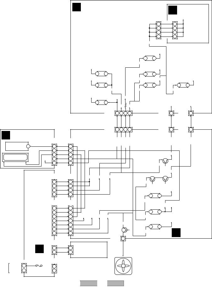
1 |
2 |
3 |
4 |
3.1.4 POWER BLOCK DIAGRAM
A |
|
|
|
|
|
|
|
|
|
|
|
|
|
|
|
|
|
|
|
|
|
|
|
|
|
|
|
|
|
|
D MAIN ASSY |
|
|
|
|
|
|
|
|
|
E MHLP ASSY |
||||||
|
|
|
|
|
|
|
|
|
|
|
|
|
|
|
|
|
|
|
|
||||
|
|
|
|
|
|
|
|
|
|
|
|
|
|
|
|
|
CN4702 |
CN2 |
|
V+3D |
|
||
|
|
|
|
|
|
|
|
|
|
|
|
|
|
|
|
|
(30P) |
(30P) |
|
|
|||
|
|
|
|
|
|
|
|
|
|
|
|
|
|
|
|
|
|
16 |
V+3D |
16 |
|
|
|
|
|
|
|
|
|
|
|
|
|
|
|
|
|
|
|
|
|
|
|
|
|
||
|
|
|
|
|
|
|
|
|
|
|
|
|
|
|
|
|
|
17 |
V+3D |
17 |
|
|
|
|
|
|
|
|
|
|
|
|
|
|
|
|
|
|
|
|
|
|
|
|
|
||
|
|
|
|
|
|
|
|
|
|
|
|
|
|
|
|
|
|
18 |
V+3D |
18 |
|
|
|
|
|
|
|
|
|
|
|
|
|
|
|
|
|
|
|
|
|
|
|
|
|
||
|
|
|
|
|
|
|
|
|
|
|
|
|
|
|
|
|
|
19 |
V+3D |
19 |
|
|
|
|
|
|
|
|
|
|
|
|
|
|
|
|
|
|
|
|
|
|
|
|
|
||
B |
|
|
|
|
|
|
|
|
|
|
|
|
|
|
|
V+3D |
|
|
|
|
|
|
|
|
|
|
|
|
|
|
|
|
|
|
|
|
|
|
|
|
|
|
|
|
|
|
|
|
|
|
|
|
|
|
|
|
|
|
|
|
|
|
|
IC4008 |
V+PRA |
|
|
|
|
||
|
|
|
|
|
|
|
|
|
|
|
|
|
|
|
|
1.2V REG. |
|
|
|
|
|
|
|
|
|
|
|
|
|
|
|
|
|
|
|
|
|
|
|
1 |
3 |
|
|
|
|
|
|
|
|
|
|
|
|
|
|
|
|
|
|
|
|
|
V+1R2V |
|
|
|
|
|
|
|
|
|
|
|
|
|
|
|
|
V+5A |
IC4004 |
|
|
|
|
|
IC4007 |
V+3V |
|
|
|
|
|||
|
|
|
|
|
|
|
|
|
5V REG. |
|
|
|
|
|
3.3V REG. |
|
|
|
|
|
|
||
|
|
|
|
|
|
|
|
|
5 |
1 |
|
|
|
|
|
5 |
4 |
|
|
|
|
|
|
|
|
|
|
|
|
|
|
V+5D |
IC4006 |
|
|
|
|
V+4V |
IC4002 |
V+3D |
|
IC5002 |
V+2R5 |
||||
|
|
|
|
|
|
|
|
|
5V REG. |
|
|
|
|
|
3.3V REG. |
|
|
|
2.5V REG. |
||||
|
|
|
|
|
|
|
|
|
5 |
1 |
|
|
|
|
|
1 |
3 |
|
|
|
7 |
1 |
|
|
|
|
|
|
|
|
|
|
|
V+6V |
|
|
|
V+4V |
|
|
|
|
V+3D |
|
|
|
|
C |
|
|
|
|
|
|
|
V+12A |
IC4001 |
V+13V |
V+1R2V |
|
|
|
|
|
|
|
|
||||
|
|
|
|
|
|
|
|
12V REG. |
|
|
|
|
|
|
|
|
|||||||
|
|
|
|
|
|
|
|
|
|
|
|
|
|
|
|
|
|
|
|
|
|||
|
|
|
|
|
|
|
|
|
5 |
8 |
|
|
|
|
|
|
|
|
V+5VO |
|
V+5RP |
||
|
|
|
|
|
|
|
|
|
|
|
|
|
V+6V |
V+4V |
|
|
|
|
|||||
|
|
|
|
|
|
|
|
|
|
|
|
|
|
|
|
|
|
|
|
|
|||
|
|
|
|
|
|
|
|
|
|
CN4001 |
2 |
4 |
6 |
8 |
|
|
CN2001 |
1 |
CN3001 |
1 |
|||
|
|
|
|
|
|
|
|
|
|
(8P) |
|
|
|
|
|
|
|
|
(32P) |
|
|
(21P) |
|
|
|
|
|
|
|
|
|
|
|
CN2003 |
V+13SW |
V+6SW |
V+2 4SW |
V+4SW |
|
|
CN3001 |
V+5VO |
CN2008 |
V+5VI |
|||
|
|
|
|
|
|
|
|
|
|
2 |
4 |
6 |
8 |
|
|
1 |
1 |
||||||
F FLKY ASSY |
|
|
|
|
|
|
|
(8P) |
|
|
|
|
|
|
|
|
(32P) |
|
|
(21P) |
|
||
CN1001 |
CN2005 |
|
|
|
|
V+13SW |
V+6SW |
V+2 4SW |
V+4SW |
|
|
|
|
V+5VO |
|
|
V+5VI |
||||||
|
|
|
(19P) |
|
(19P) |
|
|
|
|
|
|
|
|
|
|
|
|||||||
IC1001 |
VEE 30 |
|
1 |
|
V–28V |
19 |
|
|
|
|
|
|
|
|
|
|
|
||||||
FL Driver |
|
FLDC – |
|
|
|
|
|
|
|
|
|
|
|
||||||||||
|
|
|
2 |
18 |
|
|
|
|
|
|
|
|
|
|
|
|
|
|
|
|
|
||
D |
|
|
|
|
|
|
|
|
|
|
|
|
|
|
|
|
|
|
|
|
|
||
|
|
3 |
FLDC + |
17 |
|
|
|
|
|
|
|
|
|
|
|
|
V+5VO |
|
|
|
|||
V1001 |
|
|
|
|
|
|
|
|
|
|
|
|
|
|
|
|
Q2621 |
|
|
|
|
||
|
|
14 V+13SW (NC) |
|
|
|
|
|
|
|
|
|
|
|
|
|
|
|
|
|
||||
FL TUBE |
|
V+5E |
6 |
|
|
|
|
|
|
|
|
|
|
|
|
|
|
|
|
||||
|
|
|
18 |
|
V+5E |
2 |
|
|
|
|
|
|
|
|
|
|
|
|
|
|
|
|
|
|
|
|
|
|
|
|
|
|
|
|
|
|
|
|
V+6SW |
|
|
|
|
||||
|
|
|
|
|
|
|
|
|
|
|
|
|
|
|
|
|
|
|
|
|
|||
|
|
|
|
|
|
|
|
|
|
|
|
|
|
|
|
|
|
|
V+5VI |
|
|
|
|
|
|
|
CN202 |
|
CN2001 |
|
|
|
|
|
|
|
|
|
Q2531 |
|
Q2532 |
|
|
|
|
||
|
|
|
(8P) |
|
|
(8P) |
V+4SW V+2_4SW |
V+6SW |
|
|
|
|
|
|
|
|
|
|
|
|
|||
|
|
|
2 |
SW+4V |
2 |
|
|
|
|
|
|
|
|
|
V+6E |
|
|
|
|
|
|
|
|
|
|
|
|
|
|
|
|
|
|
|
|
|
|
|
|
|
|
|
|
|
|||
|
|
|
3 |
SW+4V |
3 |
|
|
|
|
|
|
|
|
|
|
|
|
|
|
|
|
|
|
|
|
|
|
|
|
|
|
|
|
|
|
|
|
|
|
|
|
|
|
|
|
||
|
|
UNIT |
5 |
SW+2.4V |
5 |
|
|
|
|
|
|
|
|
|
|
IC2541 |
V+3_3E |
|
|
|
|||
|
|
|
|
|
|
|
|
|
|
|
|
|
|
3.3V REG. |
|
|
|
|
|||||
|
|
7 |
SW+6V |
7 |
|
|
|
|
|
|
|
|
|
|
|
|
|
|
|||||
|
|
|
|
|
|
|
|
|
|
|
|
|
|
|
|
|
|
|
|||||
|
|
|
|
|
|
|
|
|
|
|
|
|
|
1 |
6 |
|
|
|
|
|
|||
|
|
|
|
|
|
|
|
|
|
|
|
|
|
|
|
|
|
|
|
|
|||
|
|
CN201 |
|
CN2004 |
|
|
|
|
|
|
|
|
V+6E |
|
|
|
|
|
|
|
|||
|
|
SUPPLY |
|
|
|
|
|
|
|
|
|
|
|
|
|
|
|
|
|
||||
E |
|
(13P) |
|
(13P) |
|
|
|
|
|
|
|
|
|
|
IC2551 |
V+5E V+5M |
|
|
|
||||
|
|
FLDC (–) |
|
|
|
|
|
|
|
|
|
|
|
|
|
|
|||||||
|
3 |
3 |
|
|
|
|
|
|
|
|
|
|
5V REG. |
|
|
|
|
|
|||||
|
|
|
|
|
|
|
|
|
|
|
|
|
|
|
|
|
|
||||||
|
|
5 |
FLDC (+) |
5 |
|
|
|
|
|
|
|
|
|
|
1 |
3 |
|
|
|
|
|
||
|
|
|
|
|
|
|
|
|
|
|
|
|
|
|
|
|
|
|
|||||
|
|
4 |
FL–28V |
4 |
V+37E |
V+18E |
V+6E V+13SW |
|
|
|
|
|
V+6E |
|
|
|
|
|
|
|
|||
|
|
|
|
|
|
|
|
|
|
|
|
|
|
|
|
||||||||
|
|
7 |
EV+37V |
7 |
|
|
|
|
|
|
|
|
|
|
IC2581 |
|
V+9 |
|
|
|
|||
|
|
|
|
|
|
|
|
|
|
|
|
|
|
|
|
|
|
||||||
|
|
|
EV+18V |
|
|
|
|
|
|
|
V+13SW |
|
9V REG. |
|
|
|
|
|
|||||
|
|
G POWER |
9 |
9 |
|
|
|
|
|
|
|
|
|
|
|
|
|||||||
|
|
|
|
|
|
|
|
|
|
|
|
|
|
1 |
3 |
|
|
|
|
|
|||
|
|
11 |
|
EV+6V |
11 |
|
|
|
|
|
|
|
|
|
|
|
B TUMJ ASSY |
||||||
|
|
|
|
|
|
|
|
|
|
|
|
|
|
|
|
||||||||
|
|
|
|
|
|
|
|
|
Q2640 |
|
V+13SW |
|
|
||||||||||
|
|
|
|
SW+13 |
|
|
|
|
|
|
|
|
|
||||||||||
|
|
13 |
|
13 |
|
|
|
|
|
|
|
|
|
|
|||||||||
|
|
|
|
|
|
|
|
|
|
|
|
|
|
|
|
|
|||||||
|
|
|
|
|
|
|
|
|
CN2006 |
1 |
|
|
|
|
|
||||||||
|
|
CN203 |
|
|
|
|
|
|
|
(2P) |
|
|
|
|
|
|
|
|
|
|
|
||
|
|
|
|
|
|
|
|
|
|
|
V+13FAN |
|
|
|
|
|
|
|
|
|
|||
|
|
(4P) |
|
|
|
DRIVE ASSY |
|
|
|
|
|
|
|
|
|
|
|
|
|||||
|
|
1 |
SW+12V |
|
|
|
|
|
|
|
|
|
|
|
|
|
|||||||
|
|
|
|
|
|
|
|
|
|
|
|
|
|
|
|
|
|||||||
|
|
4 |
SW+5V |
|
|
|
|
|
|
|
|
|
|
|
|
|
|||||||
|
|
|
|
|
|
R6 |
|
|
|
|
|
|
|
|
|
|
|
|
|
|
|
|
|
|
|
|
|
|
|
|
|
|
|
|
|
|
|
|
|
|
|
|
|
|
|
|
|
F |
CN1 |
F1 |
CN204 |
|
|
|
|
|
|
|
|
|
|
|
DC FAN |
|
|
|
|
|
|
|
|
(4P) |
|
|
|
|
|
|
|
|
|
|
|
MOTOR |
|
|
|
|
|
|
|
||||
LIVE |
1 |
4A/125V |
SW+12V |
|
|
|
|
|
|
|
|
|
|
|
|
|
|
|
|
||||
|
1 |
|
|
|
|
|
|
|
|
|
|
|
|
|
|
|
|
|
|
||||
|
|
|
|
|
|
|
|
|
|
|
|
|
|
|
|
|
|
|
|
|
|||
AC IN |
2 |
|
4 |
SW+5V |
|
|
|
|
|
|
|
|
|
|
|
|
|
|
|
|
|
|
|
NEUTRAL |
|
|
|
|
|
|
|
|
|
|
|
|
|
|
|
|
|
|
|
||||
|
|
|
|
|
|
|
|
|
|
|
|
|
|
|
|
|
|
|
|
|
|||
20 |
|
|
|
|
|
|
|
DVR-310-S |
|
|
|
|
|
|
|
|
|
|
|
|
|
||
1 |
|
|
|
|
|
|
2 |
|
|
|
|
|
|
|
3 |
|
|
|
|
|
|
4 |
|
5 |
6 |
7 |
8 |
A
B
C
D
E
F
|
|
|
|
|
|
|
|
|
DVR |
-310-S |
7 |
21 |
|
5 |
6 |
|
|
|
8 |
|
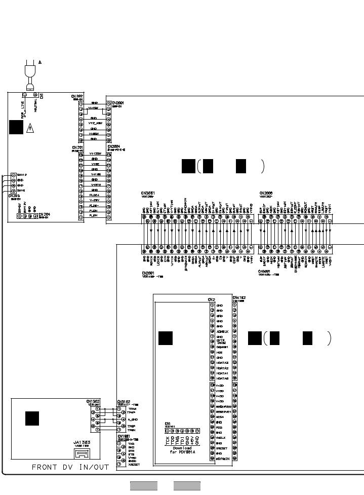
1 |
2 |
3 |
4 |
3.2 ATAB ASSY and OVERALL WIRING DIAGRAM
A
POWER CORD |
|
|
|
|
: ADG7021 |
|
|
|
|
B |
|
|
|
|
G |
|
|
|
|
POWER SUPPLY |
|
|
|
|
UNIT |
|
|
|
|
(VWR1373) |
B |
B 1/2 - B 2/2 |
|
|
WHT |
|
|||
C |
TUMJ ASSY (VWV1960) |
|
||
|
|
|
|
|
YEL |
|
|
|
|
D |
|
|
|
|
|
E |
|
D |
D 1/5 - D 5/5 |
|
MHLP ASSY |
MAIN ASSY |
||
E |
(VWV1991) |
|
(VWV1952) |
|
|
|
|
|
|
H |
|
|
|
|
DVJB ASSY |
|
|
|
|
(VWV1966) |
|
|
|
|
F |
|
|
|
|
22 |
DVR-310-S |
|
|
|
1 |
2 |
3 |
|
4 |
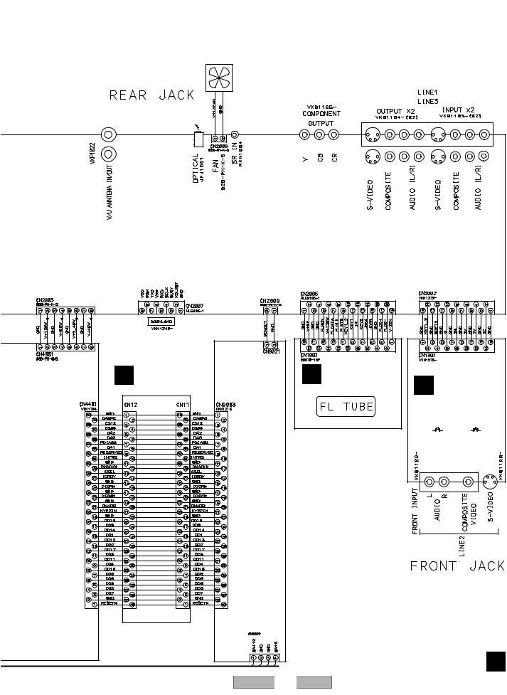
5 |
6 |
7 |
8 |
Note : When ordering service parts, be sure to refer to "EXPLODED VIEWS and PARTS LIST" or "PCB PARTS LIST". |
A |
DC FAN MOTOR : VXM1109
|
CN3582 |
JA3551 |
|
|
|
U3001 |
|
B |
JA3081 |
|
|
|
|
C |
A ATAB ASSY |
|
F FLKY ASSY |
C FRJB ASSY |
|
||
(VWV1968) |
|
(VWG2443) |
D |
|||
|
|
|
|
(VWV1964) |
|
|
CKS4052 |
VKN1805 |
|
|
|
|
|
|
|
|
|
DISC NAVI |
POWER |
|
|
R6 |
(VXX2898) |
|
|
|
|
|
DRIVEASSY |
|
|
|
E |
|
|
|
|
|
|
|
|
|
|
|
|
|
|
F |
|
|
|
|
|
A |
|
5 |
6 |
DVR-310-S |
7 |
|
8 |
23 |
|
|
|
||||
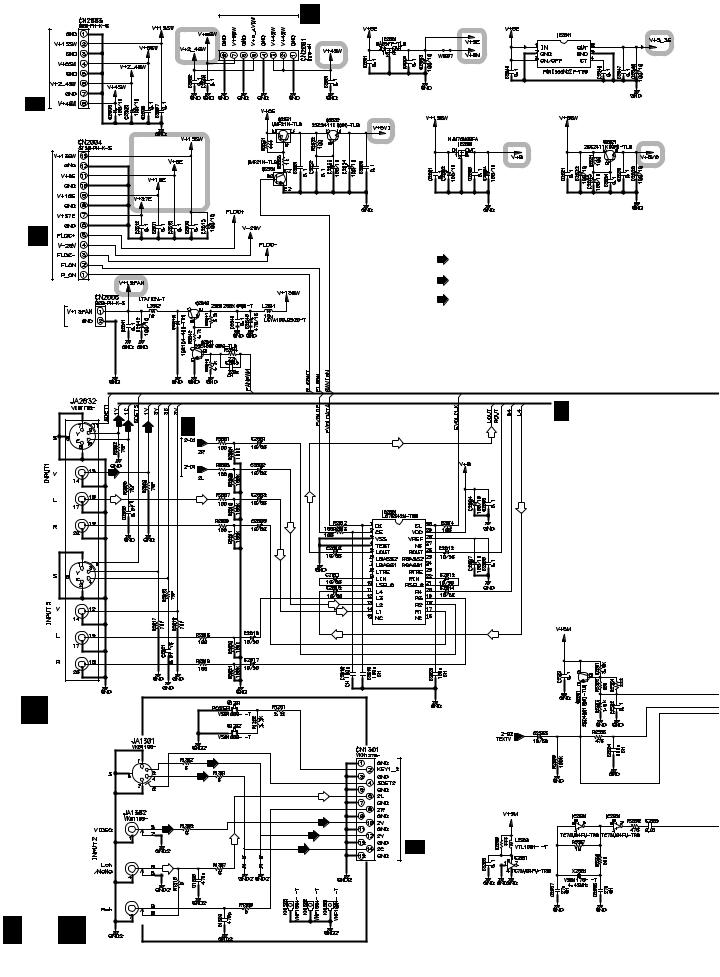
A
1 |
2 |
3 |
4 |
3.3 TUMJ(1/2), FRJB and DVJB ASSYS
G CN202
D 4/5 CN4001
B
C
D
G CN201
DC FAN
MOTOR
(Y) |
(C) |
: VIDEO SIGNAL ROUTE
(Y)
: S VIDEO SIGNAL ROUTE (Y)
(C)
: S VIDEO SIGNAL ROUTE (C)  : AUDIO SIGNAL ROUTE (L ch)
B 2/2
B 2/2
Audio Selector
E |
C FRJB ASSY |
|
|
|
|
|
(VWV1964) |
DISC NAVI |
|
|
|
|
|
(Y) |
|
|
|
|
Switches |
(C) |
|
|
|
|
S1201 : Standby On |
|
|
|
|
|
S1202 : Disc Navigator |
|
|
|
|
|
|
|
|
|
(Y) |
|
|
|
|
|
(C) |
|
|
D1301 |
D1303 |
D1304 |
D1301-D1304 UDZS5.6B-TRB |
F |
|
D1302 |
|||
|
|
|
|
|
B 1/2 C
|
|
|
|
|
24 |
|
DVR-310 |
-S |
|
1 |
2 |
|
|
|
B 2/2 CN3002
3 |
4 |
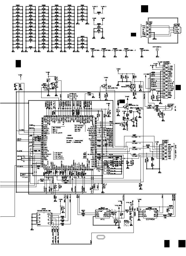
5 |
6 |
7 |
8 |
H |
A |
DVJB ASSY |
|
|
(VWV1966) |
D 5/5 CN5102 |
DV Terminal |
|
B |
B 1/2 TUMJ ASSY (VWV1960)
 6.8K 39K
*R2075 is mounted on W307.
1k 1/4
* R2075
TUFL U-com
* |
R2196 |
|
680 1/4 |
F CN1001
B 2/2
*L2023 |
VTL1081 |
|
|
*L2024 |
*L2023 to L2025 is mounted |
* L2025 |
|
|
on R2023 to R2025. |
|
10k |
10k |
|
R2197 |
* |
|
|
1/4 |
*R2196 is mounted on W129 |
||
680 |
|||
and R2197 is on W126. |
|||
: The power supply is shown with the marked box.
B 1/2 H
C
D
E
F
|
|
|
|
|
|
|
|
|
DVR |
-310-S |
7 |
25 |
|
5 |
6 |
|
|
|
8 |
|
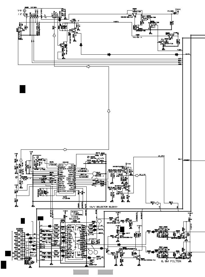
|
|
1 |
2 |
|
3 |
|
4 |
|
3.4 TUMJ ASSY(2/2) |
|
|
|
|
||
A |
|
|
|
|
|
|
|
|
|
|
(T) |
|
|
|
|
|
|
|
(T) |
|
|
|
|
|
|
VTL1081 |
VTL1081 |
(T) |
|
|
|
|
|
L3018 |
L3019 |
|
|
|
|
B |
|
|
|
|
(T) |
|
|
|
|
|
|
|
|
(T) |
|
|
|
|
|
|
|
|
|
|
|
|
|
(T) |
|
|
|
|
|
B 2/2 TUMJ ASSY (VWV1960) |
|
|
|
||
C |
|
|
|
|
|
|
|
|
|
|
|
|
(T) |
|
|
|
|
|
(T) |
|
|
|
|
D |
|
(T) |
Stereo |
|
|
|
|
|
|
|
|
|
|
||
|
|
Decoder |
|
|
|
|
|
|
|
|
|
|
|
|
|
|
|
|
CXA2064M |
|
|
|
|
|
|
|
|
|
21 |
|
|
|
|
|
(T) |
|
|
|
|
E |
|
|
|
|
|
|
|
|
|
|
1/2 |
|
|
|
|
|
|
B 1/2 |
B |
|
1 |
|
|
|
|
|
|
|
|
||
|
|
(C) |
|
|
(T) |
B1/2 |
(C) |
|
|
|
|
|
|||
|
|
|
|
|
|
|
|
|
CN1301 |
(Y) |
(C) |
|
|
|
|
|
(C) |
|
|
|
|
||
|
|
|
|
|
|
||
|
|
|
|
(C) |
|
|
|
|
|
STBY |
|
(V/Y) |
|
|
|
F |
|
|
3 |
4 |
|
|
|
C |
|
(Y) |
|
(V/Y) |
|||
|
|
(Y) |
|
||||
|
|
|
|
|
|
||
|
B 2/2 |
|
|
|
STBY |
|
|
|
|
|
|
|
|
|
|
|
26 |
|
|
DVR-310-S |
|
|
|
|
|
1 |
2 |
|
3 |
|
4 |
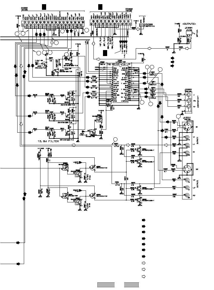
5
D 2/5 CN2001
9 |
7 |
(Y) |
(Cb) |
(Cr) |
|
(Y) |
(C) |
|
|
|
|
|
|
5 |
|
|
|
|
|
|
|
19 |
|
|
|
|
8 |
10 |
11 |
6 |
|
|
|
|
|
|
|
|
|
(Y) |
(Y) |
(C) |
|
|
|
|
|
(Cb) |
(C) |
|
|
|
|
|
|
(Cr) |
(Y) |
|
|
|
|
|
|
(Y)
(Cb)
(Cr)
(V/Y) (C)
(C)
(V/Y)
5
6 |
7 |
8 |
|
|
D 3/5 CN3001 |
|
|
A |
|
|
|
|
|
|
|
|
To DRIVE ASSY R6 CN9021 |
|||
18 |
220 |
470 |
|
|
|
|
(D) |
|
|
|
|
|
(D) |
|
|
|
|
|
|
|
(D) |
|
(D) |
|
(D) |
B 1/2 |
|
(Y) |
B |
|
|
|
|||
|
|
|
|
(Cb) |
|
|
|
|
12 16 |
(Cr) |
|
|
|
|
13 |
|
|
|
|
|
|
|
|
(C) |
|
(C) |
|
|
|
(Y) |
|
(Y) |
|
|
|
|
|
|
|
|
|
(Y) |
|
|
|
|
|
|
|
(Y) |
|
|
|
(Cb) |
|
(Cb) |
|
|
|
|
|
|
|
|
|
|
|
(Cr) |
|
|
|
(Cr) |
|
|
|
(C) (Y) |
|
|
|
14 |
15 |
|
|
|
|
|
|
||
|
|
|
|
|
|
|
|
|
|
|
C |
|
|
|
|
(Y) |
17 |
|
|
|
|
|
|
|
|
|
|
(C) |
|
20
DVR-310-S
6
: VIDEO SIGNAL ROUTE
(Y)
: COMPONENT VIDEO SIGNAL ROUTE (Y)
(Cb)
: COMPONENT VIDEO SIGNAL ROUTE (Cb)
(Cr)
: COMPONENT VIDEO SIGNAL ROUTE (Cr)
(Y)
: S VIDEO SIGNAL ROUTE (Y)
(C)
: S VIDEO SIGNAL ROUTE (C)
(T)
: VIDEO SIGNAL ROUTE (Tuner)
: AUDIO SIGNAL ROUTE (L ch)
(T)
: AUDIO SIGNAL ROUTE (Tuner)
(D) |
: AUDIO SIGNAL ROUTE (DIGITAL) |
B |
2/2 |
|
|||
|
|
|
|
|
|
|
|
27
7 |
8 |
D
E
F

1 |
2 |
|
|
3 |
|
4 |
3.5 MAIN ASSY(1/5) |
|
|
|
|
|
|
A |
D 4/5 |
D 5/5 |
|
|
|
|
D 2/5 |
D 5/5 |
|
|
|
|
|
|
D 4/5 |
|
|
|
|
|
|
|
|
|
|
|
|
B |
|
|
|
|
|
|
D 2/5 |
|
|
|
|
|
|
C |
|
|
|
|
|
|
D 2/5 |
|
|
|
|
|
|
D |
|
|
|
|
|
|
E |
|
|
|
|
|
|
|
|
|
|
|
|
(D) |
|
|
|
|
|
(D) |
D 3/5 |
(AT) |
|
|
|
|
|
|
F |
|
|
|
|
|
|
D 1/5 |
|
D 3/5 |
D 4/5 |
D 3/5 |
D 5/5 |
|
|
|
|
||||
|
|
|
|
|
||
|
|
|
|
|
|
|
|
|
|
|
|
|
28 |
|
DVR-310 |
-S |
|
|
|
1 |
2 |
|
|
|
3 |
4 |
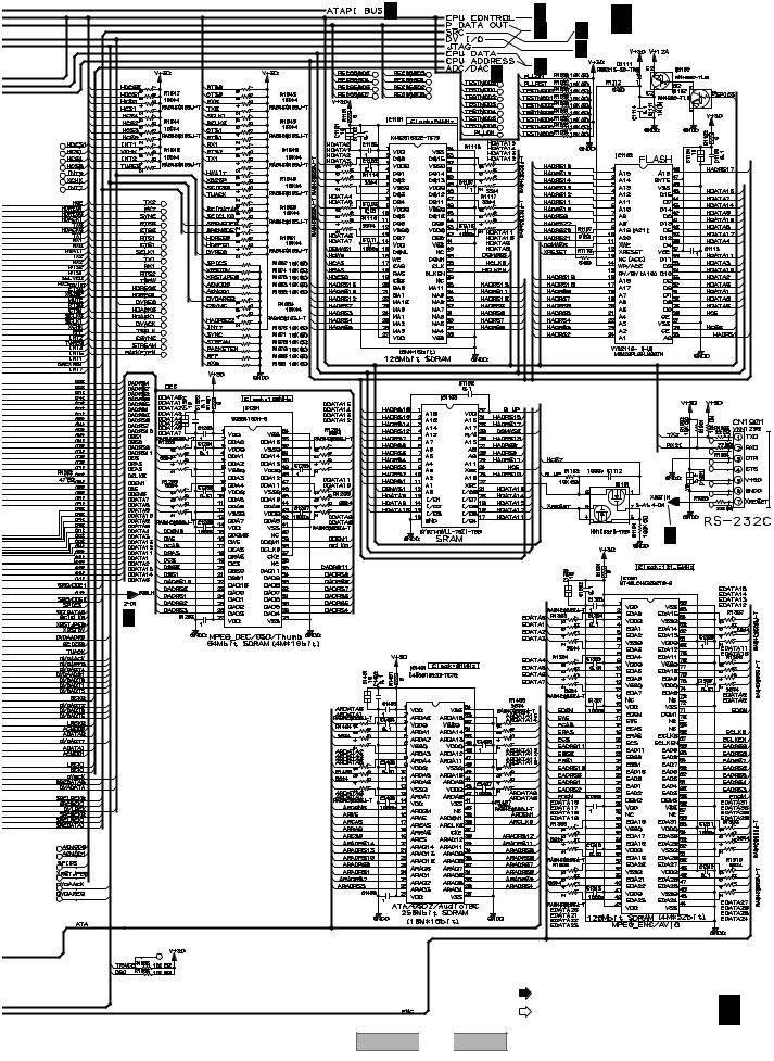
5 |
6 |
7 |
8 |
D 4/5 |
D 2/5-5/5 |
D 1/5 |
MAIN ASSY |
A |
|
D 4/5 D 3/5 |
(VWV1952)
|
D 5/5 |
D 3/5 |
D 4/5, 5/5 |
|
B
C
D 3/5, 4/5
D
D 2/5
E
F
(AT)
|
|
: ATA DATA SIGNAL ROUTE |
D 1/5 |
|
|
(D) |
|
|
|
: AUDIO SIGNAL ROUTE (DIGITAL) |
|
|
|
DVR-310-S |
29 |
5 |
6 |
7 |
8 |
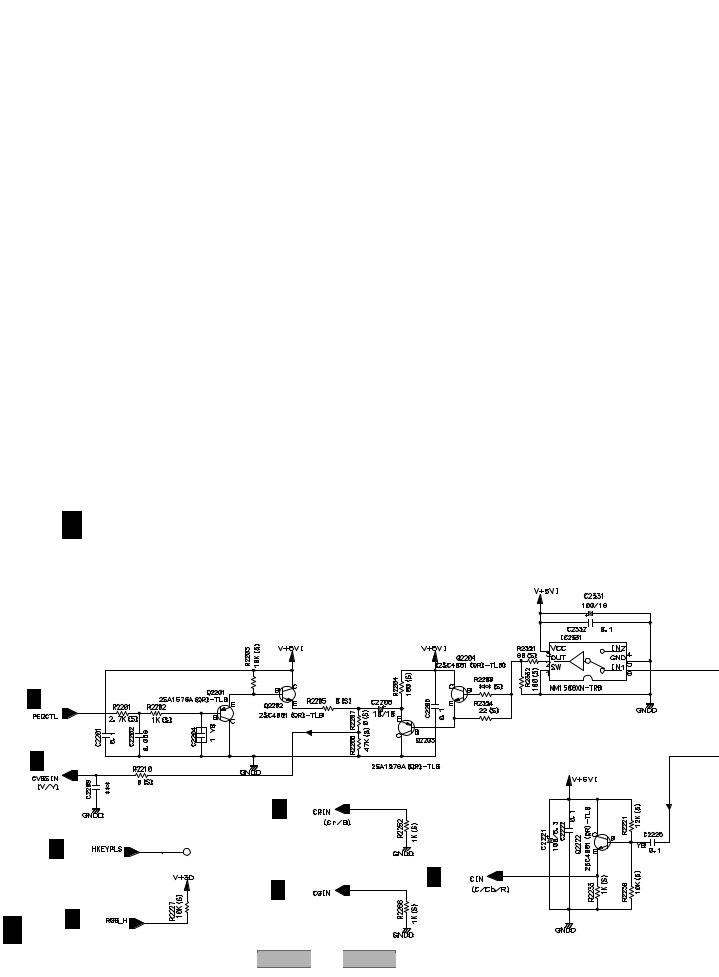
1 |
2 |
3 |
4 |
3.6 MAIN ASSY(2/5)
A
B
C
D 2/5 MAIN ASSY (VWV1952)
D
D 1/5
E |
|
|
|
D 1/5 |
|
|
|
|
|
D 1/5 |
|
D 1/5 |
|
|
|
F |
|
D 1/5 |
D 1/5 |
|
|
||
D 2/5 |
D 1/5 |
|
|
30 |
|
DVR-310-S |
|
1 |
2 |
3 |
4 |
Loading...