


DVR-540HX-S
DVD RECORDER
DVR-440HX-S
®
 ®
®
Discover the benefits of registering your product online at www.pioneer.co.uk
(www.pioneer-eur.com)
Operating Instructions

Thank you for buying this Pioneer product.
Please read through these operating instructions so you will know how to operate your model properly. After you have finished reading the instructions, put them away in a safe place for future reference.
IMPORTANT
CAUTION
RISK OF ELECTRIC SHOCK
DO NOT OPEN
The lightning flash with arrowhead symbol, within an equilateral triangle, is intended to alert the user to the presence of uninsulated "dangerous voltage" within the product's enclosure that may be of sufficient magnitude to constitute a risk of electric shock to persons.
CAUTION:
TO PREVENT THE RISK OF ELECTRIC SHOCK, DO NOT REMOVE COVER (OR BACK). NO USER-SERVICEABLE PARTS INSIDE. REFER SERVICING TO QUALIFIED SERVICE PERSONNEL.
The exclamation point within an equilateral triangle is intended to alert the user to the presence of important operating and maintenance (servicing) instructions in the literature accompanying the appliance.
D3-4-2-1-1_En-A
WARNING
This equipment is not waterproof. To prevent a fire or shock hazard, do not place any container filed with liquid near this equipment (such as a vase or flower pot) or expose it to dripping, splashing, rain or moisture.
WARNING
Before plugging in for the first time, read the following section carefully.
The voltage of the available power supply differs according to country or region. Be sure that the power supply voltage of the area where this unit will be used meets the required voltage (e.g., 230 V or 120 V) written on the rear panel.
CAUTION
This product is a class 1 laser product, but this product contains a laser diode higher than Class 1.
To ensure continued safety, do not remove any covers or attempt to gain access to the rear of the product.
Refer all servicing to qualified personnel.
The following caution labels appear on your unit. Location: top and rear of the unit
CAUTION |
CLASS 3B VISIBLE AND INVISIBLE LASER RADIATION WHEN OPEN, AVOID EXPOSURE TO THE BEAM. |
VRW2262 - A |
||||||
ATTENTION |
RADIATIONS LASER VISIBLES ET INVISIBLES DE CLASSE 3B QUAND OUVERT. ÉVITEZ TOUT EXPOSITION AU FAISCEAU. |
|
||||||
ADVARSEL |
KLASSE 3B SYNLIG OG USYNLIG LASERSTRÅLING VED ÅBNING. UNDGÅ UDSÆTTELSE FOR STRÅLING. |
|
||||||
VARNING |
KLASS 3B SYNLIG OCH OSYNLIG LASERSTRÅLNING NÄR DENNA DEL ÄR ÖPPNAD. UNDVIK ATT UTSÄTTA DIG FÖR STRÅLEN. |
|||||||
VORSICHT |
BEI GEÖFFNETER ABDECKUNG IST SICHTBARE UND UNSICHTBARE LASERSTRAHLUNG DER KLASSE 3B IM GERÄTEINNEREN VORHANDEN. |
|||||||
|
NICHT DEM LASERSTRAHL AUSSETZEN! |
|
||||||
PRECAUCIÓN CUANDO SE ABRE HAY RADIACIÓN LÁSER DE CLASE 3B VISIBLE E INVISIBLE. EVITE LA EXPOSICIÓN A LOS RAYOS LÁSER. |
||||||||
VARO! |
AVATTAESSA OLET ALTTIINA NÄKYVÄLLE JA NÄKYMÄTTÖMÄLLE LUOKAN 3B LASERSÄTEILYLLE. ÄLÄ KATSO SÄTEESEEN. |
|||||||
|
|
|
|
|
|
|
|
|
This product complies with the Low Voltage Directive (73/23/EEC, amended by 93/68/EEC), EMC Directives (89/336/EEC, amended by 92/31/EEC and 93/68/EEC).
WARNING
To prevent a fire hazard, do not place any naked flame sources (such as a lighted candle) on the equipment.
If you want to dispose this product, do not mix it with general household waste. There is a separate collection system for used electronic products in accordance with legislation that requires proper treatment, recovery and recycling.
Private households in the 25 member states of the EU, in Switzerland and Norway may return their used electronic products free of charge to designated collection facilities or to a retailer (if you purchase a similar new one).
For countries not mentioned above, please contact your local authorities for the correct method of disposal.
By doing so you will ensure that your disposed product undergoes the necessary treatment, recovery and recycling and thus prevent potential negative effects on the environment and human health.
Operating Environment
Operating environment temperature and humidity: +5 ºC to +35 ºC (+41 ºF to +95 ºF); less than 85 %RH (cooling vents not blocked)
Do not install this unit in a poorly ventilated area, or in locations exposed to high humidity or direct sunlight (or strong artificial light)
VENTILATION CAUTION
When installing this unit, make sure to leave space around the unit for ventilation to improve heat radiation (at least 10 cm at top, 10 cm at rear, and
10 cm at each side).
WARNING
Slots and openings in the cabinet are provided for ventilation to ensure reliable operation of the product, and to protect it from overheating. To prevent fire hazard, the openings should never be blocked or covered with items (such as newspapers, table-cloths, curtains) or by operating the equipment on thick carpet or a bed.
CAUTION
The STANDBY/ON switch on this unit will not completely shut off all power from the AC outlet. Since the power cord serves as the main disconnect device for the unit, you will need to unplug it from the AC outlet to shut down all power. Therefore, make sure the unit has been installed so that the power cord can be easily unplugged from the AC outlet in case of an accident. To avoid fire hazard, the power cord should also be unplugged from the AC outlet when left unused for a long period of time (for example, when on vacation).
This product is for general household purposes. Any failure due to use for other than household purposes (such as long-term use for business purposes in a restaurant or use in a car or ship) and which requires repair will be charged for even during the warranty period.
If the AC plug of this unit does not match the AC outlet you want to use, the plug must be removed and appropriate one fitted. Replacement and mounting of an AC plug on the power supply cord of this unit should be performed only by qualified service personnel. If connected to an AC outlet, the cut-off plug can cause severe electrical shock. Make sure it is properly disposed of after removal.
The equipment should be disconnected by removing the mains plug from the wall socket when left unused for a long period of time (for example, when on vacation).
POWER-CORD CAUTION
Handle the power cord by the plug. Do not pull out the plug by tugging the cord and never touch the power cord when your hands are wet as this could cause a short circuit or electric shock. Do not place the unit, a piece of furniture, etc., on the power cord, or pinch the cord. Never make a knot in the cord or tie it with other cords. The power cords should be routed such that they are not likely to be stepped on. A damaged power cord can cause a fire or give you an electrical shock. Check the power cord once in a while. When you find it damaged, ask your nearest PIONEER authorized service center or your dealer for a replacement.
Replacement and mounting of an AC plug on the power supply cord of this unit should be performed only by qualified service personnel.
IMPORTANT: THE MOULDED PLUG
This appliance is supplied with a moulded three pin mains plug for your safety and convenience. A 5 amp fuse is fitted in this plug. Should the fuse need to be replaced, please ensure that the replacement fuse has a rating of 5 amps and that it is approved by ASTA or BSI to BS1362.
Check for the ASTA mark |
or the BSI mark |
on the body of the fuse. |
If the plug contains a removable fuse cover, you must ensure that it is refitted when the fuse is replaced. If you lose the fuse cover the plug must not be used until a replacement cover is obtained. A replacement fuse cover can be obtained from your local dealer.
If the fitted moulded plug is unsuitable for your socket outlet, then the fuse shall be removed and the plug cut off and disposed of safely. There is a danger of severe electrical shock if the cut off plug is inserted into any 13 amp socket.
If a new plug is to be fitted, please observe the wiring code as shown below. If in any doubt, please consult a qualified electrician.
WARNING : THIS APPARATUS MUST BE EARTHED.
IMPORTANT: The wires in this mains lead are coloured in accordance with the following code: Green & Yellow : Earth Blue : Neutral Brown : Live
As the colours of the wires in the mains lead of this appliance may not correspond with the coloured markings identifying the terminals in your plug, proceed as follows ;
The wire which is coloured GREEN-AND-YELLOW must be connected to the terminal in the plug which is marked with the letter E or by the earth symbol  or coloured GREEN or GREEN-AND-YELLOW.
The wire which is coloured BLUE must be connected to the terminal which is marked with the letter N or coloured BLACK.
The wire which is coloured BROWN must be connected to the terminal which is marked with the letter L or coloured RED.
How to replace the fuse: Open the fuse compartment with a screwdriver and replace the fuse.
D3-4-2-1-2-1_B_En

Contents
01 Before you start
What’s in the box . . . . . . . . . . . . . . . . . . . 6
Putting the batteries in the
remote control. . . . . . . . . . . . . . . . . . . . . . 6
Using the remote control. . . . . . . . . . . . . . 6 Disc / content format playback compatibility . . . . . . . . . . . . . . . . . . . . . . . 7
About the internal hard disk drive . . . . . . 13 Symbols used in this manual . . . . . . . . . 14
02 Connecting up
Rear panel connections. . . . . . . . . . . . . . 15 Front panel connections . . . . . . . . . . . . . 16 Connecting a TV antenna . . . . . . . . . . . . 16
Easy connections . . . . . . . . . . . . . . . . . . 17
Using other types of audio/video output . 18 Connecting to a cable box or satellite receiver . . . . . . . . . . . . . . . . . . . . . . . . . . 19
Connecting an external decoder box (1) . 20 Connecting an external decoder box (2) . 21 Connecting to an AV amplifier/receiver . . 22 Connecting other AV sources . . . . . . . . . 23
Plugging in . . . . . . . . . . . . . . . . . . . . . . . 23
03 Controls and displays
Front panel . . . . . . . . . . . . . . . . . . . . . . . 24 Display . . . . . . . . . . . . . . . . . . . . . . . . . . 25 Remote control . . . . . . . . . . . . . . . . . . . . 26
04 Getting started
Switching on and setting up . . . . . . . . . . 29
Setting up the GUIDE Plus+® system . . . 32
4
05 Using the GUIDE Plus+® electronic program guide
The GUIDE Plus+® system. . . . . . . . . . . 37
Using the GUIDE Plus+® system . . . . . . 38
Areas . . . . . . . . . . . . . . . . . . . . . . . . . . . 40
GUIDE Plus+® FAQ and |
|
troubleshooting . . . . . . . . . . . . . . . . . . . |
50 |
06 Using the digital electronic program guide
The Digital EPG system . . . . . . . . . . . . . 53 Using the Digital EPG. . . . . . . . . . . . . . . 54 Setting timer programs . . . . . . . . . . . . . 55 Other useful EPG functions . . . . . . . . . . 56
07 Recording
About DVD recording . . . . . . . . . . . . . . . 57 About HDD recording. . . . . . . . . . . . . . . 58
Recorded audio . . . . . . . . . . . . . . . . . . . 59
Restrictions on video recording . . . . . . . 59 Using the built-in A.TV and
D.TV tuners. . . . . . . . . . . . . . . . . . . . . . . 60
Setting the picture quality/
recording time . . . . . . . . . . . . . . . . . . . . 63
Basic recording from the TV . . . . . . . . . . 64
Pause Live TV . . . . . . . . . . . . . . . . . . . . . 65
Setting a timer recording . . . . . . . . . . . . 66 Timer recording FAQ . . . . . . . . . . . . . . . 67 Simultaneous recording and playback (Chase Play) . . . . . . . . . . . . . . . . . . . . . . 68
Recording from an external
component . . . . . . . . . . . . . . . . . . . . . . . 68
Playing your recordings on other
DVD players . . . . . . . . . . . . . . . . . . . . . . 69
Initializing recordable DVD discs . . . . . . 71
En

08 Playback
Introduction . . . . . . . . . . . . . . . . . . . . . . 72 Basic playback . . . . . . . . . . . . . . . . . . . . 72
Using the Disc Navigator to browse
the contents of a disc . . . . . . . . . . . . . . . 77
Scanning discs . . . . . . . . . . . . . . . . . . . . 78
Playing in slow motion . . . . . . . . . . . . . . 79 Frame advance/frame reverse . . . . . . . . . 79
The Play Mode menu. . . . . . . . . . . . . . . . 79
Displaying and switching subtitles . . . . . 82 Switching DVD and DivX soundtracks . . . 83 Switching audio channels . . . . . . . . . . . . 83 Switching camera angles . . . . . . . . . . . . 84 Displaying disc information on-screen . . 84
13 The Disc Setup menu
Basic settings. . . . . . . . . . . . . . . . . . . . 114 Initialize settings. . . . . . . . . . . . . . . . . . 115 Finalize settings . . . . . . . . . . . . . . . . . . 115 Optimize HDD . . . . . . . . . . . . . . . . . . . 116 Initialize HDD . . . . . . . . . . . . . . . . . . . . 116
14 The Video Adjust menu
Setting the picture quality for TV and external inputs . . . . . . . . . . . . . . . . . . . 117
Setting the picture quality for disc
playback . . . . . . . . . . . . . . . . . . . . . . . . 119
09 Editing
Editing options . . . . . . . . . . . . . . . . . . . . 86
The Disc Navigator screen. . . . . . . . . . . . 87
15 The Initial Setup menu
Using the Initial Setup menu . . . . . . . . 121 Selecting other languages for language options . . . . . . . . . . . . . . . . . . . . . . . . . 135
Using Software Update (Digital tuner) . 136
10 Copying and backup
Introduction . . . . . . . . . . . . . . . . . . . . . . 99 One Touch Copy . . . . . . . . . . . . . . . . . . 100 Using Copy Lists . . . . . . . . . . . . . . . . . . 101 Using disc backup. . . . . . . . . . . . . . . . . 107
11 Using the Jukebox
Copying music to the HDD . . . . . . . . . . 109 Playing music from the Jukebox . . . . . . 110 Editing Jukebox albums . . . . . . . . . . . . 111
12 The PhotoViewer
Locating JPEG picture files . . . . . . . . . . 112
Playing a slideshow. . . . . . . . . . . . . . . . 112
16 Additional information
Minimum copying times. . . . . . . . . . . . 137 Manual recording modes . . . . . . . . . . . 138
Troubleshooting . . . . . . . . . . . . . . . . . . 139
On-screen displays and recorder
displays . . . . . . . . . . . . . . . . . . . . . . . . 143 Language code list . . . . . . . . . . . . . . . . 146
Country/Area code list . . . . . . . . . . . . . 146 Screen sizes and disc formats . . . . . . . 147
Handling discs . . . . . . . . . . . . . . . . . . . 148
Cleaning the pickup lens . . . . . . . . . . . 148 Hints on installation . . . . . . . . . . . . . . . 149
Moving the recorder . . . . . . . . . . . . . . . 149
Resetting the recorder . . . . . . . . . . . . . 149
Specifications. . . . . . . . . . . . . . . . . . . . 150
5
En

01 Before you start
Chapter 1
Before you start
What’s in the box
Please confirm that the following accessories are in the box when you open it.
•Remote control
•AA/R6P dry cell batteries x 2
•Audio/video cable (red/white/yellow)
•G-LINK™ cable
•RF antenna cable x 2 (1.5 m and 30 cm)
•Power cable
•These operating instructions
•Warranty card
•Don’t use different kinds of batteries together—although they may look similar, different batteries may have different voltages.
•Make sure that the plus and minus ends of each battery match the indications in the battery compartment.
•Remove batteries from equipment that isn’t going to be used for a month or more.
•When disposing of used batteries, please comply with governmental regulations or environmental public instruction’s rules that apply in your country or area.
Putting the batteries in the remote control
1 Insert two AA/R6P batteries into the battery compartment following the indications ( , ) inside the compartment.
 Important
Incorrect use of batteries can result in hazards such as leakage and bursting. Please observe the following:
•Don’t mix new and old batteries together.
WARNING
Do not use or store batteries in direct sunlight or other excessively hot place, such as inside a car or near a heater. This can cause batteries to leak, overheat, explode or catch fire. It can also reduce the life or performance of batteries.
Using the remote control
Please keep in mind the following when using the remote control:
•Make sure that there are no obstacles between the remote and the remote sensor on the unit.
•Remote operation may become unreliable if strong sunlight or fluorescent light is shining on the unit’s remote sensor.
•Remote controllers for different devices can interfere with each other. Avoid using remotes for other equipment located close to this unit.
6
En

Before you start |
01 |
•Replace the batteries when you notice a fall off in the operating range of the remote.
•When the batteries run down or you change the batteries, the remote control mode is reset to Recorder 1. See Remote Control Mode on page 132.
•Use within the operating range in front of the remote control sensor on the front panel, as shown.

 7 m
7 m
•You can control this recorder using the remote sensor of another Pioneer component using the CONTROL IN jack on the rear panel. See Rear panel connections on page 15 for more information.
Note that older models of DVD recorders and DVD writers may reject DVD-RW ver. 1.2 discs and/or corrupt the data on the disc. If you want to share DVD-RW discs between this recorder and an older recorder/writer, we recommend using ver. 1.1 discs.
The following table shows older Pioneer DVD recorders’ limited compatibility with DVDRW ver. 1.2 discs.
Model |
Playable |
Recordable |
DVR-7000 |
Yes1,2,3 |
No |
DVR-3100 / |
Yes1 |
No |
DVR-5100H |
|
|
|
|
|
1Discs should be finalized in this recorder before playing. Unfinalized VR mode and Video mode discs may not play.
2Cannot read the CPRM information will show in the display when you load a disc. However, this will not affect playback.
3Copy-once protected disc titles will not play.
Disc / content format playback compatibility
Compatible media
•DVD-RW ver. 1.1 / 1x / 1x to 2x, ver. 1.2 / 2x to 4x / 2x to 6x
•DVD-R ver. 2.0 /1x / 1x to 4x /
1x to 8x / 1x to 16x, ver. 2.1 / 1x to 8x / 1x to 16x
•DVD+RW 1x to 2.4x / 1x to 4x / 3.3x to 8x
•DVD+R 1x to 2.4x / 1x to 4x / 1x to 8x / 1x to 16x
•DVD-RAM ver. 2.0 / 2x, ver. 2.1 / 2x / 2x to 3x / 2x to 5x, ver. 2.2 / 2x / 2x to 3x / 2x to 5x
•DVD-R DL ver. 3.0 / 2x to 4x
•DVD+R DL 2.4x / 2.4x to 8x
DVD/HDD Recording and playback compatibility
This recorder can play and record all the currently popular DVD disc types, as well as providing HDD functionality. The table below shows some specific compatibility differences between the different disc types.
7
En

01 Before you start
|
|
HDD |
|
DVD-R |
|
DVD-RW |
DVD+R |
|
DVD |
DVD- |
|||||||||
|
|
|
|
|
+RW |
RAM |
|||||||||||||
|
|
|
|
|
|
|
|
|
|
|
|
|
|
|
|
||||
|
|
|
|
|
|
|
|
|
|
|
|
|
|
|
|
|
|
|
|
Marks used in this |
|
HDD |
DVD (VR) |
DVD (Video) |
|
DVD (VR) |
DVD (Video) |
DVD+R |
|
DVD+RW |
DVD-RAM |
||||||||
manual |
|
|
|
||||||||||||||||
|
|
|
|
|
|
|
|
|
|
|
|
|
|
|
|
|
|
|
|
|
|
|
*1 |
|
|
*1 |
*2 |
|
|
|
|
|
|
*13, 16 |
|
||||
|
|
|
|
|
|
|
|
|
|
|
|
|
|
|
|
|
|
|
|
Logos |
|
|
|
|
|
|
|
|
|
|
|
|
|
|
|
|
|
|
|
|
|
|
|
|
|
|
|
|
|
|
|
|
|
|
|
|
|
|
|
|
|
|
|
|
|
|
|
|
|
|
|
|
|
|
|
|
|
|
|
|
|
|
|
|
|
|
|
|
|
|
|
|
|
|
|
|
|
|
|
|
|
|
|
|
|
|
|
|
|
|
|
|
|
|
|
|
|
|
|
|
|
|
|
|
|
|
|
|
|
|
|
|
|
|
|
|
|
|
|
|
|
|
|
|
|
|
|
|
|
|
|
|
|
|
|
|
|
|
|
|
|
|
|
|
|
|
|
|
|
|
|
|
|
|
|
|
|
|
|
|
|
|
|
|
|
|
|
|
|
|
|
|
|
|
|
|
|
|
|
|
|
|
|
|
|
|
|
|
|
|
|
|
|
|
|
|
|
|
|
Re-recordable / |
|
|
*3 |
|
*3 |
|
|
|
|
|
|
|
*3 |
*14 |
|
|
|||
Erasable |
|
|
|
|
|
|
|
|
|
|
|
|
|
|
|
|
|
|
|
|
|
|
|
|
|
|
|
|
|
|
|
|
|
|
|
|
|
|
|
Editing of recorded |
|
|
|
|
*4 |
|
|
*4 |
|
*4 |
*4 |
|
|
|
|||||
programs |
|
|
|
|
|
|
|
|
|
|
|
|
|
|
|
|
|
|
|
|
|
|
|
|
|
|
|
|
|
|
|
|
|
|
|
|
|
|
|
Recording of Copy- |
|
|
*12 |
|
|
*12 |
|
|
|
|
|
|
|
|
|
*12 |
|
||
once protected |
|
|
|
|
|
|
|
|
|
|
|
|
|
|
|
|
|
|
|
material |
|
|
|
|
|
|
|
|
|
|
|
|
|
|
|
|
|
|
|
|
|
|
|
|
|
|
|
|
|
|
|
|
|
|
|
|
|
|
|
Playback in other |
|
n/a |
*5 |
|
*6 |
*7 |
*6 |
|
*6, 15 |
*8 |
|
*9 |
|
||||||
players/recorders |
|
|
|
|
|
|
|
|
|
|
|
|
|
|
|
|
|
|
|
|
|
|
|
|
|
|
|
|
|
|
|
|
|
|
|
|
|
|
|
Chase play |
|
|
|
|
|
|
|
|
|
|
|
|
|
|
|
|
|
|
|
|
|
|
|
|
|
|
|
|
|
|
|
|
|
|
|
|
|
|
|
16:9 and 4:3 pro- |
|
|
|
|
|
|
|
|
|
|
|
|
|
|
|
|
|
|
|
gram recording |
|
|
|
|
|
|
|
|
|
|
|
|
|
|
|
|
|
|
|
|
|
|
|
|
|
|
|
|
|
|
|
|
|
|
|
|
|
|
|
Bilingual broadcast |
*10, 11 |
*11 |
|
|
*11 |
|
|
|
|
|
|
|
|
|
*11 |
|
|||
recording of both |
|
|
|
|
|
|
|
|
|
|
|
|
|
|
|
|
|
||
audio channels |
|
|
|
|
|
|
|
|
|
|
|
|
|
|
|
|
|
|
|
|
|
|
|
|
|
|
|
|
|
|
|
|
|
|
|
|
|
|
|
Notes to table
*1 Must be initialized for VR mode recording (page 115) *2 Must be initialized for Video mode recording
(page 115)
*3 Erasable, but free space does not increase
*4 Cannot erase sections, edit chapters or use playlist editing
*5 Must be compatible with DVD-R(VR) playback
*6 Finalize using this recorder (may not playback in some units) (page 69)
*7 Must be compatible with DVD-RW(VR) playback
*8 Must be compatible with DVD+RW playback
*9 Must be compatible with DVD-RAM playback
*10 Only when HDD Recording Format is set to Video Mode Off (page 131)
*11 Only when the recording mode is not set to LPCM
*12 CPRM-compatible discs only
*13 Take the disc out of the cartridge before use. Only Panasonic and Maxell discs have been tested to work reliably with this recorder. Discs from other makers may become unusable when recorded or edited.
*14 Erasing a title does not increase the available recording time, nor increase the number of recordable titles left.
*15 Must be compatible with DVD+R playback
*16 Depending on the disc, it may have to be initialized before it can be recorded (page 115). In this case, initialization will take about 1 hour.
 is a trademark of DVD Format/Logo Licensing Corporation.
8
En
Before you start |
01 |
Using DVD-R DL/DVD+R DL discs
DVD-R DL (dual-layer) and DVD+R DL (double-layer) discs contain two recordable layers on a single side, giving about 1.8 times the recording capacity of a conventional single-layer disc. This unit can record to both DVD-R DL and DVD+R DL discs.
•If you intend to play DVD-R DL (Video mode) or DVD+R DL discs recorded on this unit on other DVD recorders/players, you must finalize them. (Note that some DVD recorders/players may not play even finalized DL discs.)
•Please read the information provided on the disc packaging carefully before purchasing DVD-R DL/DVD+R DL discs:
•Confirm the disc version: Use ver. 3.0 / 2x to 4x DVD-R discs.
•Confirm the recording speed: DVD-R should be compatible with 2x or 4x recording; DVD+R with 2.4x to 8x recording.
•This logo indicates that the disc is a DVD-R DL or DVD+R DL disc:
•Correct operation has been confirmed for DVD-R DL discs (ver. 3.0 / 2x, 4x) produced by the following manufacturers: Mitsubishi Kagaku Media, Verbatim (as of March 2005).
About DualDisc playback
A DualDisc is a new two -sided disc, one side of which contains DVD content –video, audio, etc. –while the other side contains non-DVD content such as digital audio material.
The non-DVD, audio side of the disc is not compliant with the CD Audio specification and therefore may not play.
It is possible that when loading or ejecting a DualDisc, the opposite side to that being played will be scratched. Scratched discs may not be playable.
The DVD side of a DualDisc plays in this product. DVD-Audio content will not play.
For more detailed information on the DualDisc specification, please refer to the disc manufacturer or disc retailer.
Other disc compatibility
In addition to DVD, this recorder is compatible with a wide range of disc types (media) and formats. Playable discs will generally feature one of the following logos on the disc and/or disc packaging. Note however that some disc types, such as recordable CD (and DVD), may be in an unplayable format—see below for further compatibility information.
Audio CD |
CD-R |
CD-RW |
Video CD |
Super Video CD (Super VCD) |
|
9
En

01 Before you start
CD-R/-RW compatibility
This recorder cannot record CD-R or CD-RW discs.
•Readable formats: CD-Audio, Video CD/ Super VCD, ISO 9660 CD-ROM* containing MP3, WMA, JPEG or DivX files.
*ISO 9660 Level 1 or 2 compliant. CD physical format: Mode1, Mode2 XA Form1. Romeo and Joliet file systems are both compatible with this recorder.
•Multi-session playback: Yes (except CDAudio and Video CD/Super VCD)
•Unfinalized disc playback: CD-Audio only
Compressed audio compatibility
•Compatible media: CD-ROM, CD-R, CD-RW
•Compatible formats: MPEG-1 Audio Layer 3 (MP3), Windows Media Audio (WMA)
•Sampling rates: 32 kHz, 44.1 kHz or 48 kHz
•Bit-rates: Any (128 Kbps or higher recommended)
•File extensions: .mp3, .wma (these must be used for the recorder to recognize MP3 and WMA files – do not use for other file types)
•File structure: Up to 99 folders / 999 files (if these limits are exceeded, only files and folders up to these limits are playable)
WMA (Windows Media Audio) compatibility
The Windows Media® logo printed on the box indicates that this recorder can playback Windows Media Audio content.
WMA is an acronym for Windows Media Audio and refers to an audio compression technology developed by Microsoft Corporation. WMA content can be encoded
by using Windows Media® Player for Windows® XP, Windows Media® Player 9 or
•Variable bit-rate (VBR) MP3 playback: Yes
•VBR WMA playback: No
•WMA encoder compatibility: Windows Media Codec 8 (files encoded using Windows Media Codec 9 may be playable but some parts of the specification are not supported; specifically, Pro, Lossless, Voice and VBR)
•DRM (Digital Rights Management)1 file playback: No
Windows Media® Player 10 series.
Microsoft, Windows Media, and the Windows logo are trademarks, or registered trademarks of Microsoft Corporation in the United States and/or other countries.
 Note
Note
1DRM (digital rights management) copy protection is a technology designed to prevent unauthorized copying by restricting playback, etc. of compressed audio files on devices other than the PC (or other recording equipment) used to record it. For detailed information, please see the instruction manuals or help files that came with your PC and/or software.
10
En
Before you start |
01 |
DivX video compatibility
DivX is a compressed digital video format
created by the DivX® video codec from DivX, Inc. This recorder can play DivX video files burned on CD-R/-RW/-ROM discs. Keeping the same terminology as DVD-Video, individual DivX video files are called "Titles." When naming files/titles on a CD-R/-RW disc prior to burning, keep in mind that by default they will be played in alphabetical order.
•Official DivX® Certified product.
•Plays all versions of DivX® video (including DivX® 6) with standard playback of DivX® media files.
•File extensions: .avi and .divx (these must be used for the recorder to recognize DivX video files). Note that all files with the .avi extension are recognized as MPEG4, but not all of these are necessarily DivX video files and therefore may not be playable on this recorder.
•File structure: Up to 99 folders or 999 files.
DivX, DivX Certified, and associated logos are trademarks of DivX, Inc. and are used under license.
DivX® VOD content
DivX
In order to play DivX VOD (video on demand) content on this recorder, you first need to register the recorder with your DivX VOD content provider. You do this by generating a DivX VOD registration code, which you submit to your provider.
Some DivX VOD content may only be playable a fixed number of times. When you load a disc containing this type of DivX VOD content, the remaining number of plays is shown on-screen and you then have the option of playing the disc (thereby using up one of the remaining plays), or stopping. If you load a disc that contains expired DivX VOD content (for example, content that has zero remaining plays), the message Rental Expired is displayed.
If your DivX VOD content allows an unlimited number of plays, then you may load the disc into your recorder and play the content as often as you like, and no message will be displayed.
 Important
•DivX VOD content is protected by a DRM (Digital Rights Management) system. This restricts playback of content to specific, registered devices.
•If you load a disc that contains DivX VOD content not authorized for this recorder, the message Authorization Error is displayed and the content will not play.
•Resetting the recorder (as described in
Resetting the recorder on page 149) will not cause you to lose your registration code.
11
En

01 Before you start
JPEG file compatibility
•Compatible formats: Baseline JPEG and EXIF 2.2* still image files
*File format used by digital still cameras
•Sampling ratio: 4:4:4, 4:2:2, 4:2:0
•Horizontal resolution: 160 to 5120 pixels
•Vertical resolution: 120 to 3840 pixels
•Progressive JPEG compatible: No
•File extensions: .jpg, .jpeg, .jpe, .jif, .jfif (must be used for the recorder to recognize JPEG files – do not use for other file types)
•File structure: The recorder can load up to 99 folders / 999 files at one time (if there are more files/folders that this on the disc then more can be reloaded)
PC-created disc compatibility
Discs recorded using a personal computer may not be playable in this unit due to the setting of the application software used to create the disc. In these particular instances, check with the software publisher for more detailed information.
Discs recorded in packet write mode (UDF format) are not compatible with this recorder.
Check the DVD-R/-RW or CD-R/-RW software disc boxes for additional compatibility information.
Dolby Digital
Manufactured under license from Dolby Laboratories. "Dolby" and the double-D symbol are trademarks of Dolby Laboratories.
12
DTS
“DTS” and “DTS Digital Out” are registered trademarks of Digital Theater Systems, Inc.
DVB
The Digital Video Broadcasting Project, or DVB for short, is a set of open standards for digital broadcasting, covering terrestrial, cable and satellite broadcasts.
Based around the MPEG-2 coding system, these open standards ensure that compliant systems are able to work together, independent of manufacturer.
DVB is extremely flexible, being able to deliver virtually any kind of digital content to the home, including High Definition and Standard Definition TV, broadband multimedia content and interactive services.
DVB is a registered trademark of the DVB Project.
En

Before you start |
01 |
About the internal hard disk drive
The internal hard disk drive (HDD) is a fragile piece of equipment. Depending on the conditions under which it is used, or through careless use, it is possible that the recorded contents will be damaged or lost completely, or that normal playback and recording will not be possible. Please understand that in the event of repair or replacement of the HDD or related components, all your HDD recordings will be lost.
Please use the recorder following the guidelines below to protect against possible HDD failure.
The HDD should not be regarded as a place to store recordings permanently. We recommend that you back up your important recordings onto DVD discs in order to protect against accidental loss.
Pioneer cannot under any circumstances accept responsibility for any direct or indirect loss arising from any inconvenience or loss of recorded material resulting from HDD failure.
•Do not move the recorder while it is on (this includes during EPG download when the display shows EPG).
•Install and use the recorder on a stable, level surface.
•Do not block the rear vent/cooling fan.
•Do not use the recorder in excessively hot or humid places, or in places that may be subject to sudden changes in temperature. Sudden changes in temperature can cause condensation to form inside the recorder. This can be a cause of HDD failure.
•While the recorder is switched on (including during EPG download when the display shows EPG), do not unplug from the wall socket or switch the electricity off from the breaker switch.
•Do not move the recorder immediately after switching it off. If you need to move the recorder, please follow the steps below:
1 After the message POWER OFF is shown in the display, wait at least two minutes.
2 Unplug from the wall socket.
3 Move the recorder.
•If there’s a power failure while the recorder is on there is a chance that some data on the HDD will be lost.
•The HDD is very delicate. If used improperly or in an unsuitable environment, it is possible that the HDD will fail after a few years of use. Signs of problems include playback unexpectedly freezing and noticeable block noise (mosaic) in the picture. However, sometimes there will be no warning signs of HDD failure. If the HDD fails, no playback of recorded material will be possible. In this case it will be necessary to replace the HDD unit.
Optimizing HDD performance
As you record and edit material on the HDD, the data on the disk becomes fragmented, eventually affecting the recorder’s performance. Before this happens, the recorder will warn you that it is time to optimize the HDD (which you can do from the Disc Setup menu; see Optimize HDD on page 116).
13
En

01 Before you start
Symbols used in this manual
The following icons are provided to help you quickly identify which instructions you need for which kind of disc.
HDD |
HDD |
DVD |
Any type of DVD disc |
|
(recordable or playback |
|
only), finalized or not. |
DVD-Video |
Commercially produced |
|
DVD, finalized Video mode |
|
DVD-R/-RW. |
DVD (Video) |
Video mode DVD-R/-RW |
|
(unfinalized) |
DVD (VR) |
VR mode DVD-R/-RW |
DVD+R |
DVD+R |
DVD+RW |
DVD+RW |
DVD-RAM |
DVD-RAM |
CD |
Audio CD |
Video CD |
Video CD |
Super VCD |
Super VCD |
WMA/MP3 |
WMA or MP3 files |
DivX |
DivX files |
A L L |
All of the above |
14
En
Connecting up |
02 |
Chapter 2
Connecting up
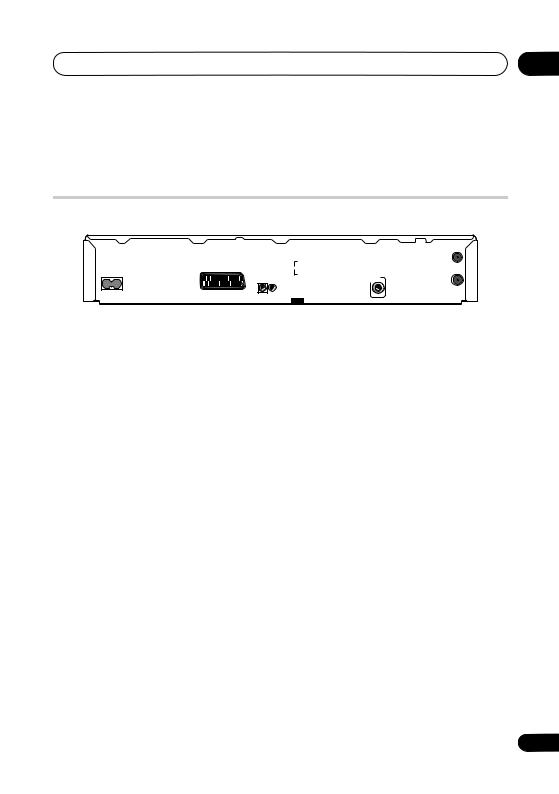
Rear panel connections
1 |
2 |
3 |
4 |
5 |
6 |
|
|
|
|
|
|
OUT |
|
|
|
|
|
ANTENNA |
|
|
|
|
R |
Y |
(DIGITAL) |
|
AV 2 (INPUT 1/DECODER) |
|
|
AUDIO |
|
IN |
|
AC IN |
|
|
|
|
|
|
|
|
|
L |
PB |
|
DIGITAL |
|
|
|
|
|
OUT |
AUDIO OUT |
IN |
|
|
|
PR |
|
IN |
AV 1 (RGB) – TV |
G-LINK |
|
|
|
|
ANTENNA |
CONTROL |
S-VIDEO |
VIDEO |
COMPONENT |
|
COAXIAL |
|
|
|
|
OUTPUT |
VIDEO OUT |
|
|
7 |
8 |
9 |
10 |
1AV1(RGB)-TV AV connector
Audio/video output SCART-type AV connector for connecting to a TV or other equipment with a SCART connector. The video output is switchable between video, S- Video and RGB. See page AV1 Out on
page 125 for how to set this up.
2AV2(INPUT 1/DECODER) AV connector
Audio/video input/output SCART-type AV connector for connecting to a VCR, or other equipment with a SCART connector. The input accepts video, S-Video and RGB. See AV2/L1 In on page 126 for how to set this up.
3OUTPUT
Stereo analog audio, video and S-Video outputs for connection to a TV or AV amplifier/receiver.
4 COMPONENT VIDEO OUT
A high-quality video output for connecting to a TV or monitor with a component video input.
5 ANTENNA (DIGITAL) IN/OUT
Connect your DTV antenna to the ANTENNA (DIGITAL) IN jack. The signal is passed through to the ANTENNA (DIGITAL) OUT jack for connection to your TV.
6 ANTENNA IN (RF IN)/OUT
Connect your TV antenna to the ANTENNA (RF IN) jack. The signal is passed through to the ANTENNA OUT jack for connection to your TV.
7AC IN – Power inlet
8CONTROL IN
Use to control this recorder from the remote sensor of another Pioneer component with a CONTROL OUT terminal and bearing the Pioneer mark. Connect the CONTROL OUT of the other component to the CONTROL IN of this recorder using a miniplug cord.
9 G-LINK™
Use to connect the supplied G-LINK™ cable
to enable GUIDE Plus+® to control an external satellite receiver, etc.
10 DIGITAL AUDIO OUT
Coaxial digital audio jack for connecting to an AV amplifier/receiver, Dolby Digital/DTS/ MPEG decoder or other equipment with a digital input.
15
En
02 Connecting up
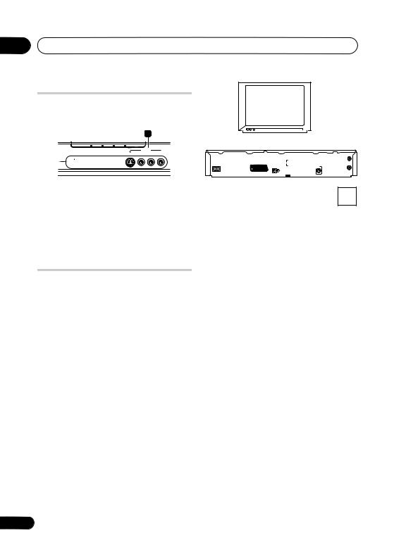
Front panel connections
On the front panel a flip-down cover hides more connections.
11
A.TV |
D.TV |
DivX |
PLTV |
TV |
INPUT 2
 AUDIO
AUDIO 
S-VIDEO VIDEO L(MONO) R
|
|
|
|
|
ANTENNA |
|
|
|
R |
Y |
(DIGITAL) |
AV 2 (INPUT 1/DECODER) |
|
|
AUDIO |
|
IN |
AC IN |
|
|
|
|
|
|
|
|
L |
PB |
|
|
|
|
|
|
OUT |
IN |
|
|
|
PR |
|
AV 1 (RGB) – TV |
G-LINK |
|
|
|
|
CONTROL |
S-VIDEO |
VIDEO |
COMPONENT |
|
|
|
|
|
OUTPUT |
VIDEO OUT |
|
|
OUT |
DIGITAL |
|
AUDIO OUT |
|
|
IN |
COAXIAL |
ANTENNA |
11 INPUT 2
Audio/video input (stereo analog audio; composite and S-Video video), especially suitable for camcorders, game consoles, portable audio, etc.
Connecting a TV antenna
This recorder has separate built-in TV tuners for terrestrial digital and terrestrial analog TV broadcasts.
If you are ready to receive digital broadcasts now, use the longer of the supplied RF antenna cables to connect the output of your antenna to the ANTENNA (DIGITAL) IN connector. Next use the short supplied RF antenna cable and connect it between the
ANTENNA (DIGITAL) OUT and ANTENNA (RF IN) connectors. Lastly, connect the recorder to your TV from the ANTENNA (RF OUT) connector.
Antenna wall outlet
If your area is not yet served with terrestrial digital services, connect your antenna’s output to the ANTENNA (RF IN) connector using one of the supplied RF antenna cables. Next, connect the recorder to your TV from the ANTENNA (RF OUT) connector.
TV |
|
|
|
|
|
|
OUT |
|
|
|
|
|
ANTENNA |
|
|
|
|
R |
Y |
(DIGITAL) |
|
AV 2 (INPUT 1/DECODER) |
|
|
AUDIO |
|
IN |
|
AC IN |
|
|
|
|
|
|
|
|
|
L |
PB |
|
DIGITAL |
|
|
|
|
|
OUT |
AUDIO OUT |
IN |
|
|
|
PR |
|
IN |
AV 1 (RGB) – TV |
G-LINK |
|
|
|
|
ANTENNA |
CONTROL |
S-VIDEO |
VIDEO |
COMPONENT |
|
COAXIAL |
|
|
|
|
OUTPUT |
VIDEO OUT |
|
|
Antenna wall outlet
We strongly recommend using an outdoor antenna for better broadcast picture quailty.
16
En

Connecting up |
02 |
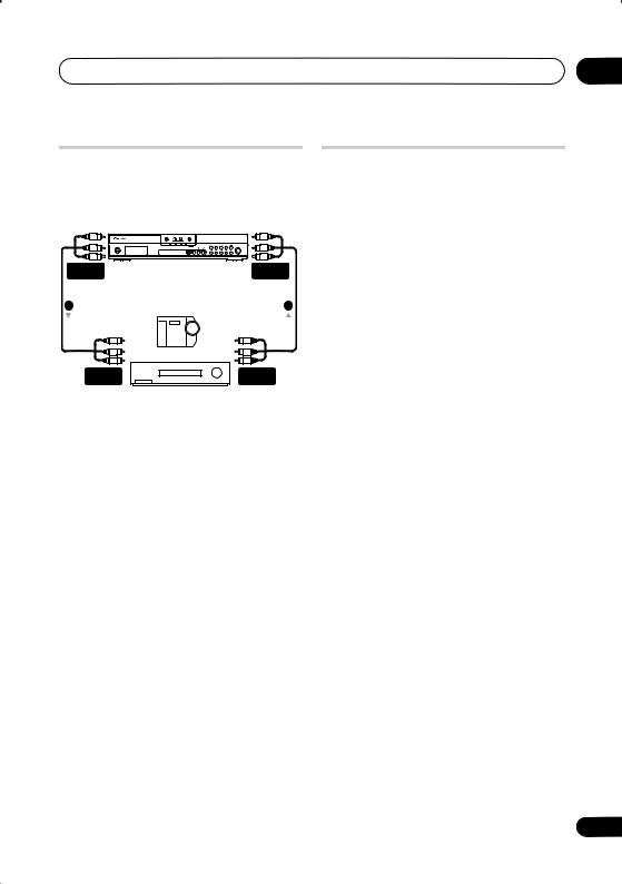
Easy connections
The setup described below is a basic setup that allows you to watch and record TV programs, and play discs. Other types of connections are explained starting on the following page.
 Important
•These connections use SCART cables (not supplied). If your TV (or VCR) does not have a SCART connection, if you want to use the supplied audio/video cable, see Using the supplied audio/video cable on page 18.
•The AV1(RGB)-TV AV connector can output ordinary (composite), S-Video or RGB video, plus stereo analog audio. The AV2(INPUT 1/DECODER) connector accepts ordinary, S- Video and RGB video input, as well as stereo analog audio. See AV1 Out on page 125 and AV2/L1 In on page 126 for how to set them up.
•Before making or changing any rear panel connections, make sure that all components are switched off and unplugged from the wall outlet.
SCART AV |
CONNECTOR |
2 |
TV |
|
|
|
|
|
|
OUT |
|
|
|
|
|
ANTENNA |
|
|
|
|
R |
Y |
(DIGITAL) |
|
AV 2 (INPUT 1/DECODER) |
|
|
AUDIO |
|
IN |
|
AC IN |
|
|
|
|
|
|
|
|
|
L |
PB |
|
DIGITAL |
|
|
|
|
|
OUT |
AUDIO OUT |
IN |
|
|
|
PR |
|
IN |
AV 1 (RGB) – TV |
G-LINK |
|
|
|
|
ANTENNA |
CONTROL |
S-VIDEO |
VIDEO |
COMPONENT |
|
COAXIAL |
|
|
|
|
OUTPUT |
VIDEO OUT |
|
|
To recorder's antenna input
3 |
2 |
|
SCART AV |
||
|
||
CONNECTOR |
|
|
|
ANTENNA |
|
|
OUT |
VCR
ANTENNA
IN
1
Antenna/cable TV wall outlet
1Connect your TV antenna to the recorder and TV.
See Connecting a TV antenna on page 16 for details.
•If you want to incorporate a VCR in your setup, connect it before the recorder (i.e., between the antenna wall outlet and the antenna input on the recorder).
2Use a SCART cable (not supplied) to connect the AV1(RGB)-TV AV connector on this recorder to the SCART AV connector on your TV.
3Use another SCART cable to connect the AV2(INPUT 1/DECODER) AV connector to a SCART AV connector on your VCR.
Tip
•This recorder has a ‘through’ function which allows you to record a TV program from the built-in TV tuner in this recorder while watching a video playing on your VCR (To use this feature when the recorder is in standby, Power Save must be set to Off—see Power Save on page 121).
17
En

02 Connecting up
Using other types of audio/ video output
If you can’t use the SCART AV connector to connect your TV to this recorder, there are standard audio/video output jacks, as well as an S-Video and component video output.
Using the supplied audio/video cable
AUDIO |
INPUT |
VIDEO |
INPUT |
TV |
2 |
|
|
|
|
OUT |
|
|
|
ANTENNA |
|
|
|
|
R |
Y |
(DIGITAL) |
|
AV 2 (INPUT 1/DECODER) |
|
AUDIO |
|
IN |
|
AC IN |
|
|
|
|
|
|
|
L |
PB |
|
DIGITAL |
|
|
|
|
OUT |
AUDIO OUT |
IN |
|
|
PR |
|
IN |
AV 1 (RGB) – TV |
|
|
|
|
ANTENNA |
CONTROL G-LINK |
S-VIDEO |
VIDEO |
COMPONENT |
|
COAXIAL |
1 |
|
OUTPUT |
VIDEO OUT |
|
|
|
|
|
|
|
1Connect the VIDEO OUTPUT jack to a video input on your TV.
Use the yellow jack of the supplied audio/ video cable for the video connection.
2Connect the AUDIO OUTPUT jacks to the corresponding audio inputs on your TV.
Use the red and white jacks of the supplied audio/video cable for the audio connection. Make sure you match up the left and right outputs with their corresponding inputs for correct stereo sound.
18
Using the S-Video or component video output
COMPONENT |
|
|
|
|
|
|
VIDEO INPUT |
|
|
|
|
|
|
|
|
|
|
|
|
S-VIDEO |
AUDIO |
|
|
|
|
|
INPUT |
|
|
|
|
|
|
|
INPUT |
|
|
|
|
|
|
2 |
TV |
|
|
|
|
1 |
|
|
|
|
|
||
|
|
|
|
|
|
OUT |
|
|
|
|
|
ANTENNA |
|
|
|
|
R |
Y |
(DIGITAL) |
|
AC IN |
AV 2 (INPUT 1/DECODER) |
|
AUDIO |
|
IN |
|
|
|
|
L |
PB |
|
DIGITAL |
|
|
|
|
|
OUT |
AUDIO OUT |
|
IN |
|
|
PR |
|
IN |
|
AV 1 (RGB) – TV |
|
|
|
|
ANTENNA |
|
CONTROL G-LINK |
S-VIDEO |
VIDEO |
COMPONENT |
|
COAXIAL |
|
|
|
OUTPUT |
VIDEO OUT |
|
|
1 Connect the S-Video or component video output to a similar input on your TV.
For an S-Video connection, use an S-Video cable (not supplied) to connect the S-VIDEO OUTPUT jack to an S-Video input on your TV.
For a component video connection, use a component video cable (not supplied) to connect the COMPONENT VIDEO OUT jacks to a component video input on your TV.
See also Component Video Out on page 125 for how to set up the component video output for use with a progressive scancompatible TV.
2 Connect the AUDIO OUTPUT jacks to the corresponding audio inputs on your TV.
You can use the supplied audio/video cable, leaving the yellow video plug disconnected. Make sure you match up the left and right outputs with their corresponding inputs for correct stereo sound.
En

Connecting up |
02 |
Connecting to a cable box or satellite receiver
If you have a cable box or satellite receiver with a built-in decoder, connect it to this recorder and your TV as shown on the
following page.1 If you are using a separate decoder box for your cable/satellite TV, set up following the instructions on the next page.
Using the setup on this page you can:
•Record any channel by selecting it on the cable box or satellite receiver.
•Change channels and set timer recordings on the external receiver using the GUIDE Plus+® system (via the G-LINK™ cable, and after setting up).
 Important
SCART AV
CONNECTOR
2
TV
|
|
|
|
|
OUT |
|
|
|
|
ANTENNA |
|
|
|
R |
Y |
(DIGITAL) |
|
AV 2 (INPUT 1/DECODER) |
|
AUDIO |
|
IN |
|
AC IN |
|
|
|
|
|
|
|
L |
PB |
|
DIGITAL |
|
|
|
|
OUT |
AUDIO OUT |
IN |
|
|
PR |
|
IN |
AV 1 (RGB) – TV |
|
|
|
|
ANTENNA |
CONTROL G-LINK |
S-VIDEO |
VIDEO |
COMPONENT |
|
COAXIAL |
|
|
OUTPUT |
VIDEO OUT |
|
|
To recorder's antenna input
4
SCART AV |
3 |
|
CONNECTOR |
||
|
ANTENNA
OUT
Cable/Satellite
receiver ANTENNA IN
1
Satellite dish/ antenna/cable TV
•Do not connect this recorder to your TV ‘through’ your VCR, satellite receiver or other component. Always connect each component directly to your TV or AV amplifier/receiver.
•When using the GUIDE Plus+ system to make a timer recording from an external receiver, make sure that the external receiver is switched on.
wall outlet
1Connect RF antenna cables as shown.
See Connecting a TV antenna on page 16 for more on RF antenna connections, including from this recorder to your TV.
2Use a SCART cable (not supplied) to connect the AV1(RGB)-TV AV connector to a SCART AV connector on your TV.
This enables you to watch discs.
3Use another SCART cable to connect the AV2(INPUT 1/DECODER) AV connector to a SCART AV connector on your cable box/satellite receiver.
This enables you to record scrambled TV channels.
 Note
Note
1 The diagram shows SCART video connections, but you can alternatively use any of the other audio/video connections.
19
En

02 Connecting up
4 Plug the supplied G-LINK™ cable to the G-LINK™ jack.
This enables you to control the tuner in the
external receiver using the GUIDE Plus+® system.
Position the IR transmitter end of the G- LINK™ cable so that the IR receiver on your cable/satellite receiver will pick up the control signals (see diagram).
|
|
|
|
ANT |
|
|
R |
Y |
(DIG |
AV 2 (INPUT 1/DECODER) |
|
AUDIO |
|
|
|
|
L |
PB |
|
IN |
|
|
PR |
|
AV 1 (RGB) – TV |
|
|
|
|
CONTROL G-LINK |
S-VIDEO |
VIDEO |
COMPONENT |
|
|
|
OUTPUT |
VIDEO OUT |
|
G-LINK cable
See the manual that came with your cable/ satellite receiver if you’re not sure where the IR receiver is on the front panel.
Alternatively, experiment with the remote control, operating it from very close range until you find the place where the receiver responds.
 Tip
Tip
•This recorder has a ‘through’ function which allows you to record a TV program from the built-in TV tuner in this recorder while watching a video playing on your VCR (To use this feature when the recorder is in standby, Power Save must be set to Off—see Power Save on page 121).
Connecting an external decoder box (1)
If you have an external, dedicated decoder box for your satellite or cable TV system, use the setup described on this page. See the previous page for how to connect the G- LINK™ cable.
20
 Important
•Do not connect your decoder box directly to this recorder.
•Information from the decoder (for example, relating to pay TV services), is only viewable when this recorder is off (in standby).
•For timer recording to work properly on this recorder, the VCR/satellite receiver/ cable box must also be switched on during recording.
•It is not possible to watch one TV program and record another using this setup.
SCART AV
CONNECTOR
4
TV
|
|
|
|
|
|
OUT |
|
|
|
|
|
ANTENNA |
|
|
|
|
R |
Y |
(DIGITAL) |
|
AV 2 (INPUT 1/DECODER) |
|
|
AUDIO |
|
IN |
|
AC IN |
|
|
|
|
|
|
|
|
|
L |
PB |
|
DIGITAL |
|
|
|
|
|
OUT |
AUDIO OUT |
IN |
|
|
|
PR |
|
IN |
AV 1 (RGB) – TV |
G-LINK |
|
|
|
|
ANTENNA |
CONTROL |
S-VIDEO |
VIDEO |
COMPONENT |
|
COAXIAL |
|
|
|
|
OUTPUT |
VIDEO OUT |
|
|
|
|
3 |
SCART AV |
2 |
SCART AV |
CONNECTOR |
|
CONNECTOR |
Decoder |
VCR/Satellite receiver |
|
|
/Cable box |
ANTENNA |
|
|
IN |
1
Antenna/cable TV wall outlet
1Connect the cable from the antenna/ cable TV outlet to the antenna input on your VCR/satellite receiver/cable box.
2Use a SCART cable (not supplied) to connect your decoder to your VCR/ satellite receiver/cable box.
En
Connecting up |
02 |
See the manual for your decoder box for more detailed instructions.
3 Use a SCART cable to connect your VCR/satellite receiver/cable box to the AV2(INPUT 1/DECODER) AV connector on this recorder.
SCART AV
CONNECTOR
2
TV
4 Use a SCART cable to connect the AV1(RGB)-TV AV connector to your TV.
Connecting an external decoder box (2)
If you only have a decoder, connect it to this recorder and your TV as shown on this
page.1
Using the setup on this page you can:
•Record scrambled channels received using the recorder’s built-in analog TV tuner.
|
|
|
|
|
|
OUT |
|
|
|
|
|
ANTENNA |
|
|
|
|
R |
Y |
(DIGITAL) |
|
AV 2 (INPUT 1/DECODER) |
|
|
AUDIO |
|
IN |
|
AC IN |
|
|
|
|
|
|
|
|
|
L |
PB |
|
DIGITAL |
|
|
|
|
|
OUT |
AUDIO OUT |
IN |
|
|
|
PR |
|
IN |
AV 1 (RGB) – TV |
G-LINK |
|
|
|
|
ANTENNA |
CONTROL |
S-VIDEO |
VIDEO |
COMPONENT |
|
COAXIAL |
|
|
|
|
OUTPUT |
VIDEO OUT |
|
|
3
SCART AV
 CONNECTOR
Decoder
1 Connect your TV antenna to the recorder and TV.
See Connecting a TV antenna on page 16 for details.
 Important
•Do not connect this recorder ‘through’ your VCR, satellite receiver or cable box. Always connect each component directly to your TV or AV amplifier/ receiver.
This enables you to watch and record TV channels.
2Use a SCART cable (not supplied) to connect the AV1(RGB)-TV AV connector to a SCART AV connector on your TV.
This enables you to watch discs.
3Use another SCART cable to connect the AV2(INPUT 1/DECODER) AV connector to a SCART AV connector on your decoder box.
This enables you to record scrambled TV channels.
 Note
Note
1 In order to use this setup, you will need to make the following settings from the Initial Setup menu:
•Set the AV2/L1 In setting to Decoder from the Initial Setup menu (see AV2/L1 In on page 126).
•From the Manual CH Setting screen, set the Decoder setting for the scrambled channels to On (see Manual CH Setting on page 124).
21
En

02 Connecting up
Connecting to an AV amplifier/receiver
To enjoy multichannel surround sound you need to connect this recorder to an AV amplifier/receiver using the digital coaxial output.
In addition to a digital connection, we recommend also connecting using the stereo analog connection for compatibility with all discs and sources.
You’ll probably also want to connect a video output to your AV amplifier/receiver. Use the ordinary video output (as shown here), or the S-Video output.
 Important
•Noise may be output from your speakers if the recorder is not set up to work with your AV amplifier/receiver properly (see Audio Out on page 127).
|
|
|
|
|
VIDEO |
|
|
|
|
|
IN |
TV |
|
|
|
|
4 |
|
|
|
|
|
|
AUDIO/VIDEO |
VIDEO |
|
|
|
|
OUT |
|
|
|
||
IN |
|
|
DIGITAL |
||
|
|
|
|
||
|
|
|
|
|
IN |
|
|
|
|
|
2 |
3 |
|
|
|
AV amp/ |
|
|
|
|
|
receiver |
|
|
|
|
|
|
OUT |
|
|
|
|
ANTENNA |
|
|
|
R |
Y |
(DIGITAL) |
|
AV 2 (INPUT 1/DECODER) |
|
AUDIO |
|
IN |
|
AC IN |
|
|
|
|
|
|
|
L |
PB |
|
DIGITAL |
|
|
|
|
OUT |
AUDIO OUT |
IN |
|
|
PR |
|
IN |
AV 1 (RGB) – TV |
|
|
|
|
ANTENNA |
CONTROL G-LINK |
S-VIDEO |
VIDEO |
COMPONENT |
|
COAXIAL |
|
|
OUTPUT |
VIDEO OUT |
|
|
1 Connect your TV antenna to the recorder and TV.
See Connecting a TV antenna on page 16 for details.
This enables you to watch and record TV channels.
2Connect the DIGITAL OUT COAXIAL jack on this recorder to a coaxial digital input on your AV amplifier/receiver.
This enables you to listen to multichannel surround sound.
3Connect the analog AUDIO OUTPUT and VIDEO OUTPUT jacks on this recorder to an analog audio and video input on your AV amplifier/receiver.
4Connect the AV amplifier/receiver’s video output to a video input on your TV.
 Important
•When watching D.TV only linear PCM audio is output from the coaxial digital out jack.
•Do not connect this recorder to your TV ‘through’ your VCR using A/V cables. Always connect it directly to your TV.
22
En
Connecting up
Connecting other AV sources
Connecting a VCR or analog camcorder
– +
AUDIO/VIDEO |
AUDIO/VIDEO |
OUTPUT |
INPUT |
(Rear panel) |
(Front panel) |
02
Plugging in
After checking all the connections, plug in the recorder.
• Use the supplied power cable to connect this recorder to a power outlet.
1 |
2 |
|
Analog camcorder |
AUDIO/VIDEO |
AUDIO/VIDEO |
INPUT |
OUTPUT |
|
VCR |
1Connect a set of audio and video inputs of your VCR or camcorder to a set of outputs on this recorder.
This enables you to record from this recorder to your VCR or camcorder.
•You can use standard video or S-Video cables for the video connection.
•Alternatively, you can use the
AV2(INPUT 1/DECODER) SCART connector for audio/video input and output with just one SCART cable.
2Connect a set of audio and video outputs of your VCR or camcorder to a set of inputs on this recorder.
This enables you to record tapes from your VCR or camcorder.
•You can use standard video or S-Video cables for the video connection.
•The front panel connections make convenient connections for a camcorder input.
23
En
03 Controls and displays
Chapter 3
Controls and displays
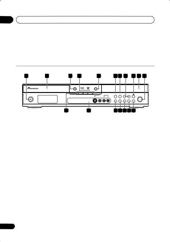
Front panel
1 |
2 |
3 |
4 |
|
|
|
5 |
6 |
7 |
8 |
9 |
10 11 |
|
|
|
|
OPEN/CLOSE |
|
|
HDD/DVD |
|
|
|
|
|
|
|
|
|
|
A.TV |
D.TV |
DivX |
PLTV |
|
|
|
|
CH + |
|
|
|
|
|
|
|
|
|
INPUT 2 |
|
|
– |
|
|
|
STANDBY/ON |
|
|
|
|
|
|
|
|
|
|
|
REC |
|
STANDBY/ON |
|
|
|
|
S-VIDEO |
AUDIO |
R |
|
|
|
REC |
||
|
|
|
|
|
|
VIDEO L(MONO) |
|
|
|
|
|
||
|
|
|
|
|
|
|
|
HELP |
A.TV/D.TV |
INPUT |
ONE TOUCH |
PAUSE |
|
|
|
|
|
|
|
|
|
SELECT |
COPY |
LIVE TV |
|
||
12
1 STANDBY/ON
Press to switch the recorder on/into standby.
2Disc tray
3OPEN/CLOSE
Press to open/close the disc tray.
4 HDD / DVD indicators
Indicator lights blue when the hard disk (HDD) is selected; orange when the DVD drive is selected.
5 HDD/DVD
Press to switch between HDD and DVD for recording and playback.
6
Press to start or restart playback.
7
Press to stop playback.
8 CH +/–
Use to change channels, skip chapters/ tracks, etc.
9 (STOP REC)
Press to stop recording.
13 |
14 15 16 17 18 |
10Front panel display and IR remote sensor
See Display on page 25 for details.
11REC
Press to start recording. Press repeatedly to set the recording time in 30 minute blocks.
12A.TV indicator
Lights when analog TV is selected.
D.TV indicator
Lights when digital TV is selected.
DivX indicator
Lights during DivX playback.
PLTV indicator
Lights during recording started using the Pause Live TV feature.
13Front panel inputs
See Front panel connections on page 16 for more information on these.
14 HELP
Press for help on how to use the current GUI screen.
24
En

Controls and displays |
03 |
15 A.TV / D.TV
Switches between analog TV antenna input and digital TV antenna input. The A.TV and D.TV indicators show which is selected.
16 INPUT SELECT
Press to change the input to use for recording.
17ONE TOUCH COPY (page 100) Press to start One Touch Copy of the currently playing title to DVD or the HDD.
18PAUSE LIVE TV (page 65)
Press to start recording the current TV channel, but with playback paused, effectively pausing the broadcast.
Display
1 |
2 |
3 |
4 |
5 |
|
|
L |
R |
P |
8 |
7 |
6 |
1
Lights during playback; blinks when playback is paused.
2
Lights when copying.
3
Lights during recording; blinks when recording is paused.
4 (page 66)
Lights when a timer recording has been set. (Indicator blinks if the timer has been set to DVD but there isn’t a recordable disc loaded, or the timer has been set to HDD but the HDD is not recordable.)
NTSC
Lights when the video output signal format is NTSC.

 (page 127)
Indicates which channels of a bilingual broadcast are recorded.
 (page 125)
Lights when the component video output is set to progressive scan.
VPS / PDC (page 66)
Lights when receiving a VPS/PDC broadcast during a VPS/PDC-enabled timer recording.
5Recording quality indicators (page 63)
XP
Lights when the recording mode is set to XP (best quality).
SP
Lights when the recording mode is set to SP (standard play).
LP / SLP
Lights when the recording mode is set to LP (long play) or SLP (super-long play).
EP / SEP
Lights when the recording mode is set to EP (extended play) or SEP (superextended play).
25
En

03 Controls and displays
MN
Lights when the recording mode is set to MN (manual recording level) mode.
6Character display
7R / RW
Lights when a recordable DVD-R or DVD-RW disc is loaded.
8PL (page 87)
Lights when a VR mode disc is loaded and the recorder is in Play List mode.
2 3 (page 132)
Shows the remote control mode (if nothing is displayed, the remote control mode is 1).
V
Lights when an unfinalized Video mode disc is loaded.
Remote control
|
|
|
|
|
|
2 PAUSE LIVE TV (page 65) |
|
STANDBY/ON |
|
HDD/DVD |
|
Press to start recording the current TV |
|
|
|
|
|
|||
1 |
|
|
|
|
11 |
channel, but with playback paused, |
|
PAUSE LIVE TV |
HOME MENU |
INFO |
12 |
||
2 |
|
|
|
|
effectively pausing the broadcast. |
|
TOP MENU |
|
|
|
13 |
||
|
|
|
|
|
||
3 |
DISC |
|
GUIDE |
14 |
3 DISC NAVIGATOR (page 77, 87) / TOP |
|
NAVIGATOR |
|
|||||
|
|
|
|
|||
4 |
|
|
|
|
|
MENU (page 74) |
|
CM |
ENTER |
CM |
|
Press to display the Disc Navigator screen, |
|
|
BACK |
SKIP |
|
|||
|
PAUSE |
|
RETURN/EDIT |
|
or the top menu if a DVD-Video or finalized |
|
5 |
REC |
PLAY |
|
STOP |
15 |
DVD-R/-RW (Video) disc is loaded. |
|
|
16 |
|
|||
6 |
|
|
|
|
4 / / / and ENTER |
|
|
STOP REC |
PREV |
|
NEXT |
|
|
|
|
|
|
|
17 |
Used to navigate all on-screen displays. |
|
|
|
CHANNEL |
|
|
Press ENTER to select the currently |
7 |
TIMER REC |
|
|
A.TV/D.TV |
|
highlighted option. |
|
|
|
|
18 |
||
8 |
/ |
/ |
HELP |
TV/DVD |
While watching D.TV press ENTER to |
|
REC MODE |
|
ONE TOUCH COPY |
19 |
|||
|
|
|
display the Channel List screen. |
|||
|
AUDIO SUBTITLE |
ANGLE INPUT SELECT |
20 |
|||
|
|
|
||||
9 |
|
|
|
|
21 |
CM BACK (commercial back) |
|
|
PLAY MODE |
MENU |
22 |
||
|
|
|
|
|
|
|
|
SHIFT |
CLEAR |
DISPLAY |
Press repeatedly to skip progressively |
|
10 |
|
23 |
backward through the audio or video |
|
|
|
TEXT |
|
|
|
OPENOPEN |
|
playing. |
|
|
|
|
CM SKIP (commercial skip) |
|
|
|
|
Press repeatedly to skip progressively |
1 |
STANDBY/ON |
|
|
forward through the audio or video |
Press to switch the recorder on/into standby. |
playing. |
|||
5 PAUSE
Press to pause playback or recording.
26
En

Controls and displays |
03 |
6 Recording controls (page 64)
REC
Press to start recording. Press repeatedly to set the recording time in blocks of 30 mins.
When the red action button is visible in a
GUIDE Plus+® screen, use for One- Button-Record.
STOP REC
Press to stop recording.
7Colour buttons
(RED, GREEN, YELLOW, BLUE)
Use when an EPG screen is displayed or when tuned to a data channel of a digital broadcast. The function of each button will be described on-screen, and changes depending on the screen being displayed.
TIMER REC (page 38)
Hold SHIFT and press to set a timer recording from the GUIDE Plus+® system.
A.TV / D.TV
Hold SHIFT and press to switch between analog TV antenna input and digital TV antenna input. The A.TV and D.TV indicators on the front panel show which is selected.
8(page 78)
Press to start reverse or forward scanning. Press again to change the speed.
(page 79)
While paused, press and hold to start slow-motion playback. Press repeatedly to change the playback speed.
While paused, press to advance a single frame in either direction.
When GUIDE Plus+® is displayed, use to display the previous/next day.
9Number buttons, CLEAR
Use the number buttons for track/ chapter/title selection; channel selection, and so on. The same buttons can also be used to enter names for titles, discs and so on.
Use CLEAR to clear an entry and start again.
REC MODE (page 63)
Hold SHIFT and press repeatedly to change the recording mode (picture quality).
AUDIO (page 62, 83)
Hold SHIFT and press to change the audio language or channel. (When the recorder is stopped, press to change the tuner audio.)
SUBTITLE (page 82)
Hold SHIFT and press to display/change the subtitles included in multilingual DVD-Video discs.
While watching D.TV, press to change the D.TV subtitles.
ANGLE (page 84)
Hold SHIFT and press to switch camera angles on discs with multi-angle scenes.
PLAY MODE (page 79)
Hold SHIFT and press to change the play mode (search, repeat, program play, etc.).
10SHIFT
Use to access functions on the remote printed in green.
11 HDD/DVD (page 64)
Press to select the hard disk (HDD) or DVD for recording and playback.
27
En

03 Controls and displays
12 INFO
While watching D.TV, press to display the information banner.
Press to see additional information for the highlighted item in the EPG.
13 HOME MENU
Press to display the Home Menu, from which you can navigate all the functions of the recorder.
14 GUIDE
Press to display the EPG screen; press again to exit.
15 RETURN/EXIT
Press to go back one level in the on-screen menu or display.
Also press to exit the MHEG application.
16 PLAY (page 72)
Press to start playback.
STOP (page 72)
Press to stop playback.
17CHANNEL +/– (page 60)
Press to change the channel of the builtin TV tuner.
PREV NEXT
Press to skip to the previous or next title/ chapter/track/folder; or to display the previous or next menu page.
When GUIDE Plus+® is displayed, use to display the previous/next page.
18HELP
Press for help on how to use the current GUI screen.
19TV/DVD
Press to switch between ‘TV mode’, in which you get the picture and sound from the TV’s tuner, and ‘DVD mode’, in which you get picture and sound from the recorder’s tuner (or an external input).
28
20ONE TOUCH COPY (page 100) Press to start One Touch Copy of the currently playing title to DVD or the HDD.
21INPUT SELECT (page 68)
Press to change the input to use for recording.
22 MENU (page 73)
Press to display the disc menu if a DVDVideo, finalized DVD-R/-RW or finalized DVD+R/+RW disc is loaded.
When in the GUIDE Plus+® system, use to jump directly to the Menu bar.
23DISPLAY (page 84) Displays/changes the on-screen information displays.
TEXT
Hold SHIFT and press to start the MHEG application display, if available, while watching a digital channel (UK only).
En

Getting started
Chapter 4
Getting started
Switching on and setting up
When you switch the recorder on for the first time, you can make several basic settings using the Setup Navigator feature. This takes you through setting the clock, the internal TV tuner and the video output.
If you’re using the recorder for the first time, we strongly recommend you use the Setup Navigator before starting to use the recorder.
1 Switch on your TV and set the video input to this recorder.
STANDBY/ON
2  Switch on the recorder.
When you switch on for the first time, your TV should display the Setup Navigator screen (If the Setup Navigator doesn’t appear, you can also access it from the Initial Setup menu; see page 121).
•If this recorder is connected to a compatible TV using a fully-wired 21-pin SCART cable, the recorder will take a few seconds to download country, TV screen size and language information. (Check the manual that came with your TV for compatibility information.)
04
ENTER |
|
|
3 |
|
Choose a language (then |
press ENTER). |
||
Initial |
Setup |
|
Basic |
|
Clock SettingLanguage |
Tuner |
|
Input Line System |
Video In/ O ut |
Power Save |
|
Audio In |
|
Help |
Audio O ut |
|
EPG Type Select |
Language |
|
Setup Navigator |
Recording |
|
|
Playback |
|
|
4 ENTER |
Start the Setup Navigator. |
|
Complete this setup before you start using your recorder.
Start
p Navigator Cancel
Please use the Initial Setup if you want to make more detailed settings.
•If you don’t want to use the Setup Navigator, press to select Cancel, then press ENTER to exit the Setup Navigator.
|
ENTER |
5 |
Select ‘Auto Scan’ to start |
scanning for D.TV channels.
•Select Do not set if you want to skip D.TV channel setup (because they have already been set up, for example), then skip to step 7 below.
29
En

04 Getting started
|
ENTER |
6 |
Select your country. |
The recorder starts scanning for new channels. After the scan is complete the recorder will let you know how many new channels were found.
•The country setting will apply to both the digital and analog TV tuners.
•The clock will also be set automatically here if D.TV channels are found.
•If no new channels were found a message appears asking if you want to scan again. Check the aerial connection before selecting Yes. (If you select No, skip to step 7 below.)
|
ENTER |
7 |
Select the analog TV (A.TV) |
Auto Channel Setting (‘Auto Scan’ or ‘Download from TV’), or ‘Do not set’.
Auto Channel Setting
AutoEnglishScan
Download from TV
p Navigator Do not Set
•Select Do not set if you want to skip channel setup (because they have already been set up, for example).
•You can only use the Download from TV feature if this recorder is connected to your TV using a fully-wired 21-pin SCART cable via the AV1(RGB)-TV connector, and if your TV supports this function (check your TV’s instruction manual for more details).
ENTER
•Select your country.
Country Selection
Country |
UK |
30
•Auto-tuning channels
The Auto Scan option automatically scans and sets the channel presets.
Tuning
32/99
Cancel
• Downloading channels from your TV
Use the Download from TV option to download all the channels that your TV is tuned to.
|
Downloading |
Pr 5 |
|
|
32/99 |
|
|
Cancel |
|
ENTER |
|
8 |
Select ‘Auto’ for automatic |
|
time setting, or ‘Manual’ to set the clock manually.
If the clock was already set from a D.TV channel in step 6, this step is skipped.
Clock Setting

 Auto
Auto
Manual
•Auto clock setting
Some TV channels broadcast time signals together with the program. This recorder can use these signals to set the clock automatically.
Set ‘Clock Set CH‘ to the channel preset number that broadcasts a time signal, then move the cursor down to ‘Start’ and press ENTER.
Auto Clock Setting |
|
|
|
Date |
–– |
/ |
–– / –––– |
Time |
–– |
: |
–– |
p Navigator |
|
|
Pr 1 |
Clock Set CH |
|
|
|
|
|
|
Start |
En
 Loading...