


DVH-3190
Table of contents
 Loading...
PIONEER CORPORATION 4-1, Meguro 1-chome, Meguro-ku, Tokyo 153-8654, Japan
PIONEER ELECTRONICS (USA) INC. P.O. Box 1760, Long Beach, CA 90801-1760, U.S.A.
PIONEER EUROPE NV Haven 1087, Keetberglaan 1, 9120 Melsele, Belgium
PIONEER ELECTRONICS ASIACENTRE PTE. LTD. 253 Alexandra Road, #04-01, Singapore 159936
PIONEER CORPORATION 2009
DVD RECEIVER
ORDER NO.
CRT4283
DVH-3150UB/XN/RC
DVH-3150UB
DVH-3150UB
DVH-3150UB
DVH-3150UB
DVH-3190UB
This service manual should be used together with the following manual(s):
Model No. Order No. Mech.Module Remarks
CX-3250 CRT4300 LS1 DVD Mech. Module : Circuit Descriptions, Mech. Descriptions, Disassembly
DTS and DTS Digital Out are registered trademartks and the DTS logos and Symbol are
trademarks of DTS, Inc.
Manufactured under license from Dolby Laboratories. Dolby, Pro Logic, and the double-D
symbol are trademarks of Dolby Laboratories.
/XN/RD
/XN/RI
/XN/CN5
/XN/ID
/XN/RC
For details, refer to "Important Check Points for Good Servicing".
K-ZZZ. JAN. 2009 Printed in Japan
1234
1234
C
D
F
A
B
E
SAFETY INFORMATION
Where in a manufacturer’s service documentation, for example in circuit diagrams or lists
of components, a symbol is used to indicate that a specific component shall be replaced only
by the component specified in that documentation for safety reasons, the following symbol shall
be used:
This service manual is intended for qualified service technicians; it is not meant for the casual do-it-yourselfer.
Qualified technicians have the necessary test equipment and tools, and have been trained to properly and safety repair
complex products such as those covered by this manual.
Improperly performed repairs can adversely affect the safety and reliability of the product and may void the warranty.
If you are not qualified to perform the repair of this product properly and safety, you should not risk trying to do so
and refer the repair to a qualified service technician.
CAUTION
Danger of explosion if battery is incorrectly replaced.
Replaced only with the same or equivalent type recommended by the manufacture.
Discord used batteries according to the manufacture's instructions.
CAUTION:
USE OF CONTROLS OR ADJUSTMENTS OR PERFORMANCE OF PROCEDURES OTHER THAN THOSE
SPECIFIED HEREIN MAY RESULT IN HAZARDOUS RADIATION EXPOSURE.
- Safety Precautions for those who Service this Unit.
When checking or adjusting the emitting power of the laser diode exercise caution in order to get safe, reliable
results.
Caution:
1. During repair or tests, minimum distance of 13 cm from the focus lens must be kept.
CAUTION
CLASS 1M INVISIBLE LASER RADIATION WHEN OPEN. DO NOT VIEW DIRECTLY WITH OPTICAL INSTRUMENTS
2. During repair or tests, do not view laser beam for 10 seconds or longer.
WARNING!
The AEL (accessible emission level )of the laser power output is less than CLASS 1
but the laser component is capable of emitting radiation exceeding the limit for
CLASS 1.
A specially instructed person should do servicing operation of the apparatus.
Laser diode characteristics
Wave length:
DVD:660 nm to 670 nm
CD:780 nm to 800 nm
Focus lens on Maximum output:
CD:6.26 mW(Emitting period :9 sec.)
DVD:1.27 mW (Emitting period : unlimited)
Additional Laser Caution
Transistors Q1103 and Q1104 in PCB drive the laser diodes for DVD and CD
respectively. When Q1103 or Q1104 is shorted between their terminals,
the laser diodes for DVD or CD will radiate beam. If the top cover is removed
with no disc loaded while such short-circuit is continued, the naked eyes may
be exposed to the laser beam.
2
DVH-3150UB/XN/RC
5678
56
7
8
C
D
F
A
B
E
[Important Check Points for Good Servicing]
In this manual, procedures that must be performed during repairs are marked with the below symbol.
Please be sure to confirm and follow these procedures.
1. Product safety
Please conform to product regulations (such as safety and radiation regulations), and maintain a safe servicing environment by
following the safety instructions described in this manual.
1 Use specified parts for repair.
Use genuine parts. Be sure to use important parts for safety.
2 Do not perform modifications without proper instructions.
Please follow the specified safety methods when modification(addition/change of parts) is required due to interferences such as
radio/TV interference and foreign noise.
3 Make sure the soldering of repaired locations is properly performed.
When you solder while repairing, please be sure that there are no cold solder and other debris.
Soldering should be finished with the proper quantity. (Refer to the example)
4 Make sure the screws are tightly fastened.
Please be sure that all screws are fastened, and that there are no loose screws.
5 Make sure each connectors are correctly inserted.
Please be sure that all connectors are inserted, and that there are no imperfect insertion.
6 Make sure the wiring cables are set to their original state.
Please replace the wiring and cables to the original state after repairs.
In addition, be sure that there are no pinched wires, etc.
7 Make sure screws and soldering scraps do not remain inside the product.
Please check that neither solder debris nor screws remain inside the product.
8 There should be no semi-broken wires, scratches, melting, etc. on the coating of the power cord.
Damaged power cords may lead to fire accidents, so please be sure that there are no damages.
If you find a damaged power cord, please exchange it with a suitable one.
9 There should be no spark traces or similar marks on the power plug.
When spark traces or similar marks are found on the power supply plug, please check the connection and advise on secure
connections and suitable usage. Please exchange the power cord if necessary.
a Safe environment should be secured during servicing.
When you perform repairs, please pay attention to static electricity, furniture, household articles, etc. in order to prevent injuries.
Please pay attention to your surroundings and repair safely.
2. Adjustments
To keep the original performance of the products, optimum adjustments and confirmation of characteristics within specification.
Adjustments should be performed in accordance with the procedures/instructions described in this manual.
4. Cleaning
For parts that require cleaning, such as optical pickups, tape deck heads, lenses and mirrors used in projection monitors, proper
cleaning should be performed to restore their performances.
3. Lubricants, Glues, and Replacement parts
Use grease and adhesives that are equal to the specified substance.
Make sure the proper amount is applied.
5. Shipping mode and Shipping screws
To protect products from damages or failures during transit, the shipping mode should be set or the shipping screws should be
installed before shipment. Please be sure to follow this method especially if it is specified in this manual.
DVH-3150UB/XN/RC
3

1234
1234
C
D
F
A
B
E
CONTENTS
SAFETY INFORMATION ..................................................................................................................................... 2
1. SERVICE PRECAUTIONS ............................................................................................................................... 5
1.1 SERVICE PRECAUTIONS......................................................................................................................... 5
1.2 NOTES ON SOLDERING .......................................................................................................................... 5
2. SPECIFICATIONS ............................................................................................................................................ 6
2.1 SPECIFICATIONS...................................................................................................................................... 6
2.2 DISC/CONTENT FORMAT ........................................................................................................................ 8
2.3 PANEL FACILITIES.................................................................................................................................. 10
2.4 CONNECTION DIAGRAM ....................................................................................................................... 16
3. BASIC ITEMS FOR SERVICE........................................................................................................................ 19
3.1 CHECK POINTS AFTER SERVICING..................................................................................................... 19
3.2 PCB LOCATIONS .................................................................................................................................... 20
3.3 JIGS LIST ................................................................................................................................................ 21
3.4 CLEANING............................................................................................................................................... 21
4. BLOCK DIAGRAM.......................................................................................................................................... 22
5. DIAGNOSIS.................................................................................................................................................... 27
5.1 OPERATIONAL FLOWCHART ................................................................................................................ 27
5.2 INSPECTION METHOD OF PICKUP UNIT............................................................................................. 28
5.3 DIAGNOSIS FLOWCHART...................................................................................................................... 31
5.4 ERROR CODE LIST................................................................................................................................ 58
5.5 CONNECTOR FUNCTION DESCRIPTION............................................................................................. 61
6. SERVICE MODE............................................................................................................................................ 62
6.1 DISPLAY TEST MODE ............................................................................................................................ 62
6.2 DVD TEST MODE.................................................................................................................................... 63
7. DISASSEMBLY............................................................................................................................................... 67
8. EACH SETTING AND ADJUSTMENT ........................................................................................................... 75
8.1 DVD ADJUSTMENT................................................................................................................................. 75
8.2 PCL OUTPUT CONFIRMATION.............................................................................................................. 82
9. EXPLODED VIEWS AND PARTS LIST.......................................................................................................... 84
9.1 PACKING ................................................................................................................................................. 84
9.2 EXTERIOR(1) .......................................................................................................................................... 86
9.3 EXTERIOR(2) .......................................................................................................................................... 88
9.4 DVD MECHANISM MODULE .................................................................................................................. 90
10. SCHEMATIC DIAGRAM ............................................................................................................................... 94
10.1 TUNER AMP UNIT(GUIDE PAGE) ........................................................................................................ 94
10.2 KEYBOARD UNIT................................................................................................................................ 100
10.3 DVD CORE UNIT(GUIDE PAGE)......................................................................................................... 102
10.4 CONNECT PCB................................................................................................................................... 108
10.5 WAVEFORMS...................................................................................................................................... 109
11. PCB CONNECTION DIAGRAM ................................................................................................................. 112
11.1 TUNER AMP UNIT............................................................................................................................... 112
11.2 KEYBOARD UNIT................................................................................................................................ 116
11.3 DVD CORE UNIT................................................................................................................................. 118
11.4 CONNECT PCB................................................................................................................................... 120
12. ELECTRICAL PARTS LIST ........................................................................................................................ 122
4
DVH-3150UB/XN/RC

5678
56
7
8
C
D
F
A
B
E
1. You should conform to the regulations governing the product (safety, radio and noise, and other regulations),
and should keep the safety during servicing by following the safety instructions described in this manual.
2. Be careful in handling ICs. Some ICs such as MOS type are so fragile that they can be damaged by electrostatic
induction.
3. Before disassembling the unit, be sure to turn off the power. Unplugging and plugging the connectors during
power-on mode may damage the ICs inside the unit.
4. To protect the pickup unit from electrostatic discharge during servicing, take an appropriate treatment
(shorting-solder) by referring to "the DISASSEMBLY" .
5. After replacing the pickup unit, be sure to skew adjustment.
6. During disassembly, be sure to turn the power off since an internal IC might be destroyed when a connector
is plugged or unplugged.
7. ICs (IC1011, 1021) and the heat sink becomes hot areas. Be careful not be burn yourself.
8. Mechanism cover(Sheet : CNN2525) is NOT reusable. If you removed it, please replace it with the new one.
For environmental protection, lead-free solder is used on the printed circuit boards mounted in this unit.
Be sure to use lead-free solder and a soldering iron that can meet specifications for use with lead-free solders for repairs
accompanied by reworking of soldering.
Compared with conventional eutectic solders, lead-free solders have higher melting points, by approximately 40 C.
Therefore, for lead-free soldering, the tip temperature of a soldering iron must be set to around 373 C in general, although
the temperature depends on the heat capacity of the PC board on which reworking is required and the weight of the tip of
the soldering iron.
Compared with eutectic solders, lead-free solders have higher bond strengths but slower wetting times and higher melting
temperatures (hard to melt/easy to harden).
The following lead-free solders are available as service parts:
Parts numbers of lead-free solder:
GYP1006 1.0 in dia.
GYP1007 0.6 in dia.
GYP1008 0.3 in dia.
1. SERVICE PRECAUTIONS
1.1 SERVICE PRECAUTIONS
1.2 NOTES ON SOLDERING
DVH-3150UB/XN/RC
5
1234
1234
C
D
F
A
B
E
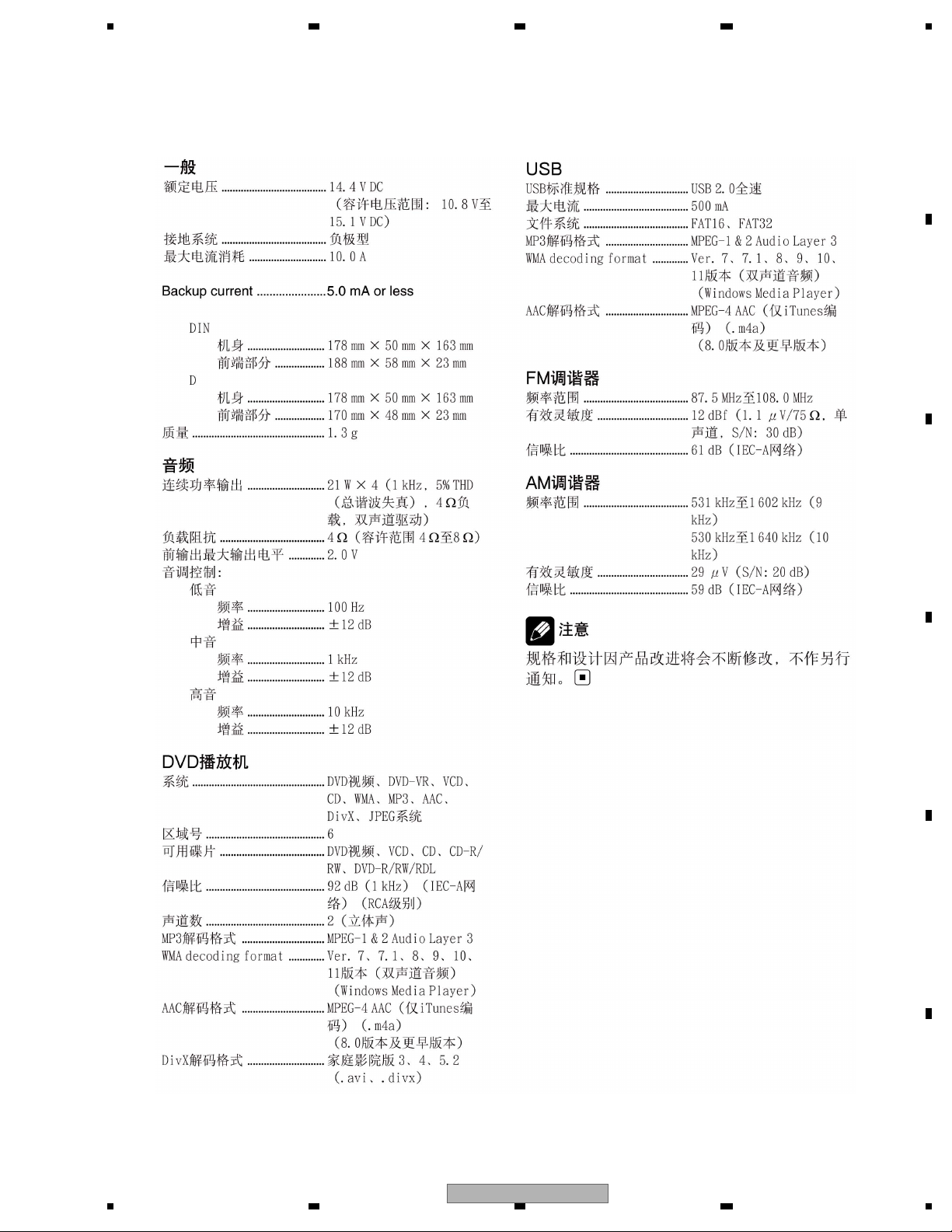
2. SPECIFICATIONS
Dimensions (W × H × D):
DIN
Chassis.................. 178 mm × 50 mm × 163
mm
Nose....................... 188 mm × 58 mm × 23 mm
D
Chassis.................. 178 mm × 50 mm × 163
mm
Nose........................ 170 mm × 48 mm × 23 mm
Weight ..................................... 1.3 kg
Audio
Maximum power output ...... 50 W × 4
Continuous power output .. 22 W × 4 (50 Hz to 15 000
Hz, 5 % THD, 4
load, both
channels driven)
Load impedance ................... 4
(4 to 8 allowable)
Preout max output level ...... 2.0 V
Tone controls:
Bass
Frequency.............. 100 Hz
Gain ......................... ±12 dB
Mid
Frequency.............. 1 kHz
Gain ......................... ±12 dB
Treble
Frequency.............. 10 kHz
Gain ......................... ±12 dB
DVD Player
System ..................................... DVD video, DVD-VR, Video
CD, CD, WMA, MP3, AAC,
DivX, JPEG system
Region number:
for Middle East Asian and South African models
...................................... 2
for Southeast Asian models
...................................... 3
for South American and Oceanian models
...................................... 4
Usable discs .......................... DVD video, Video CD, CD,
CD-R/RW, DVD-R/RW/RDL
Frequency response............. 5 Hz to 44 000 Hz (with DVD,
at sampling frequency 96
kHz)
Signal-to-noise ratio............. 96 dB (1 kHz) (IEC -A net-
work) (RCA level)
Number of channels ............ 2 (stereo)
MP3 decoding format ..........MPEG-1 & 2 Audio Layer 3
WMA decoding format ........ Ver. 7,7.1, 8, 9, 10, 11 (2ch
audio)
(Windows Media Player)
AAC decoding format........... MPEG-4 AAC (iTunes en-
coded only) (.m4a)
(Ver. 8.0 and earlier)
DivX decoding format...........Home Theater Ver. 3, 4, 5.2
(.avi, .divx)
USB
USB standard specification
............................................... USB 2.0 full speed
Maximum current supply ....500 mA
File system.............................. FAT16, FAT32
MP3 decoding format ..........MPEG-1 & 2 Audio Layer 3
WMA decoding format ........ Ver. 7,7.1, 8, 9, 10, 11 (2ch
audio)
(Windows Media Player)
AAC decoding format........... MPEG-4 AAC (iTunes en-
coded only) (.m4a)
(Ver. 8.0 and earlier)
FM tuner
Frequency range.....................87.5 MHz to 108.0 MHz
Usable sensitivity.................. 9 dB f (0.8 μV/75
, mono,
S/N: 30 dB)
Signal-to-noise ratio............. 72 dB (IEC-A network)
AM tuner
Frequency range................... 531 kHz to 1 602 kHz (9 kHz)
530 kHz to 1 640 kHz (10
kHz)
Usable sensitivity.................. 25 μV (S/N: 20 dB)
Signal-to-noise ratio............. 62 dB (IEC-A network)
Infrared remote control
Wavelength............................. 945 nm
Output ......................................typ; 10 mw/sr per Infrared
LED
Note
Specifications and the design are subject to modifications without notice due to improvements.
General
Rated power source..............14.4 V DC
(allowable voltage range:
12.0 V to 14.4 V DC)
Grounding system................. Negative type
Max. current consumption
...............................................10.0 A
Backup current ......................5.0 mA or less
for India models
...................................... 5
DVH-3150UB/XN/RC, DVH-3150UB/XN/RD, DVH-3150UB/XN/RI, DVH-3190UB/XN/ID
RC, RD, RI
2.1 SPECIFICATIONS
6
DVH-3150UB/XN/RC
5678
56
7
8
C
D
F
A
B
E
DVH-3150UB/XN/CN5
DVH-3150UB/XN/RC
7
1234
1234
C
D
F
A
B
E
2.2 DISC/CONTENT FORMAT
Handling guideline of discs
and player
• Use only discs featuring any of following
logos.
DVD video
Video CD
CD
• Use only normal, round discs. If you insert
irregular, non-round, shaped discs they
may jam in the DVD player or not play properly.
• Check all discs for cracks, scratches or
warping before playing. Discs that have
cracks, scratches or are warped may not
play properly. Do not use such discs.
• Avoid touching the recorded (non-printed)
surface when handling the disc.
• Store discs in their cases when not in use.
• Keep discs out of direct sunlight and do
not expose the discs to high temperatures.
• Do not attach labels, write on or apply chemicals to the surface of the discs.
• To clean a disc, wipe the disc with a soft
cloth outward from the center.
• If the heater is used in cold weather, condensation may form on components inside
the DVD player. Condensation may cause
the DVD player to not operate properly. If
you think that condensation is a problem
turn off the DVD player for an hour or so to
allow it to dry out and wipe any damp discs
with a soft cloth to remove the moisture.
• Road shocks may interrupt disc
playback.
8
DVH-3150UB/XN/RC
5678
56
7
8
C
D
F
A
B
E
is a trademark of DVD Format/Logo Licensing Corporation.
DVH-3150UB/XN/RC
9
1234
1234
C
D
F
A
B
E
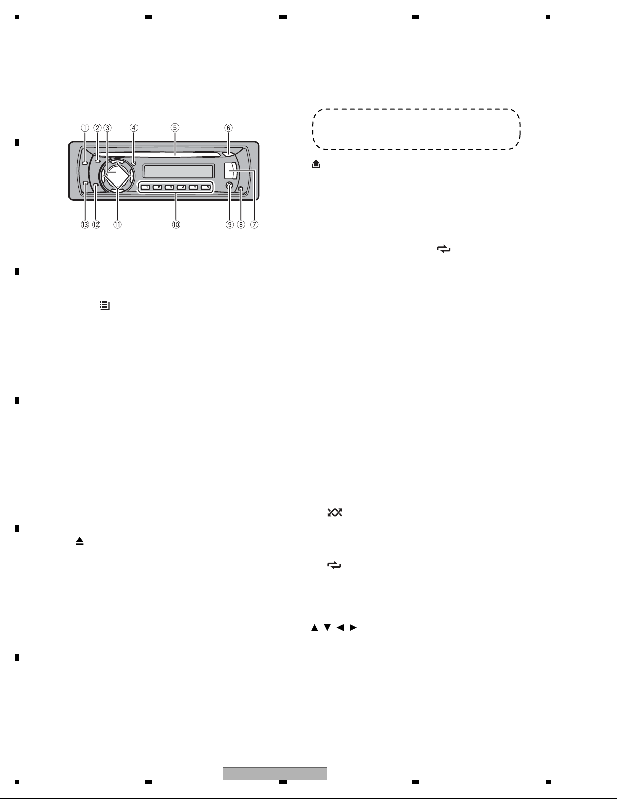
2.3 PANEL FACILITIES
What ’s what
Head unit
1 SRC/OFF button
This unit is turned on by selecting a source.
Press to cycle through all the available
sources.
2 LIST/
button
Press to display the track title list, folder list
or file list depending on the source.
• This button is not effective when tuner is
selected as a source.
3 MULTI-CONTROL
Turn to increase or decrease the volume.
Press to select a menu on the DVD menu.
Also used for controlling functions.
4 CLOCK button
Press to change to the clock display.
Press and hold to turn the display indication
and button illumination off or on.
5 Disc loading slot
Insert a disc to play.
6
(eject) button
Press to eject a disc.
7 USB port
Use to connect a USB audio player/USB
memory.
• When connecting, open up the USB connector lid.
• Use a USB cable to connect the USB
audio player/USB memory to the USB
port. Since the USB audio player/USB
memory is projected forward from the
unit, it is dangerous to connect directly.
Pioneer CD-U50E USB cable is also available. For details, consult your dealer.
8
(detach) button
Press to remove the front panel from the
head unit.
9 AUX input jack (3.5 mm stereo jack)
Use to connect an auxiliary device.
a 1/S.Rtrv/DVD MENU to 6/
/ANGLE
buttons
Press for preset tuning. Also used for controlling functions.
• 1/S.Rtrv/DVD MENU
— Press to controlS.RTRV (advanced
sound retriever).
— Press to return to the top menu dur-
ing DVD playback.
— Press and hold to switch the DVD
menu on or off during DVD playback.
• 2/PAUSE
— Press to controlPAUSE (pause).
• 3/BOOKMARK
— Press to control the resume playback
(bookmark) function during DVD playback.
• 4/AUDIO
— Press to change the audio language/
audio system during DVD playback.
• 5/
/SUB TITLE
— Press to controlRANDOM (random).
— Press to change the subtitle language
during DVD playback.
• 6/
/ANGLE
— Press to controlREPEAT (repeat).
— Press to change the viewing angle
during DVD playback.
b
/ / / buttons
Press to perform manual seek tuning, fast
forward, reverse and title/folder/chapter/
track/file search controls.
Press to select a menu on the DVD menu.
Also used for controlling functions.
• When operating menus
RC, RD, RI, ID
10
DVH-3150UB/XN/RC

5678
56
7
8
C
D
F
A
B
E
— Pressing is the same function as
turning MULTI-CONTROL right.
— Pressing
is the same function as
turning MULTI-CONTROL left.
— Pressing
is the same function as
pressing DISP/BACK/SCRL.
— Pressing and holding
is the same
function as pressing and holding
DISP/BACK/SCRL .
— Pressing
is the same function as
pressing MULTI-CONTROL .
• When operating lists
— Pressing
is the same function as
turning MULTI-CONTROL left.
— Pressing
is the same function as
turning MULTI-CONTROL right.
— Pressing
is the same function as
pressing DISP/BACK/SCRL .
— Pressing and holding
is the same
function as pressing and holding
DISP/BACK/SCRL .
— Pressing
is the same function as
pressing MULTI-CONTROL .
— Pressing and holding
is the same
function as pressing and holding
MULTI-CONTROL.
c DISP/BACK/SCRL button
Press to select different displays.
Press and hold to scroll through the text information.
Press to return to the previous display when
operating the menu.
Press and hold to return to the main menu
when operating the menu.
d BAND/ESC button
Press to select among three FM bands and
one AM band.
Press to return to the ordinary display when
operating the menu.
Note
The function ofDISP/BACK/SCRL is different depending on the setting of the display connection
(refer toSetting the display connection on or off).
DVH-3150UB/XN/RC
11
1234
1234
C
D
F
A
B
E
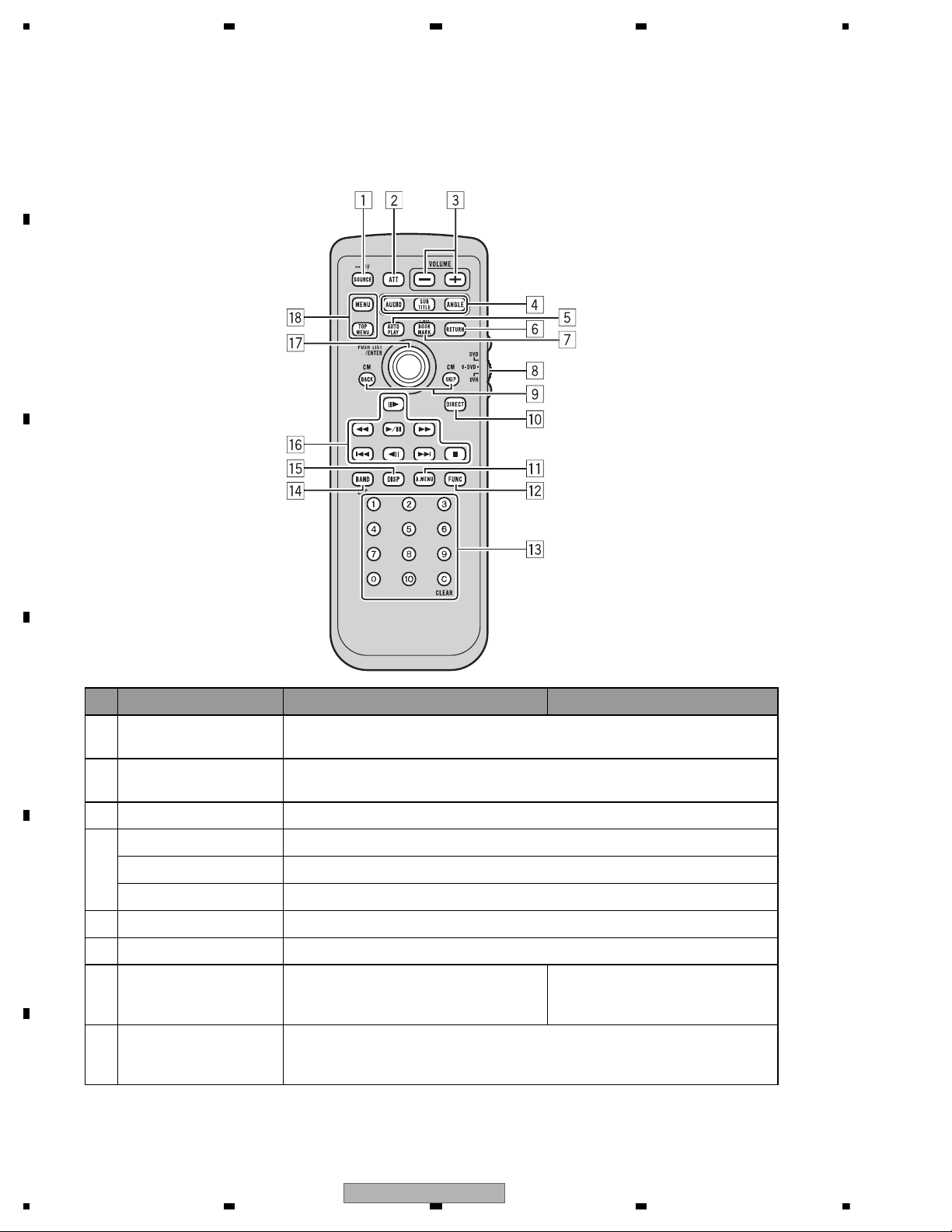
Remote control
Button names DVH mode DVD and S-DVDmode
1 SOURCE button
Press to cycle through all the available sources. Press and hold to turn the source
off.
2ATTbutton
Press to quickly lower the volume level by about 90%. Press once more to return
to the original volume level.
3 VOLUME buttons Press to increase or decrease the volume.
4
AUDIO button Press to change the audio language/audio system during DVD playback.
SUBTITLE button Press to change the subtitle language during DVD playback.
ANGLE button Press to change the viewing angle during DVD playback.
5 AUTO PLAY button Press to turn the DVD auto-playback function on or off.
6 RETURN button Press to display the PBC (playback control) menu during PBC playback.
7 BOOKMARK button
Press to operate the preprogrammed functions for each source. (Refer to Using the
PGM button.)
Press to turn the bookmark function
on or off. For details, refer toResume
playback (Bookmark).
8
Remote control operation
mode switch
Switch the operation mode between DVD, S-DVDand DVH modes. Normally, set
to DVH. For details, refer to Using the remote control operation mode switch on
the next page.
12
DVH-3150UB/XN/RC
5678
56
7
8
C
D
F
A
B
E
CM BACK / CM SKIP
9
buttons
10 DIRECT button Press to select channels directly. Not used.
11 A.MENU button Press to select various sound quality controls.
12 FUNC button Press to select functions.
0 to 10 buttons, CLEAR
13
button
14 BAND button
15 DISP button
PLAY/PAUSE (
ton
REVERSE (
FORWARD(
PREVIOUS(
16
NEXT(
) button Press to go to the next track (chapter).
) but-
) button Press to perform fast reverse.
) button Press to perform fast forward.
) button Press to return to the previous track (chapter).
Press to skip progressively backward/forward through the video playing.
Press0 to 9 to input numbers. Buttons 1
to 6 can operate the preset tuning for the
tuner or disc changing for multi-CD
players. Press CLEAR to clear the input
numbers.
Press to select among three FM bands
and one AM band and to cancel control
modes of functions.
Press to turn the information display on or off when the video is displayed.
Depending on the selected source, pressing this button can switch the display indication.
Press to switch sequentially between playback and pause.
Press to select a menu item on a
video CD featuring PBC (playback
control).
Press to switch between media file
types. (Refer to Switching
the media file type.)
Press to move ahead one frame at a time during DVD/VideoCD playback. Press
STEP (
STOP(
Move the thumb pad
17
Click the thumb pad
MENU button Press to display the DVD menu during DVD playback.
18
TOP MENU button Press to return to the top menu during DVD playback.
/ ) buttons
Using the remote control operation
mode switch
and hold for one second to activate slow playback.
If a DVD-VR disc contains a still image, press
switch to the next image or video.
Functions are the same as MULTI-CON-
TROL on the head unit.
Move to operate fast forward, reverse and
track search controls. Also used for controlling functions.
Click to display the track title list, folder
list or file list depending on the source.
the head unit’s buttons and the remote control
can control this unit.
There are three remote control operation
modes on the remote control. If you want to
operate this unit by remote control, turn the
mode switch to DVH mode. In this case, both
DVH mode operation
When operating this unit by remote control,
the mode is normally switched toDVH.
while displaying a still image to
.kcabyalppotsotsserP.desutoNnottub)
Move to select a menu on the DVD
menu.
Click to select a menu on the DVD
menu.
DVH-3150UB/XN/RC
13

1234
1234
C
D
F
A
B
E
• The thumb pad on the remote control can
perform the same operations as
MULTI-CONTROL on the head unit.
DVD mode operation
If you switch the mode to DVD , the thumb pad
and 0 to 10 operations are changed for the
DVD player.
•
When you want to operate the follow-
ing functions, switch the mode to DVD:
• When operating the DVD menu by using
the thumb pad. (Refer toOperating the DVD
menu.)
• When operating the PBC menu by using 0
to 10. (Refer toPBC playback.)
• When specifying title or track by using 0 to
10. (Refer toSpecifying title and
Specifying track.)
• When operating the DVD setup menu by
using the thumb pad. (Refer toSetting up
the DVD player.)
S-DVD mode operation
When using the remote control with this unit,
there is no need to switch toS-DVD mode.
Display indication
1 Main display section
Displays band, frequency, elapsed playback
time and other settings.
• Tuner
Band and frequency are displayed.
• Built-in DVD player, USB
Elapsed playback time and literal information are displayed.
2
(artist) indicator
Appears when the disc (track) artist name is
displayed on the main display section.
3
(disc) indicator
Appears when the disc (album) name is displayed on the main display section.
4
(song) indicator
Appears when the track (song) name is displayed on the main display section.
Appears when playable file is displayed during viewing the file name list of disc and a
USB storage device.
5
indicator
Appears when an upper tier of folder or
menu exists.
6
(list) indicator
Appears when operating list function.
7
indicator
Appears when a lower tier of folder or menu
exists.
8 LOC indicator
Appears when local seek tuning is on.
9
LOUD (loudness) indicator
Appears when loudness is on.
a
(stereo) indicator
Appears when the selected frequency is
being broadcast in stereo.
b
(repeat) indicator
Shows when track repeat is turned on.
Also, shows when folder repeat is on.
c
(random) indicator
Shows when random play is on.
Note
When you set the display connection (refer to Setting the display connection on or off )
to on, the indicators of 2 to 7 do not appear.
14
DVH-3150UB/XN/RC
5678
56
7
8
C
D
F
A
B
E
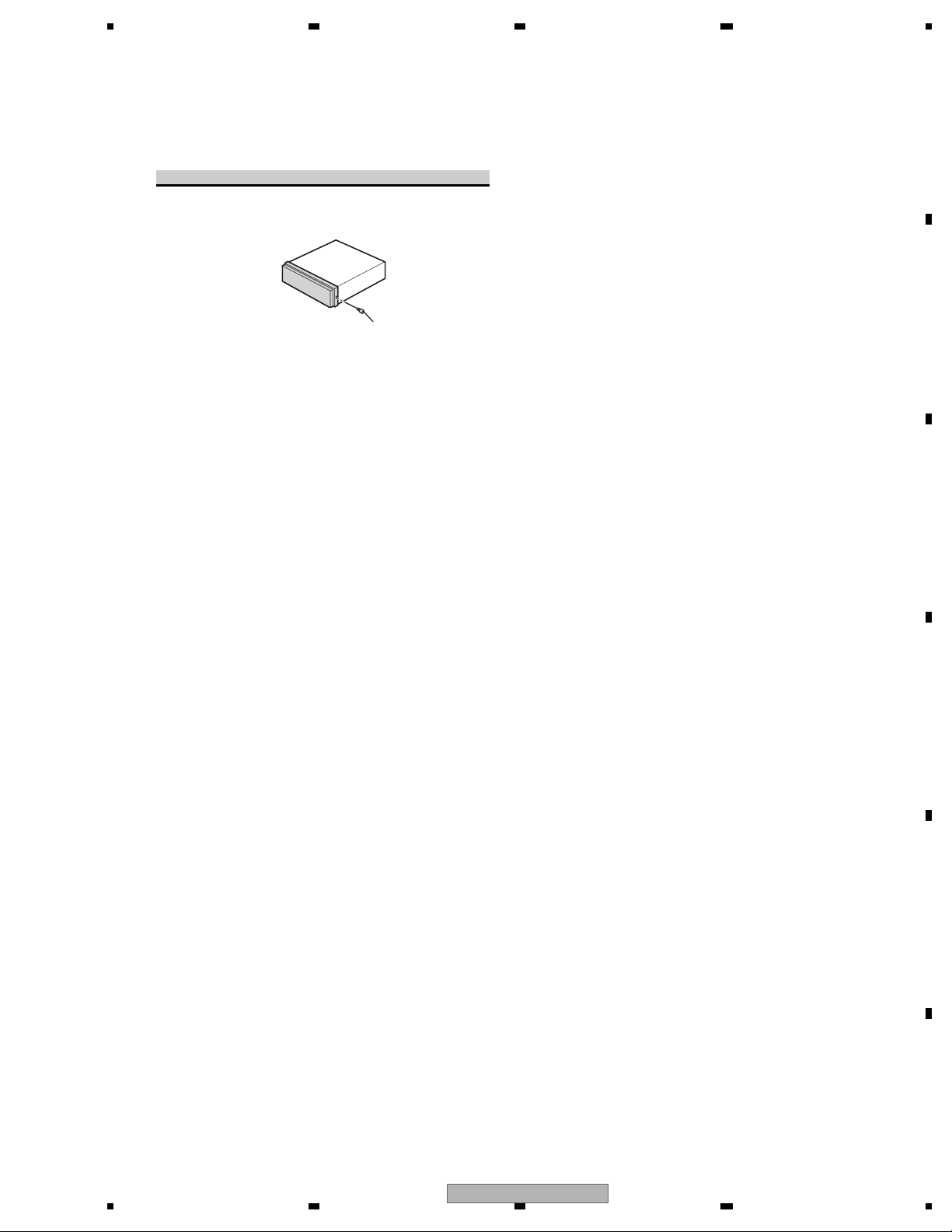
Fastening the front panel
If you do not plan to detach the front panel, the
front panel can be fastened with supplied screw.
Screw
CXX2204
DVH-3150UB/XN/RC
15
1234
1234
C
D
F
A
B
E
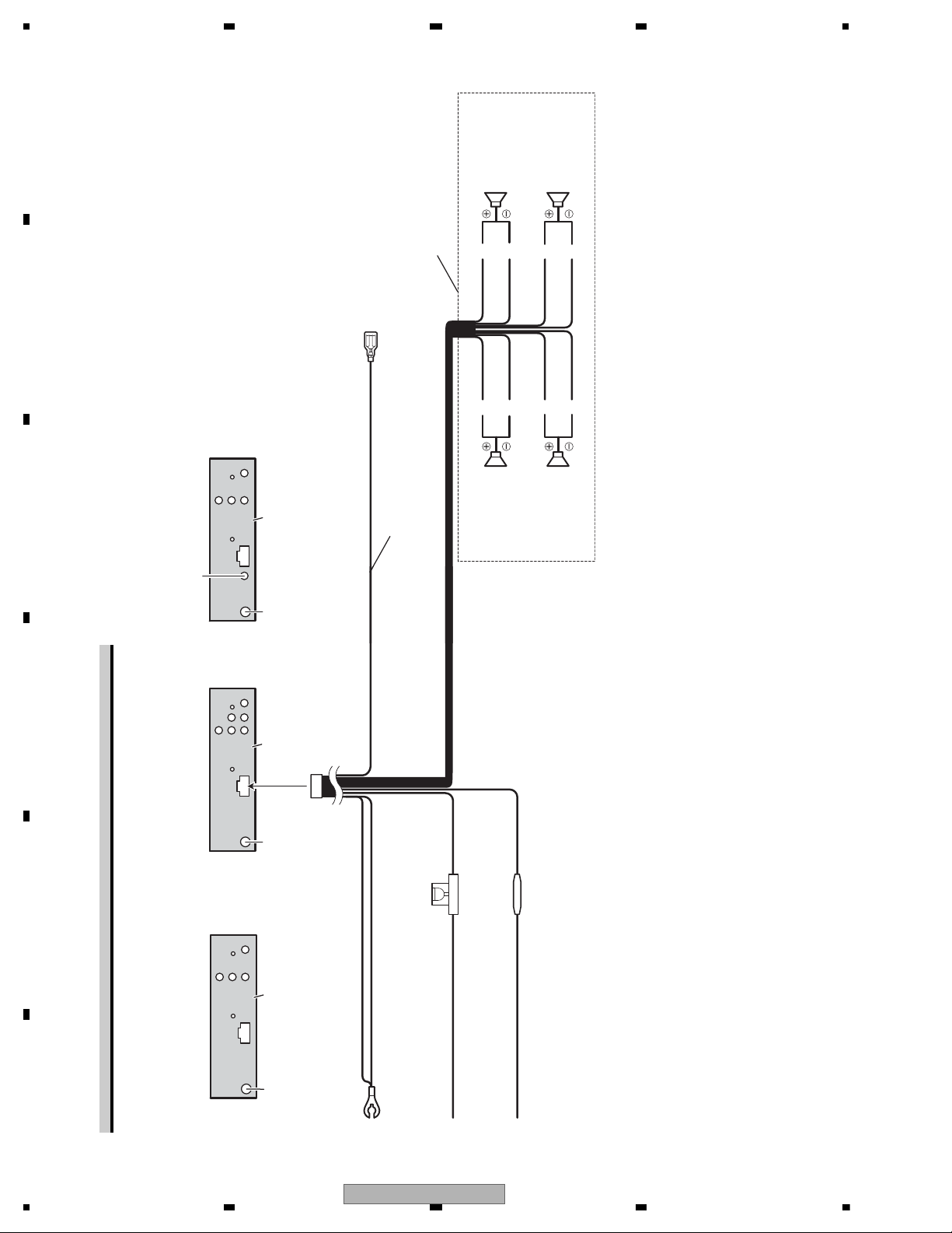
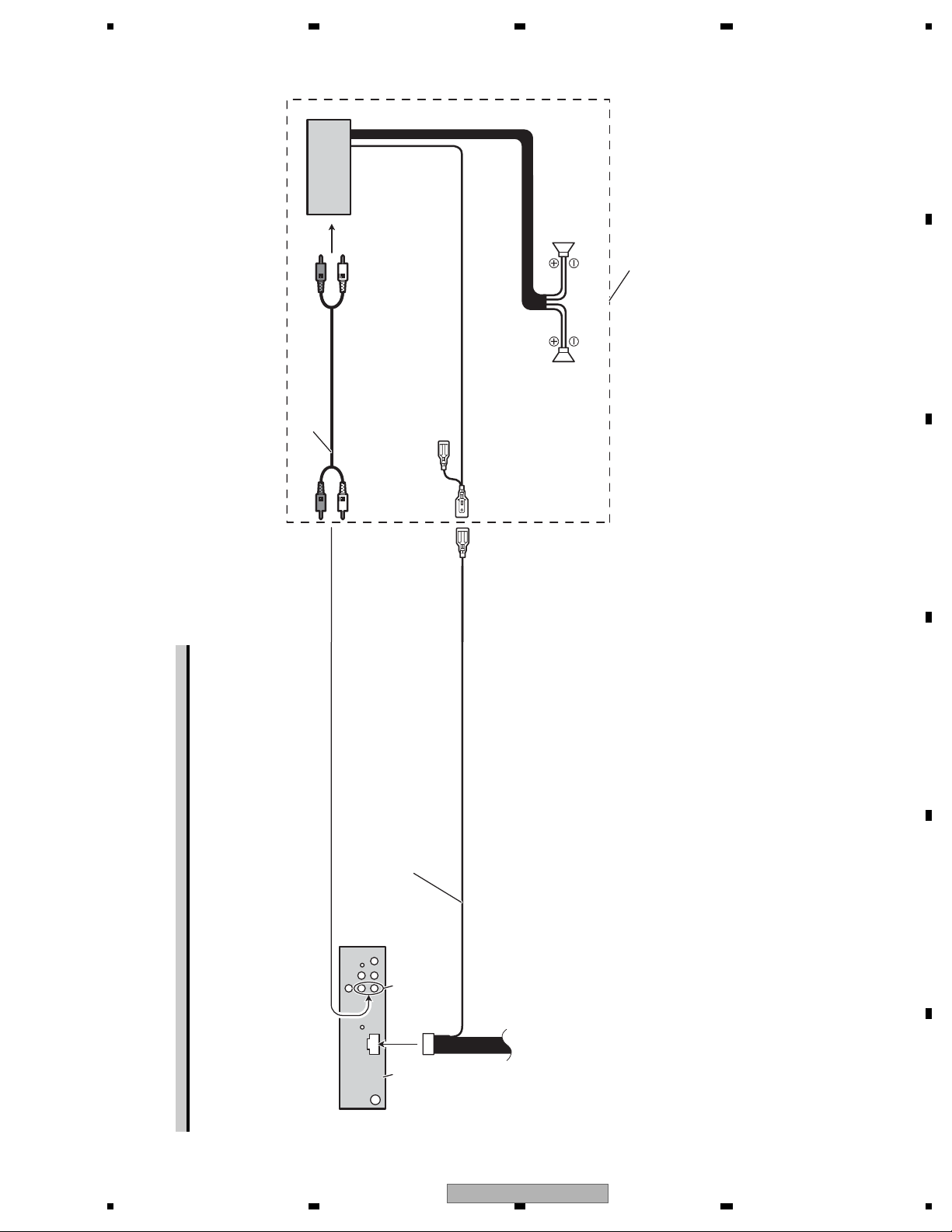
2.4 CONNECTION DIAGRAM
Power cable connection
BCa
m
Antenna jack
Front speakerFront speaker
This productAntenna jack
Wired remote input
Hard-wired remote control adaptor can be
connected (sold separately).
This product
Antenna jack
RD, RI RC, ID CN5
RighttfeL
Rear speaker
With a 2 speaker system, do not connect
anything to the speaker leads that are not
connected to speakers.
Gray/blackWhite/black
White Gray
Blue/white
Connect to system control terminal of the power
amp or auto-antenna relay control terminal
(max. 300 mA 12 V DC).
(
This product
Green Violet
Green/black Violet/black
Rear speaker
16
DVH-3150UB/XN/RC
Fuse (10 A)
Black (chassis ground)
Connect to a clean, paint-free metal location.
Fuse resistor
Yellow
Connect to the constant 12 V supply terminal.
Red
Connect to terminal controlled by ignition switch (12 V DC).
5678
56
7
8
C
D
F
A
B
E
Power amp (sold
separately)
Rear speakerRear speaker
Perform these connections when
using the optional amplifier.
Connect with RCA cables
(sold separately)
System remote control
Blue/white
Connect to system control terminal of the power
amp or auto-antenna relay control terminal
(max. 300 mA 12 V DC).
* The connection method is the same though figure is RC, ID model.
This product Rear output
Connecting to separately sold power amp
DVH-3150UB/XN/RC
17
1234
1234
C
D
F
A
B
E
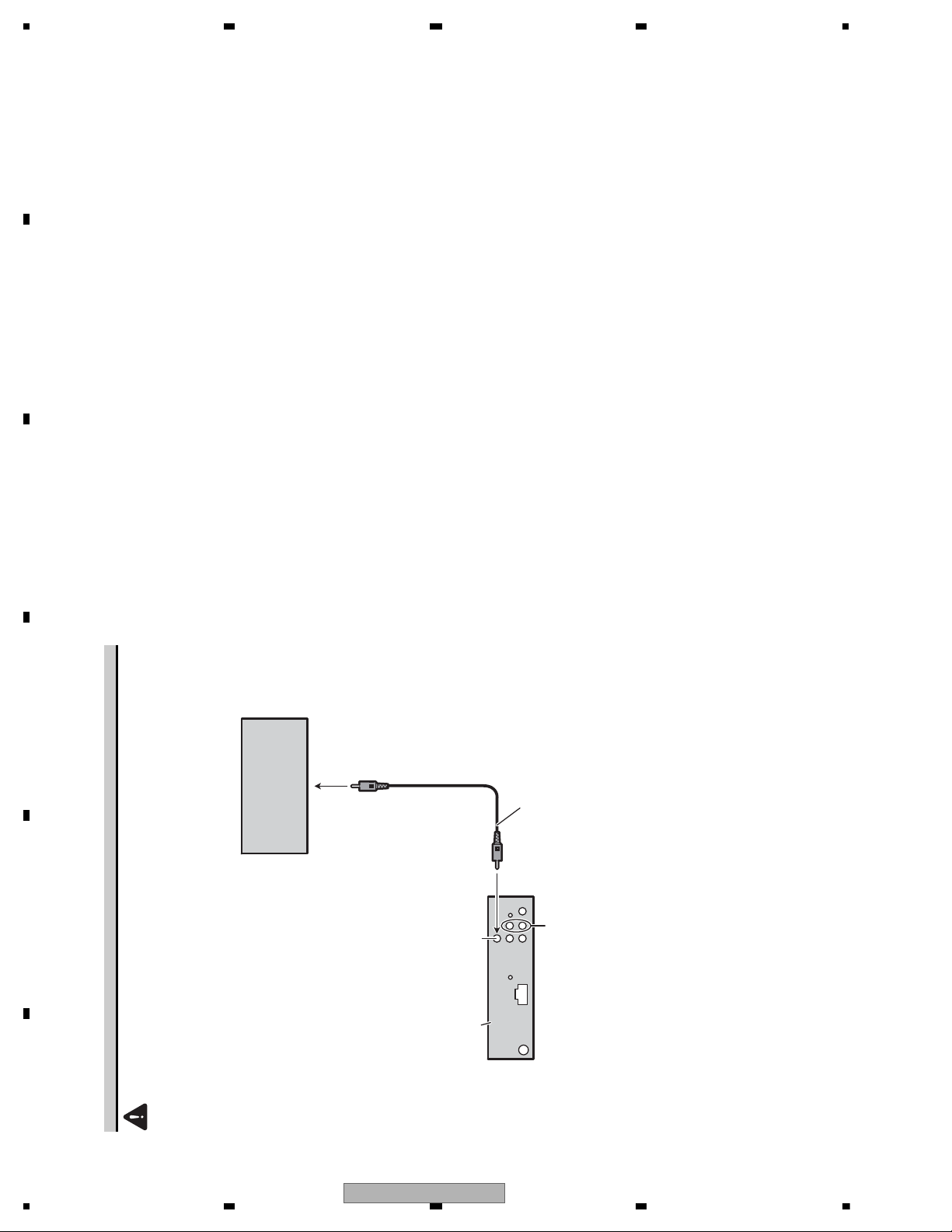
When using a display connected video outputs
WARNING
Never install the display in a location where it is visible to the driver while driving.
Display with
RCA input jacks
To video input
RCA cable
(supplied)
1.5 m
This product
Video output
(VIDEO OUTPUT)
Audio input
(AUDIO INPUT)
Input the sound from
external devices (e.g. TV).
* The connection method is the same though figure is RC, ID model.
18
DVH-3150UB/XN/RC
5678
56
7
8
C
D
F
A
B
E
To keep the product quality after servicing, please confirm following check points.
No. Procedures Item to be confirmed
1 Confirm whether the customer complain has
been solved.
If the customer complain occurs with the
specific media, use it for the operation check.
The customer complain must not be
reappeared.
Display, video, audio and operations must be
normal.
2 DVD Measure playback error rates at the
innermost and outermost tracks by using the
test mode with the following disc.
DVD test disc (TDV-582)
Deterioration of mecha-drive can be
checked.
The error rate must be less than the
threshold value.
(Refer to the chapter of DIAGNOSIS for the
threshold value.)
3 DVD Play back a DVD.
(Menu operation; Title/chapter search)
Display, video, audio and operations must be
normal.
4 CD Play back a CD.
(Track search)
Display, audio and operations must be
normal.
5 FM/AM tuner Check FM/AM tuner action.
(Seek, Preset)
Switch band to check both FM and AM.
Display, audio and operations must be
normal.
6 Check whether no disc is inside the product. The media used for the operating check must
be ejected.
7 Appearance check No scratches or dirt on its appearance after
receiving it for service.
For check items concerning image and voice, please refer to the followings:
Check items concerning image Check items concerning voice
Block-noise Distortion
Crosscut noise Noise
Dot noise Low volume
Distorted image (Image skip) High volume
Low brightness Changes in level
Too bright Pause of sound
Color fading
Partial discoloration
3. BASIC ITEMS FOR SERVICE
3.1 CHECK POINTS AFTER SERVICING
DVH-3150UB/XN/RC
19
1234
1234
C
D
F
A
B
E
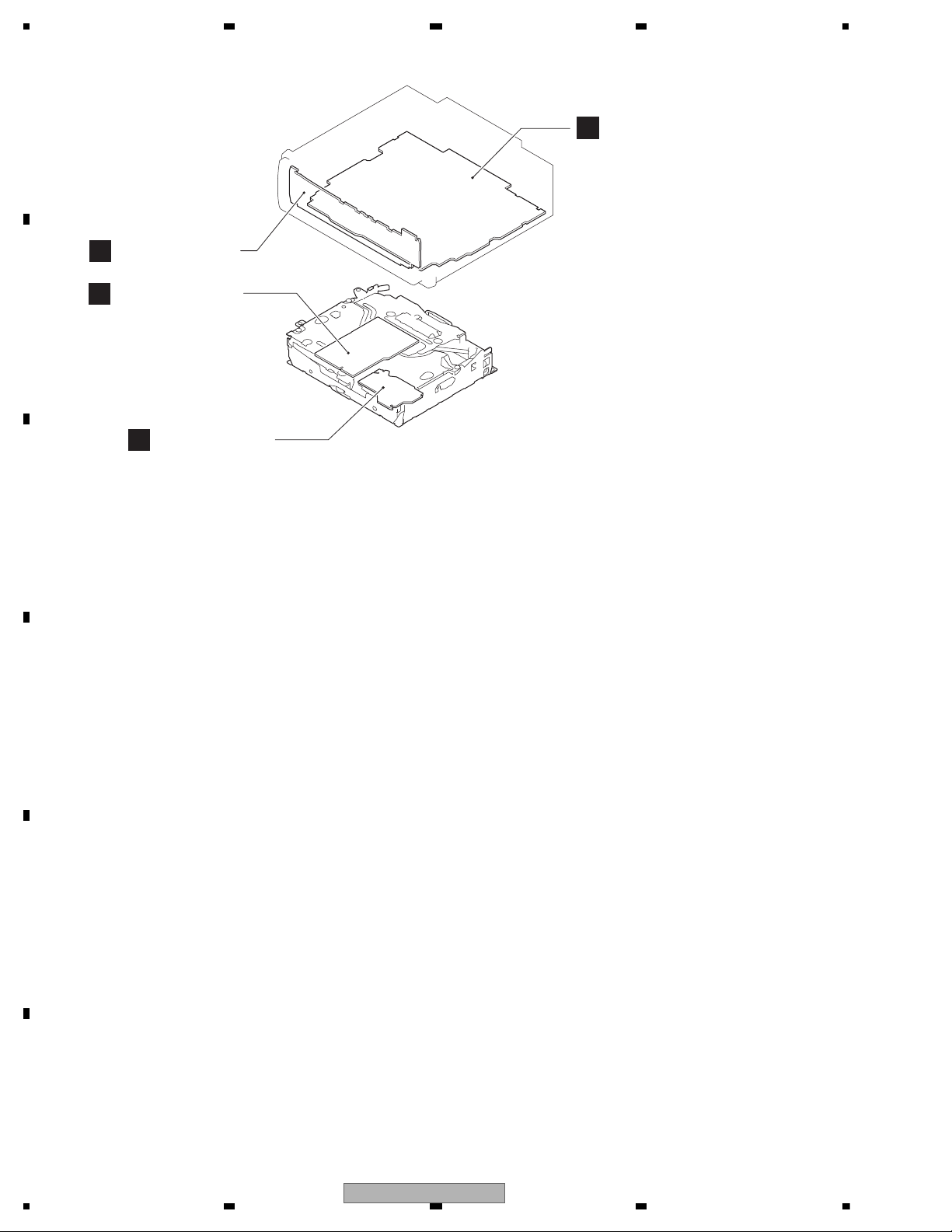
3.2 PCB LOCATIONS
A
B
Keyboard Unit
C
Tuner Amp Unit
DVD Core Unit
D
Connect PCB
A:DVH-3150UB/XN/RC
B:DVH-3150UB/XN/RD
C:DVH-3150UB/XN/RI
D:DVH-3150UB/XN/CN5
E:DVH-3150UB/XN/ID
Unit Number : CWN3740(A)
Unit Number : CWN3741(B)
Unit Number : CWN3742(C)
Unit Number : CWN3743(D)
Unit Number : CWN3748(E)
Unit Name : Tuner Amp Unit
Unit Number :
Unit Name : Keyboard Unit
Unit Number : YWX5007
Unit Name : DVD Core Unit
Unit Number :
Unit Name : Connect PCB
20
DVH-3150UB/XN/RC
5678
56
7
8
C
D
F
A
B
E
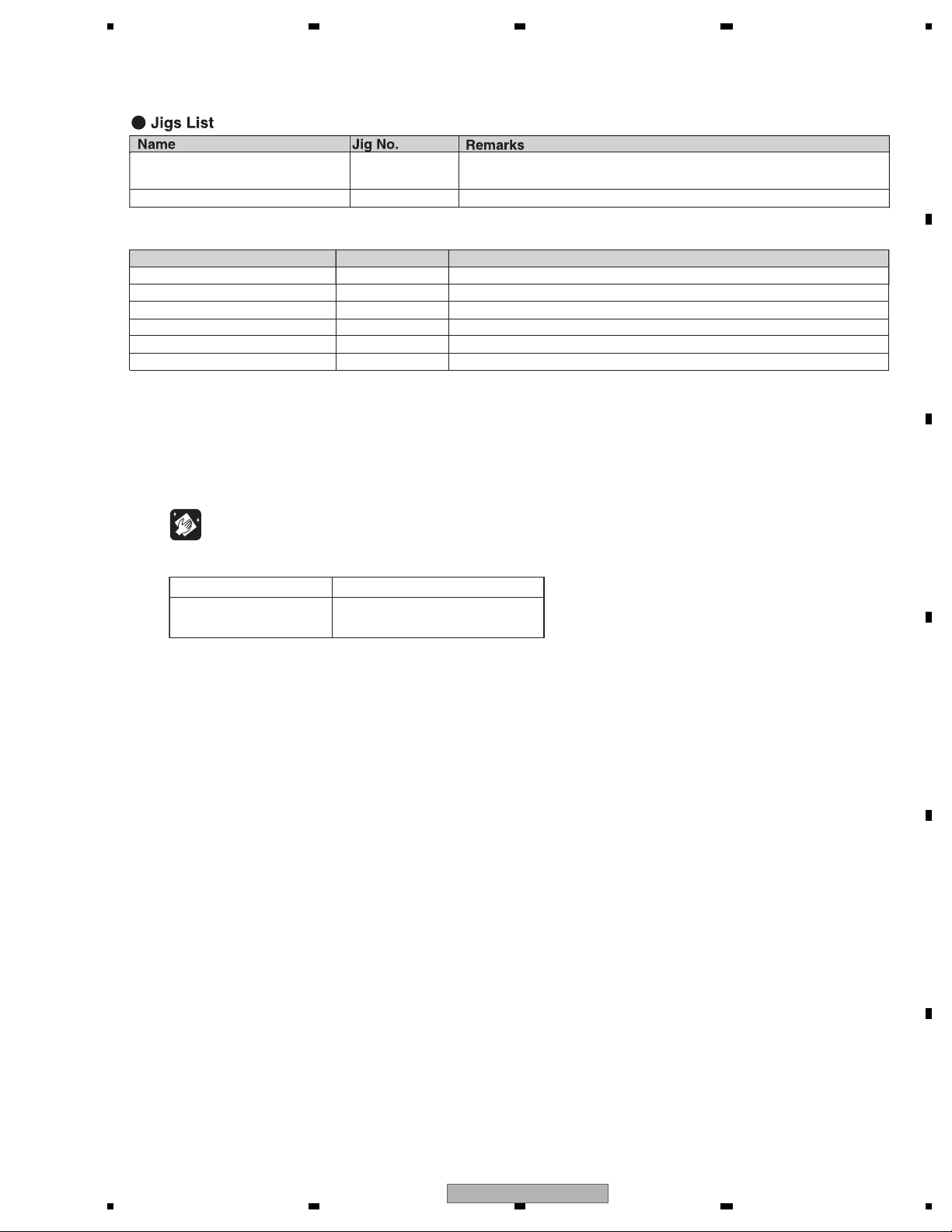
- Grease List
Name
Grease
Grease
Grease
Locking agents
Bond
Bond
Jig No.
GEM1024
GEM1038
GEM1045
1401M
GEM1033
1530
Remarks
DVD Mechanism Module
DVD Mechanism Module
DVD Mechanism Module
Skew adjustment (1401M:produced by THREE BOND)
Skew adjustment
Skew adjustment (1401M:produced by THREE BOND)
Disc TDV-582 Skew adjustment, Check points after servicing,
Inspection method of Pickup Unit
Disc TCD-782 Inspection method of Pickup Unit
Before shipping out the product, be sure to clean the following portions by using the prescribed cleaning tools:
Portions to be cleaned Cleaning tools
DVD pickup lenses Cleaning liquid : GEM1004
Cleaning paper : GED-008
3.3 JIGS LIST
3.4 CLEANING
DVH-3150UB/XN/RC
21
1234
1234
C
D
F
A
B
E
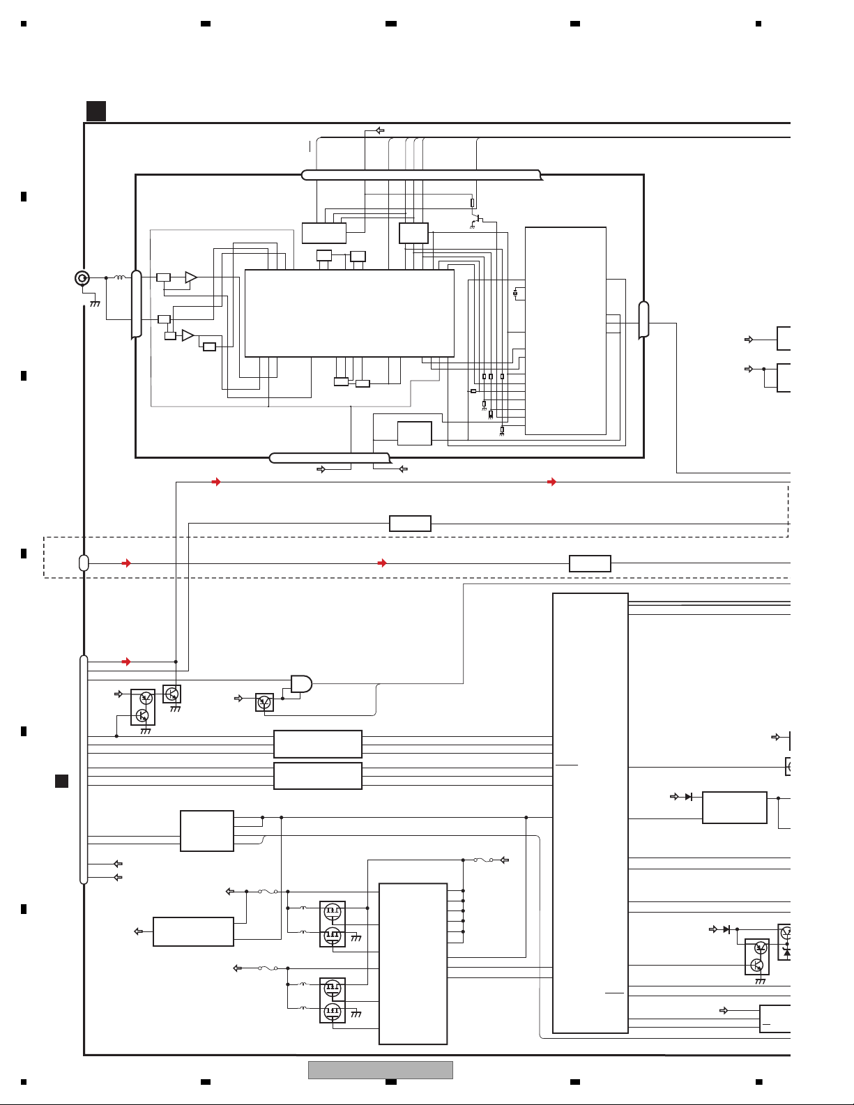
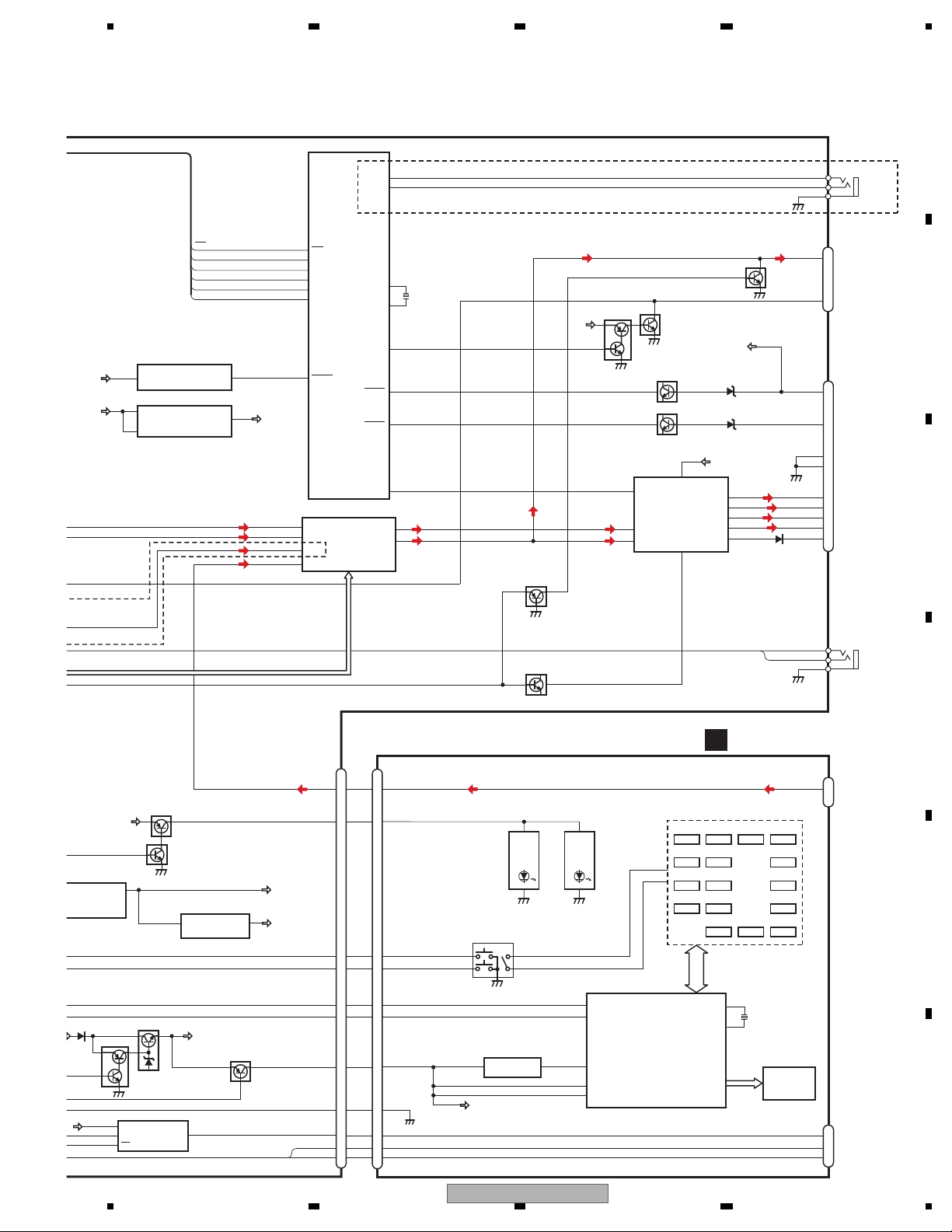
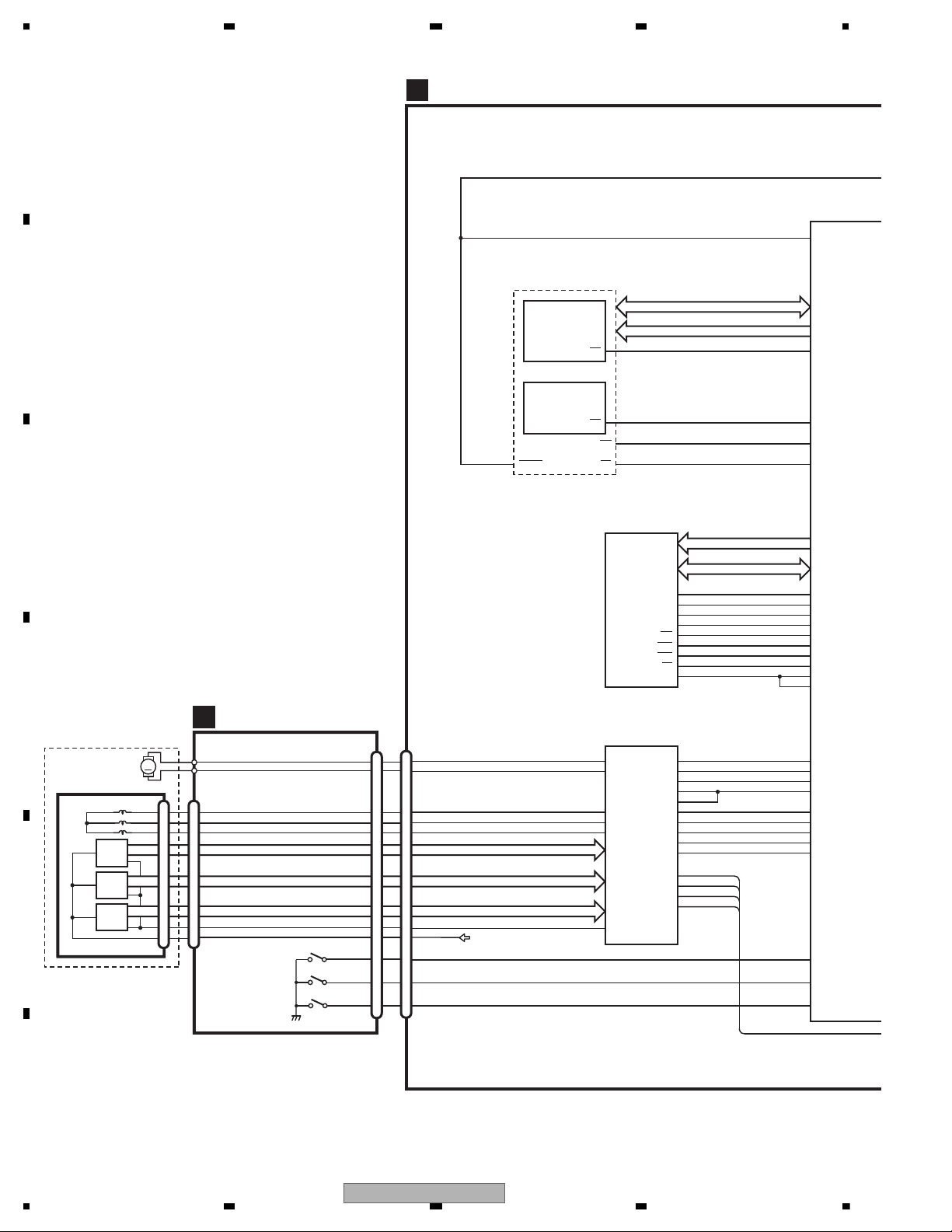
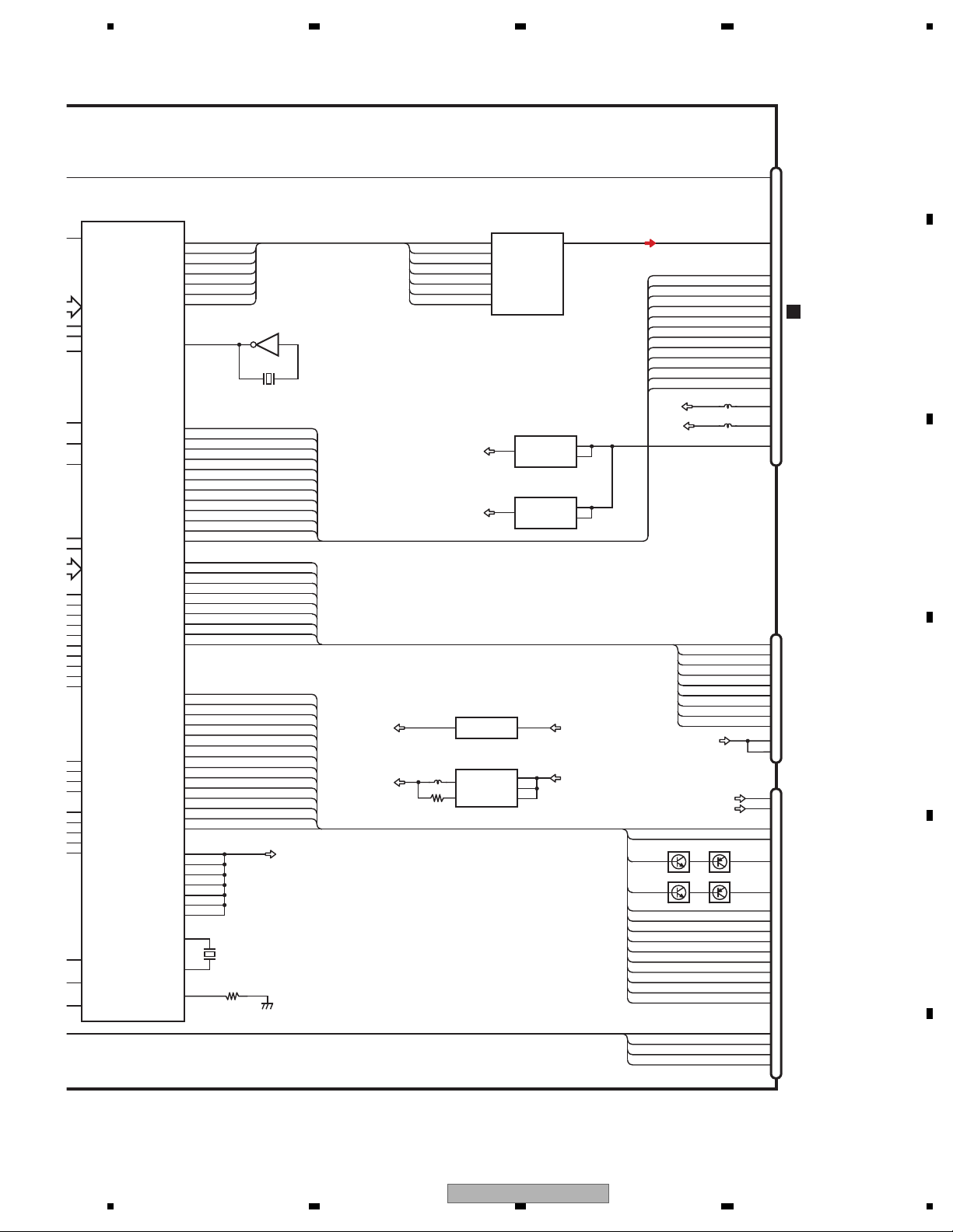
4. BLOCK DIAGRAM
AMUTE
48
MUTE
SYSTEM
CONTROLLER
JA471
1
2,3
CN101
TUNER AMP UNIT
3
1
A
25
17
1
|
3
TU33
VDD
ANTENNA
VCR IN
VCRL
JA282
(1/2)
4
23
22
7
CE2
SL
TUNPCK
CE1
TUNPDI
TUNPDO
VD5
VD8
IC601(2/2)
PEG525A
AMUTE
RXLS1
STANDBY
IRQPW
TXLS1
VDCONT5
IC111
TC74VHCT08AFTS1
3V
→
5V
VD8
VD5
8
1
12
4
MS5→SRX
STANBY
13
12
3
6
11
Q111
SYS+B
XRESET
45
ACCPW
19
DSENS
5
SWVDD
SYSPW
USBCTL
XRES
IC112
TC74VHC08FTS1
5V
→
3V
9
11
10
8
IRQPWR
D+
D-
S→MS5TX
11
3
2
3
5
12
9
1
1
13
12
11
SYS+B
43
59
46
24
SYNC
VDCONT8
34
42
40
41
33
Q112
Q321
BUP
VD5
VD5
Q105
Q1052
4A
3A
1A
1A
2A
4A
4Y
3Y
1Y
1Y
2Y
4Y
P1191
P1121
P1131
LSL
LSV
IECOUT
LOUT
19
COMPOSIT
IC311
TC7SET08FUS1
OPT3
OPT2(OPTOUT)
IC122
TC7MBL6126SFK
B2
B1
D-
D+
1OE
2OE
A1
A2
1
2
5
4
1
USB
IC1
R5523
VIN
EN
C
CN1901
VDD5
VD
VDD 5V
ILMPW
3
I
82
3
OC
4
USBFLG
85
VDD
VIN
ON/O
D/D CONVERTER
IC1103
BD9013KV
BUP
1
ROT0
ROT1
1
2
DPDT
KYDT
30
29
FMRF
ANT adj
RF adj
FM ANT
T51
CF52
RFGND
OSCGND
DGND
AUDIOGNDNCVCC
VDD_3.3
3.3V
2.5V
IC4
3.3V 2.5V
IC2
2.5V
NC
CE2
ROM_VDD
SL
DI
CK
CE1
DO
76 13 5 1098 11 14 1819 20 21
1
3
212 1522 16 4 17
IC1
3.3V
AM ANT
FMRF
ATT
LPF
OSC
IC3 EEPROM
5.0V
IC5
5V 3.3V
ATT
MIXER, IF AMP
DET, FM MPX
23
Lch
FM/AM TUNER UNIT
NC
NC
NC
NC
NC
→
→
BUP
2
VDD
8
VCCCL1
7
VCC
5
VCCCL2
10
CL1
3
CL2
27
EN2
34
SYNC
41
EXTVCC
26
EN1
OUT
IN
IC231
NJM4558MD
OUT1
IN+1
3
4
2
75ΩDRIVER +6dB AMP
IC181
TK15405BMI
IC1111
S-1200B33-M5
VD3
3
1
ON/OFF
VIN
VOUT
VD 3V
46
1
Q1191
OUTL2
OUTH2
48
SW2
15
12
Q1151
OUTL1
OUTH1
13
SW1
50
1
4
IC1021
NJM2388F84
2
BUP
VIN
CONTROL
VOUT
SYS+B
DVH-P3150UB/XN/RC, P3190UB/XN/ID Only
22
DVH-3150UB/XN/RC
5678
56
7
8
C
D
F
A
B
E
BSENS
ASENS
18
17
6
Front_L
7
Rear_L
5
3
21
23
FL+
FL-
RL+
RL-
IN1_L
1
IN2-_L
2
FLIN
12
RLIN
14
22
4
IC201
PML014A
AMP
IC271
PA2030A
Q751(2/2)
ELECTRONIC VOLUME/
SOURCE SELECTOR
STBY
MUTE
3
1
SWVDD
VST,VCK,VDT
TUNL
LSL
IC601(1/2)
PEG525A
SYSTEM
CONTROLLER
VMUTE
70
KEYAD
89
KEYD
90
25
B.REMOTE
10
12
11
9
4
CN821
SL
CE1
TUNPDO
TUNPDI
95
10
63
64
84
66
TUNPCK
65
CE1
TUNPDO
TUNPDI
TUNPCK
SL
BUP
6,20
JA282
(2/2)
RL-
RL+
FL-
FL+
POWER
CONNECTOR
RCA OUT
GND
BREM
CE2
CE2
1
ACC
5
1
B.U
VCC1/2,3/4
49
AMPPW
VDD3
Q1051
Q1052
Q1041
VDD
USB 5V
IC1101
R5523N001B
VIN
EN
VOUT
5
SWDVDD
VDD 5V
ILM+B
5
DPDT
KYDT
USB5V
D-
3
OC
4
OPT-OUT
JA321
RESET
VDD
VDD 3V
IC1001
S-1200B33-M5
VIN
ON/OFF
VOUT
RESET
IC661
BD4835G
MUTE
BSENS
ASENS
6
17
16
D+
1
14
18
7
12
AUXL
ILM+B
ROT0
4
ROT1
19
3
DSENS
20
OPT3
OPT2(OPTOUT)
3
2
1
WIRED
REMOTE
JA331
KEYD
KEYAD
3
2
1
3
Q282
RL
Q751(1/2)
2
VGND
8
BUP
Q261(1/2)
MUTE
Q261(2/2)
XOUT
XIN
11
X601
15.000MHz
13
BUP
Q1061
Q1062
2
VDD
IN3_L
3
AVSIVCRL
IN4+_L
4
AUXL
IC1802
GP1UXC14RK
REMOTE CONTROL
SENSOR
FRONT
AUX
AUXL
SW5V
ILM+B
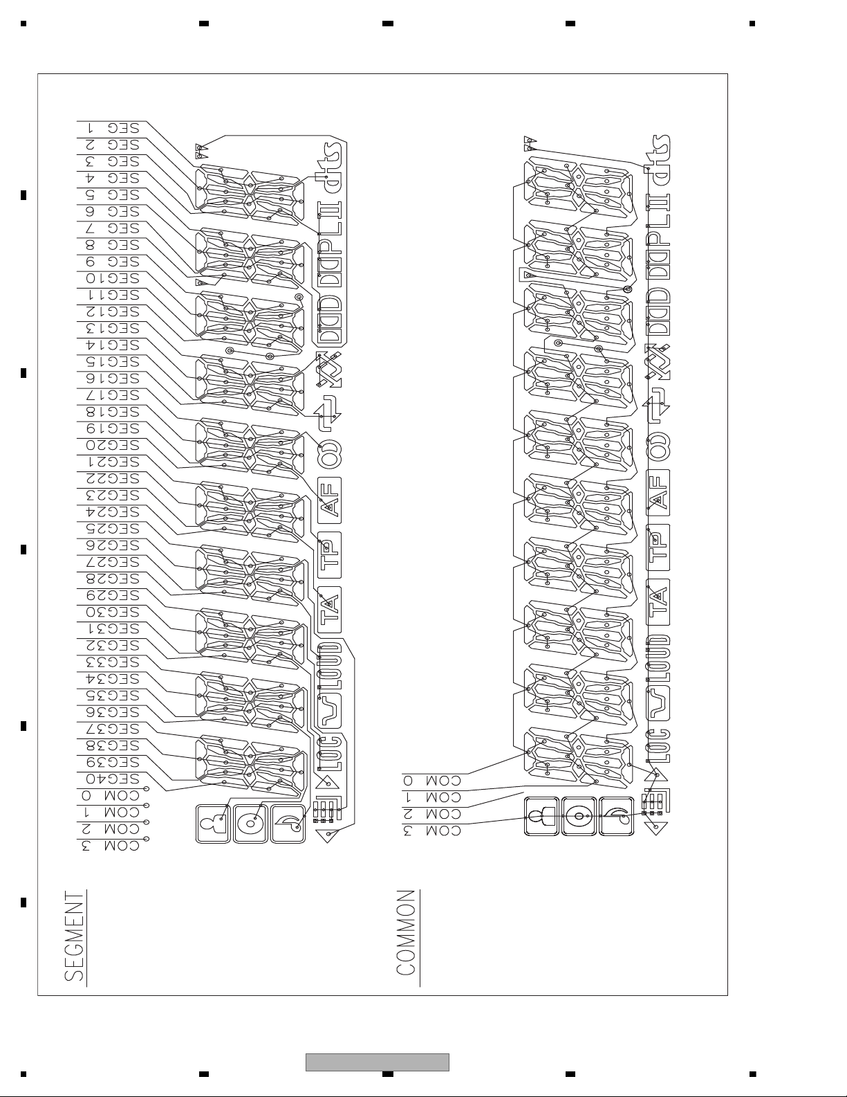
LCD DRIVER/
KEY CONTROLLER
IC1801
PD6497A
CN1801
JA1802
CN701
CN1803
KYDT
SW5V
DPDT
AUXL
DSENS
USB5V
DP
DM
20
18
17
10
3
56
SI/P43
SO/P44
V3
VDD
INT1/PWC/P42
KEY MATRIX
LCD
V1801
X0
X1
22
1
X1801
5MHz
23
ROTARY COMMANDER
S1833
1
2
4
5
ROT1
ROT0
KDT2
KST1
LCD BK
D1823
BLUE
ILLUMI
S1831
S1832
LEFT
S1802
SRC
S1815
6
S1829
S1830
UP
S1823
LIST
S1813
5
S1827
S1828
RIGHT
S18091S1807
2
S1803
S1834
EJECT
S1819
REGION
S1825
S1826
DOWN
S1801
BAND/ESC
S1811
4
S1805
3
S1817
DISP
KEYBOARD UNIT
B
7
4
17
19
3
20
6
18
16
12
14
3
USB
USB5V
DP
DM
1
3
2
D1840
-
D1851
D1855
-
D1857
D1859
KDT0-3,
KST0-4
1
VOUT
Q291
BUP
Q292
IC1021
NJM2388F84
IC1011
NJM2885DL1-33
2
SYS+B
31
TU3.3
NTROL
VOUT
TUNER 3V
SYS+B
DVH-P3150UB/XN/CN5 Only
RL
Vo
DVH-3150UB/XN/RC
23
1234
1234
C
D
F
A
B
E
MA0-11
MDQ0-15
D0-15
VIDEO+AUD
IC1501
MN2DS0018M
S
S
USB_
TRC
TRC
TRC
T
S
E
F+
E+
D
COM
ST
CMD
ST
IR
E
TRC
NRES
A0-19
HWP(HW+),HWM(HW-)
HVP(HV+),HVM(HV-)
HUP(HU+),HUM(HU-)
HWP(HW+),HWM(HW-)
HVP(HV+),HVM(HV-)
HUP(HU+),HUM(HU-)
XRDNRES 28 214
NEXOE
NEXWE
70
NRES
I
I2
CP
I2
59
XCSSR
213
31
NEXCE
26
12
CE
OE
RESET
SDRAM
IC1480
K4S641632N-LC75
19
38
CS
CLK
XWE16 181
NWE
XCAS
DQM0
DQM1
17 188
NCAS
XRAS18 189
NRAS
XCSM 190
NCSM
20 193
BA0
21 197
BA1
BA0
BA1
15 179
DQM0
39
8
9
12
5
6
7
3
4
1
2
32
31
27
26
28
14
180
DQM1
LDQM
UDQM
MCK
VHALF
TD
FD
CRGDRV
MD
CONT1
CONT2
FOP
FOM
TOP
TOM
183
MCK
185
MCKI
V
CAS
RAS
WE
MOTOR DRIVER
IC1201
BD8231EFV
CTL1
CTL2
FG
FCO+
FCOTKO-
TKO+
FCIN
SLIN
VC
TKIN
LDIN
SPIN
W
HB
SL/LDOSL/LDO+
V
U
SLOPOUT
CN1201
CN101
CN701
CRG/LE+
COIL_U
17
18
16
6
3
4
5
9
8
7
HALL_BIASHALL_BIAS+
COIL_V
COIL_W
67
127
126
66
71
64
63
FG
CONT2
CONT1
12EJ
08EJ
HOME
62
MD
LDIN
CRGDRV
FD
TD
34
36
35
33
55
49
65
CRG/LE- 110
VHALF
FLASH 16M
IC1401
CWW1753
XCFS2
XCFS1
26
11 XWR1
CE
WE
IC1402
CWW1754
DVD CORE UNIT
C
VCC5
BR
GY
CRG-
CRG+
V COIL V
U COIL U
W COIL W
V
U
W
H- HALL BIASH+
H-
H+ HALL BIAS+
HOME
8SNS
DSCSNS
HOME
8cm
12cm(DSCSNS)
CONNECT PCB
SPINDLE MOTOR
LS1 MECHA UNIT
D
2
1
3
13
16
15
14
10
11
12
1
2
3
4
10
1
2
3
4
10
M
LOADING/CARRIAGE
MOTOR
HOME
S101
8cm
S102
12cm
S103
H3
H2
H1
24
DVH-3150UB/XN/RC
5678
56
7
8
C
D
F
A
B
E
VIDEO+AUDIO
IC1501
MN2DS0018MAUB
AVCC5
VOUTL
7
BCK
LRCK
DATA
MD
1
3
2
13
AUDIO 2CH ANALOG OUT
IC1801
PCM1753DBQ
LOUT
ML
MC
SCK
SRCK
LRCK
ADOUT
SDODAC
LTDAC
SCKDAC
DACCK
USB_CLOCK
15
14
16
149
150
151
57
56
58
148
50 2
SRCK
ADOUT
SDODAC
LRCK
LTDAC
SCKDAC
DACCK
TRCST
TRCDATA3
TRCDATA2
TRCDATA1
TRCDATA0
TRCCLK
EXTRG0
1
2
3
4
9
7
12
8
13
5
6
Q1104Q1102
VREF
VCC5
CN1101
CN1951
78LD
F+H_G+H
E+G_E+F
F+H/G+H
E+G/E+F
LPCO2
8
2
3
4
14
15
12
18
17
13
20
22
7
5
11
Q1103Q1101
65LD
VCC
Vref
LPCO1
TRCDATA2
79
TRCDATA3
TRCDATA0
TRCST
80
77
81
TRCCLK
76
SDATA
SCLOCK
SDATA
73
SCLOCK
72
EXTRG0
F+H_G+H
E+G_E+F
VIN4RF
VIN2RF
VIN1RF
VIN3RF
VIN8
DVDMPD
TEMP
RFINP
CDMPD
LPCO2
LPCO1
74
112
111
99
98
97
100
116
105
A
C
D
B
FE1
FE2
RF
122
96
103
106
104
5
1
3
VIN
VOUT
ON/OFF
AVCC5 REG.
IC1003
S-1200B50-M5
VCC5
VD8
5
4
3
VIN
VOUT
ON/OFF
VCC5 REG.
IC1002
S-1133850-U5
A
10
B
C
D
FE1
FE2
78MDCDMPD
65MDDVDMPD
TEMP
RF
ROUT
LOUT
COMPOSITE
152
146
144
138
STANDBY
191
CMDCOMN
53
STSCOMN
54
IRQPWR
48
EXTRG1
75
D+
4
D-
AMUTE
24
25
23
26
F-
F+
FOM
FOP
TOP
TOM
T+
T-
TRCDATA1
78
IFCOUT
D+
D-
SCL
SDA
RESET
COMPOSIT
STANBY
SLVSTS
HSTCMD
STSCOMN
CMDCOMN
COMPOSITE
STANDBY
ISC_SCL
I2C_SDA
CP_Reset
IRQPWR
AMUTE
VD8
XRESETNRES
OSCO
OSCI
X1501
156
155
X1950
ANALOG LOUT
CN1901
9
3
17
25
27
28
29
23
11
10
13
8
7
12
1
.
2
22
19
VREF
NEXOE
NEXWE
70
NRES
IECOUT
I2C_SDA
CP_Reset
47
46
61
I2C_SCL
59
XCSSR
31
NEXCE
181
NWE
188
NCAS
189
NRAS
190
NCSM
193
BA0
197
BA1
179
DQM0
180
DQM1
183
MCK
185
121
MCKI
VDSENS
IC1951
TC7SZU04FU
67
66
71
64
63
FG
CONT2
CONT1
12EJ
08EJ
HOME
62
MD
LDIN
CRGDRV
FD
TD
120
VIN1
109
VREFH
119
VIN2
118
VIN4
117
VIN3
114
VIN6
113
VIN5
55
49
65
VHALF
VIN7
115
13
VCC33 VDD5
VCC33
3.3V REG.
IC1004
NJM2885DL1-33
INOUT
2
8
VDD5
VCC12
1.2V REG.
IC1005
R1232D121B
VIN
VDD
CE
LX
5
VOUT
VDD5
VD5
PU (DP10)
DEBUG
CN101
A
3
4
DVH-3150UB/XN/RC
25
1234
1234
C
D
F
A
B
E
- CAW1964
26
DVH-3150UB/XN/RC
5678
56
7
8
C
D
F
A
B
E
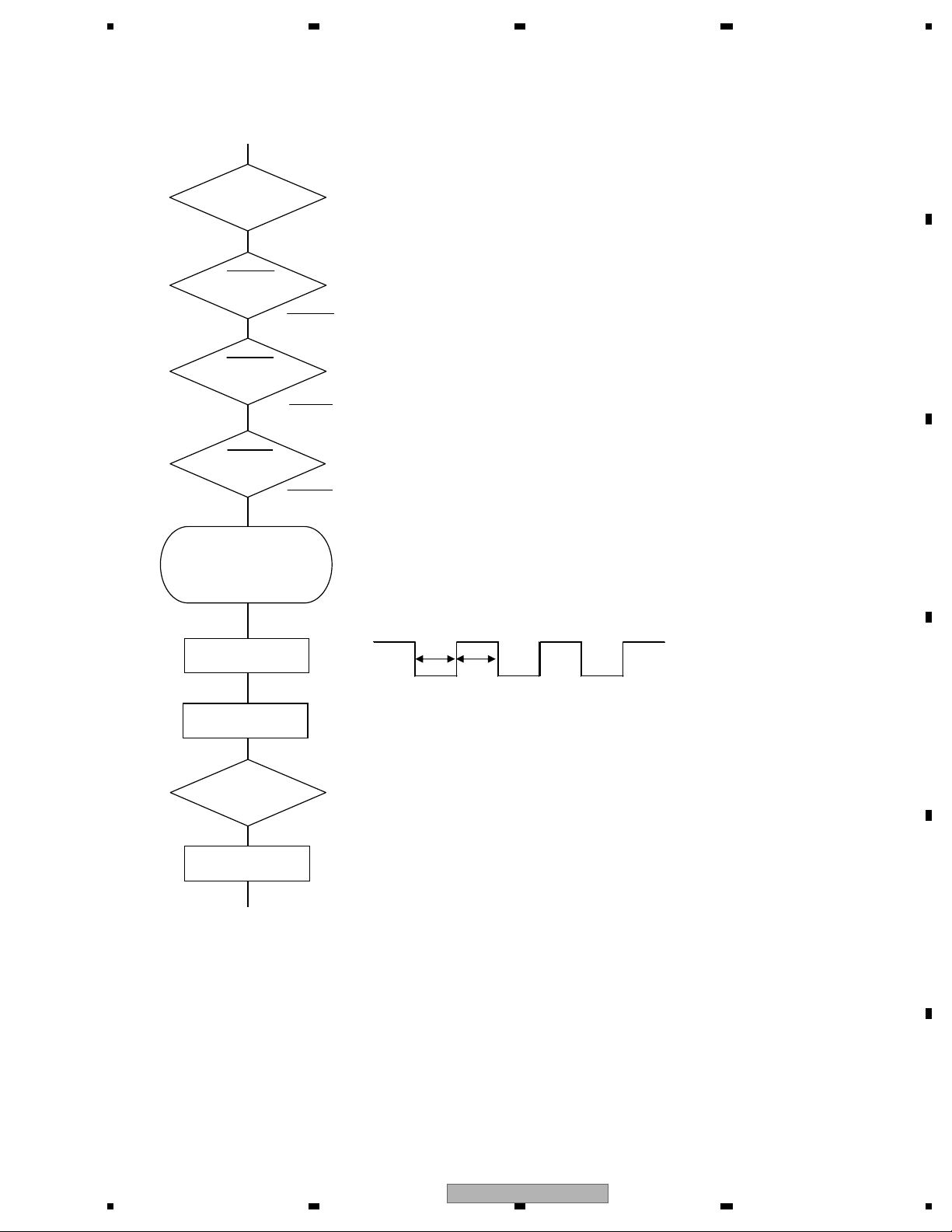
VDD = 5 V
Pin 14, 60
BSENS
Pin 17
ASENS
Pin 18
DSENS
Pin 19
BSENS = L
DSENS = L
Starts
communication
with Grille
microcomputer.
SWVDD <- H
Pin 5
Source keys
operative
Source ON
SYSPW <- H
Pin 50
Completes power-on operation.
(After that, proceed to each source operation)
500 ms
500 ms
In case of the above signal, the communication
with Grille microcomputer may fail.
If the time interval is not 500 msec, the oscillator
may be defective.
Power ON
ASENS = L
5. DIAGNOSIS
5.1 OPERATIONAL FLOWCHART
DVH-3150UB/XN/RC
27
1234
1234
C
D
F
A
B
E
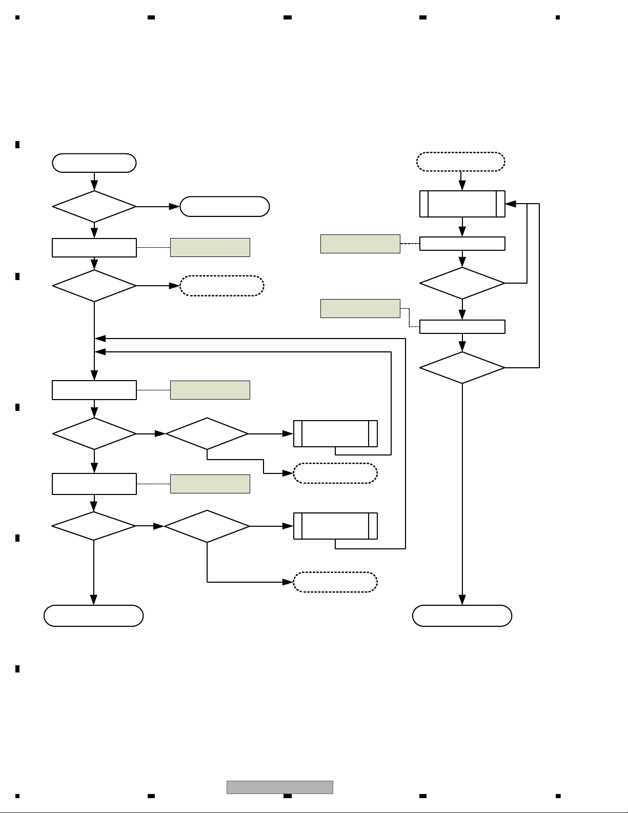
5.2 INSPECTION METHOD OF PICKUP UNIT
Disc to be used
CD-DA: TCD-782
DVD-Video: TDV-582
Execution method
START
Is it OK?
Is it OK?
Ckeck parts
other than PICK UP
PICK UP
cleaned?
Perform lens
cleaning
SKEW ADJ.
Is it OK?
LD current check
RF level check
RF level check
Yes
Error rate check
Finished
LD turned on? Check parts
No
Is it OK?
PICK UP
cleaned?
Perform lens
cleaning
Error rate check
Is it OK?
Replace the PICK UP
Replace the PICK UP
Replace the PICK UP
Replace the PICK UP
Check point:
AS MAX check
Check point:
LD current check
Check point:
Error rate check
Yes
No
Yes
No
Yes
No
Yes
No
Yes
No
Yes
No
Yes
No
Check point:
AS MAX check
Check point:
Error rate check
28
DVH-3150UB/XN/RC
5678
56
7
8
C
D
F
A
B
E
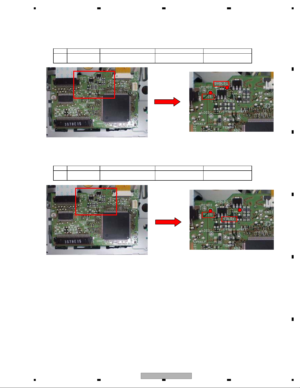
LD current check
Check
Status: [Foucs closed] of TEST MODE
Notes: Please pay attention to the laser diode damage by static electricity.
Threshold
2 TCD-782 CDLD1-VCC5_3 60 - 360 (mV) 10 - 60 (mA)
NO. Disc Check Point
Check Point
DVDLD1-VCC5_3
NO.1Disc
GGV1025
Remarks: LD current
10 - 65 (mA)
Threshold
60 - 390 (mV)
Expansion
Expansion
Remarks: LD current
DVH-3150UB/XN/RC
29
1234
1234
C
D
F
A
B
E
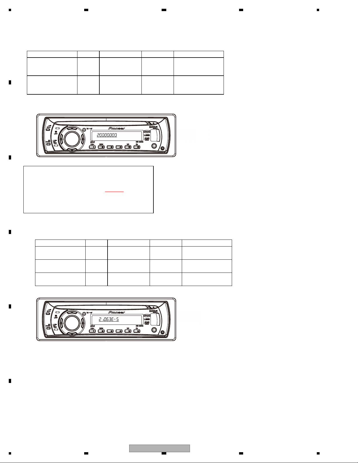
ASMAX check
ASMAX value shows the value of RF level.
Status: [Foucs closed] of TEST MODE
No. Disc Check Point Threshold Remarks:
8 digits value of
ASMAX
more than
on display 0000 0B00
8 digits value of
ASMAX
more than
on display 0000 0C00
Error rate check
Status: [Tracking Closed] of TEST MODE
No. Disc Check Point Threshold Remarks:
less than
1.000E-03
less than
1.000E-03
less than
2.500E-03
3 TCD-782 ID: HOME Position
2
GGV1025
ID: 200000
1
GGV1025
ID: 40000
1
GGV1025
Only four last digits are
displayed according to
the product.
2 TCD-782
Only four last digits is
displayed according to
the product.
In this case, the value is displayed for a split second.
When you tried to perform [FOCS CLOSE],
the display will charge automatically in the following order.
[1FFF0000]->[FEMAX]->[FE MIN]->[AS MAX
]->
[ENV MAX]->[FE normal]->[Spindle gain]->
[TEMAX]->[TEMIN] ->[20000000]
Watch carefully the value of ASMAX.
30
DVH-3150UB/XN/RC
Loading...