


DVH-P4100UB

Installation Manual
Manual de instalación
Installationsanleitung
Manuel d’installation
Manuale d’installazione
Installatiehandleiding
DVD RDS RECEIVER
RADIO DVD
DVD-RDS-EMPFÄNGER
AUTORADIO DVD RDS
SINTO LETTORE DVD CON RDS
DVD RDS-ONTVANGER
DVH-P4100UB
English
Español
Deutsch
Français
Italiano
Nederlands
1
Connecting the Units ................................ 1
Power cable connection ....................................3
Connecting to separately sold power amp ........ 5
When connecting with a multi-channel
processor .................................................... 7
Connecting and installing the optical cable
connection box .......................................... 8
When using a display connected video
outputs ........................................................ 9
When connecting the external video
component ................................................ 10
Installation ................................................ 11
DIN Front/Rear-mount ....................................11
DIN Front-mount ............................................ 11
DIN Rear-mount .............................................. 12
Connecting the Units
Contents
WARNING
•To avoid the risk of accident and the potential violation of applicable laws, the front DVD or TV
(sold separately) feature should never be used
while the vehicle is being driven. Also, Rear
Displays should not be in a location where it is a
visible distraction to the driver.
• In some countries or states the viewing of images
on a display inside a vehicle even by persons other
than the driver may be illegal. Where such regulations apply, they must be obeyed and this unit’s
DVD features should not be used.
CAUTION
• PIONEER does not recommend that you install or
service your display yourself. Installing or servicing the product may expose you to risk of electric
shock or other hazards. Refer all installation and
servicing of your display to authorized Pioneer
service personnel.
• Secure all wiring with cable clamps or adhesive
tape. Do not allow any bare wiring to remain
exposed.
•Do not drill a hole into the engine compartment to
connect the yellow lead of the unit to the vehicle
battery. Engine vibration may eventually cause the
insulation to fail at the point where the wire passes
from the passenger compartment into the engine
compartment. Take extra care in securing the wire
at this point.
• It is extremely dangerous to allow the display lead
to become wound around the steering column or
gearshift. Be sure to install the display in such a
way that it will not obstruct driving.
•Make sure that wires will not interfere with moving parts of the vehicle, such as the gearshift,
parking brake or seat sliding mechanism.
• Do not shorten any leads. If you do, the protection
circuit may fail to work properly.

English Español Deutsch
Français Italiano Nederlands
Note:
• This unit cannot be installed in a vehicle that
does not have an ACC (accessory) position on
the ignition switch.
•Use this unit in other than the following conditions could result in fire or malfunction.
—Vehicles with a 12-volt battery and negative
grounding.
— Speakers with 50 W (output value) and 4 ohm
to 8 ohm (impedance value).
• To prevent short-circuit, overheating or malfunction, be sure to follow the directions below.
—Disconnect the negative terminal of the bat-
tery before installation.
— Secure the wiring with cable clamps or adhe-
sive tape. To protect the wiring, wrap adhesive tape around them where they lie against
metal parts.
— Place all cables away from moving parts, such
as gear shift and seat rails.
— Place all cables away from hot places, such as
near the heater outlet.
—Do not pass the yellow cable through a hole
into the engine compartment to connect to a
battery.
—Cover any disconnected cable connectors with
insulating tape.
—Do not remove RCA caps if RCA cables are
not used.
—Do not shorten any cables.
—Never cut the insulation of the power cable of
this unit in order to share the power to other
equipment. Current capacity of the cable is
limited.
—Use a fuse of the rating prescribed.
— Never wire the speaker negative cable directly
to ground.
—Never band together multiple speaker’s nega-
tive cables.
•Control signal is output through blue/white cable
when this unit is powered on. Connect it to an
external power amp’s system remote control or
the vehicle’s auto-antenna relay control terminal
(max. 300 mA, 12 V DC). If the vehicle is
equipped with a glass antenna, connect it to the
antenna booster power supply terminal.
•Never connect blue/white cable to external power
amp’s power terminal. Also, never connect it to
the power terminal of the auto antenna.
Otherwise, battery drain or malfunction may
result.
• IP-BUS connectors are color-coded. Be sure to
connect connectors of the same color.
•Black cable is ground. This cable and other product’s ground cable (especially, high-current products such as power amp) must be wired separately. Otherwise, fire or malfunction may result if
they are accidentally detached.
No ACC positionACC position
2
C
C
A
O
F
N
F
O
S
T
A
R
T
O
F
N
F
O
S
T
A
R
T
3
Connecting the Units
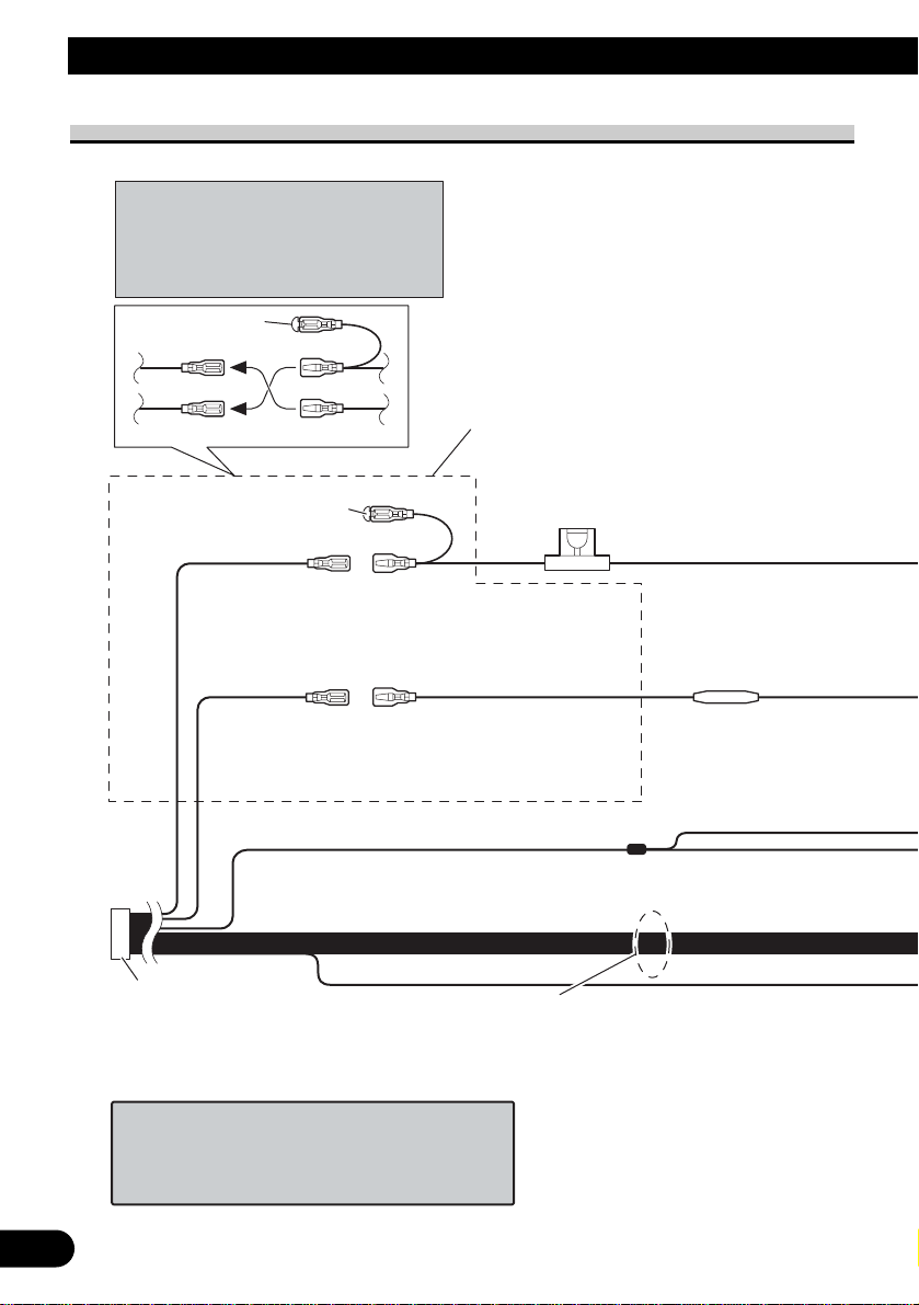
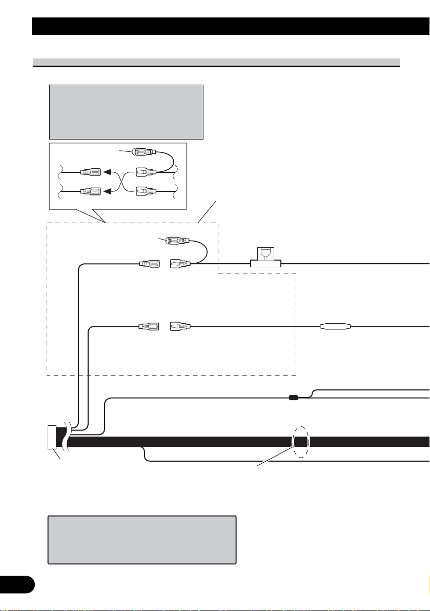
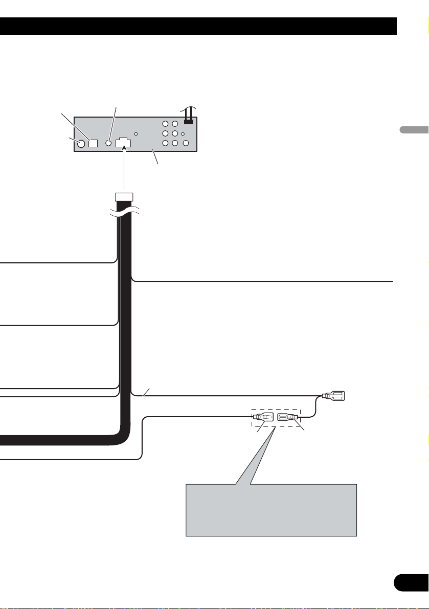
Power cable connection
1*
2*
4*
3*
5*
Note:
Depending on the kind of vehicle, the
function of 3* and 5* may be different. In
this case, be sure to connect 2* to 5* and 4*
to 3*.
Connect leads of the same
color to each other.
Cap (1*)
Do not remove cap if
this terminal is not in
use.
Yellow (3*)
Back-up (or
accessory)
Red (5*)
Accessory
(or back-up)
Yellow (2*)
Connect to the constant
12 V supply terminal.
Red (4*)
Connect to terminal controlled
by ignition switch (12 V DC).
ISO connector
Note:
In some vehicles, the ISO connector
may be divided into two. In this case,
be sure to connect to both connectors.
Speaker leads
White: Front left +
White/black: Front left ≠
Gray: Front right +
Gray/black: Front right ≠
Green: Rear left +
Green/black: Rear left ≠
Violet: Rear right +
Violet/black: Rear right ≠
Black (chassis ground)
Connect to a clean, paint-free metal location.
Fuse (10 A)
Fuse resistor
When you connect the separately sold multi-channel
processor (DEQ-P6600) to this unit, do not connect
anything to the speaker leads and system remote
control (blue/white).
English Español Deutsch
Français Italiano Nederlands
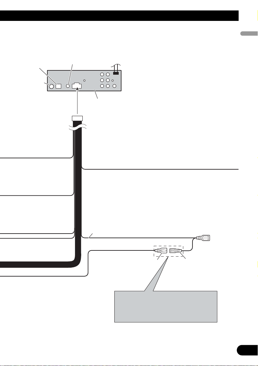
4
Blue/white
Connect to system control terminal of the
power amp (max. 300 mA 12 V DC).
Blue/white (7*)
Connect to auto-antenna
relay control terminal
(max. 300 mA 12 V DC).
The pin position of the ISO connector will differ
depends on the type of vehicle. Connect 6* and
7* when Pin 5 is an antenna control type. In
another type of vehicle, never connect 6* and 7*.
Yellow/black
If you use an equipment with Mute function, wire
this lead to the Audio Mute lead on that equipment.
If not, keep the Audio Mute lead free of any
connections.
This product
Wired remote input
Hard-wired remote control
adaptor can be connected
(sold separately).
IP-BUS input
(Blue)
Antenna jack
Blue/white (6*)
5
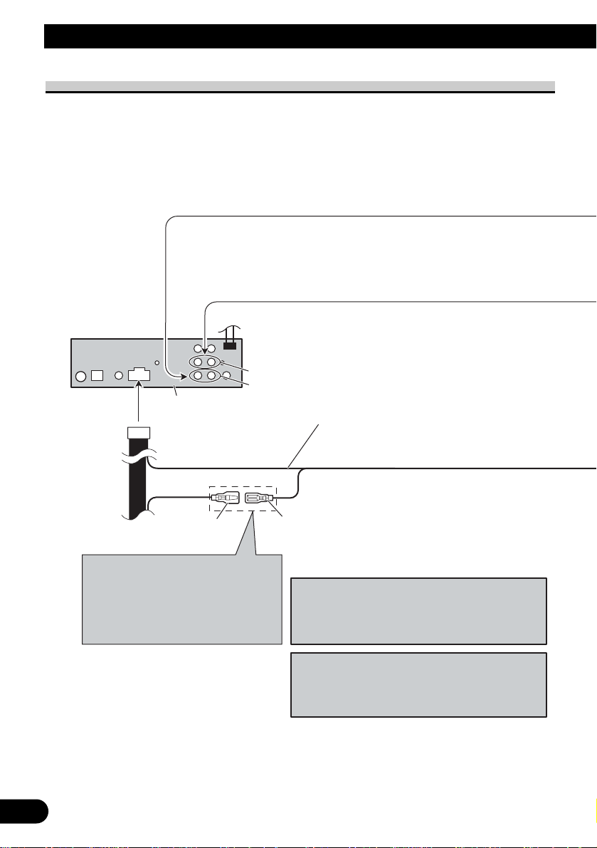
Connecting the Units
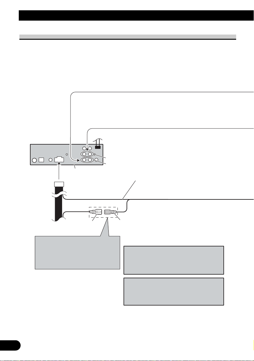
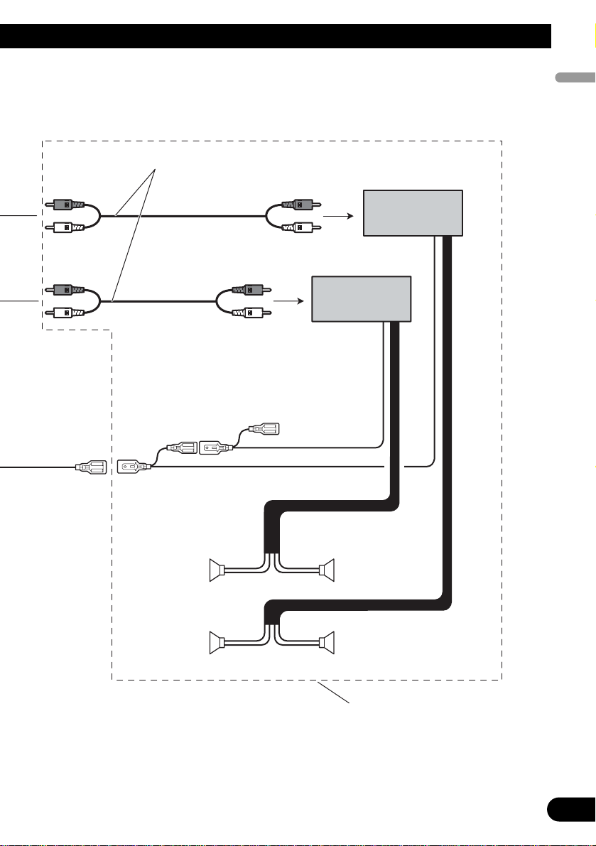
Connecting to separately sold power amp
Blue/white
Connect to system control terminal of the
power amp (max. 300 mA 12 V DC).
Blue/white (7*)
Connect to auto-antenna relay control
terminal (max. 300 mA 12 V DC).
The pin position of the ISO connector will
differ depends on the type of vehicle.
Connect 6* and 7* when Pin 5 is an
antenna control type. In another type of
vehicle, never connect 6* and 7*.
Blue/white (6*)
Rear output
Front output
When you connect separately sold multi-channel
processor (e.g. DEQ-P6600) to this unit, do not
connect anything to the speaker leads and system
remote control (blue/white).
Note:
When you connect multi-channel processor to
this unit, separately sold power amp must be
connected to multi-channel processor.
This product
English Español Deutsch
Français Italiano Nederlands
6
Connect with RCA cables
(sold separately)
Perform these connections when
using the optional amplifier.
Power amp (sold
separately)
Power amp (sold
separately)
System remote control
Front speaker
Front speaker
+
≠
+
≠
+
≠
+
≠
Left Right
Rear speakerRear speaker

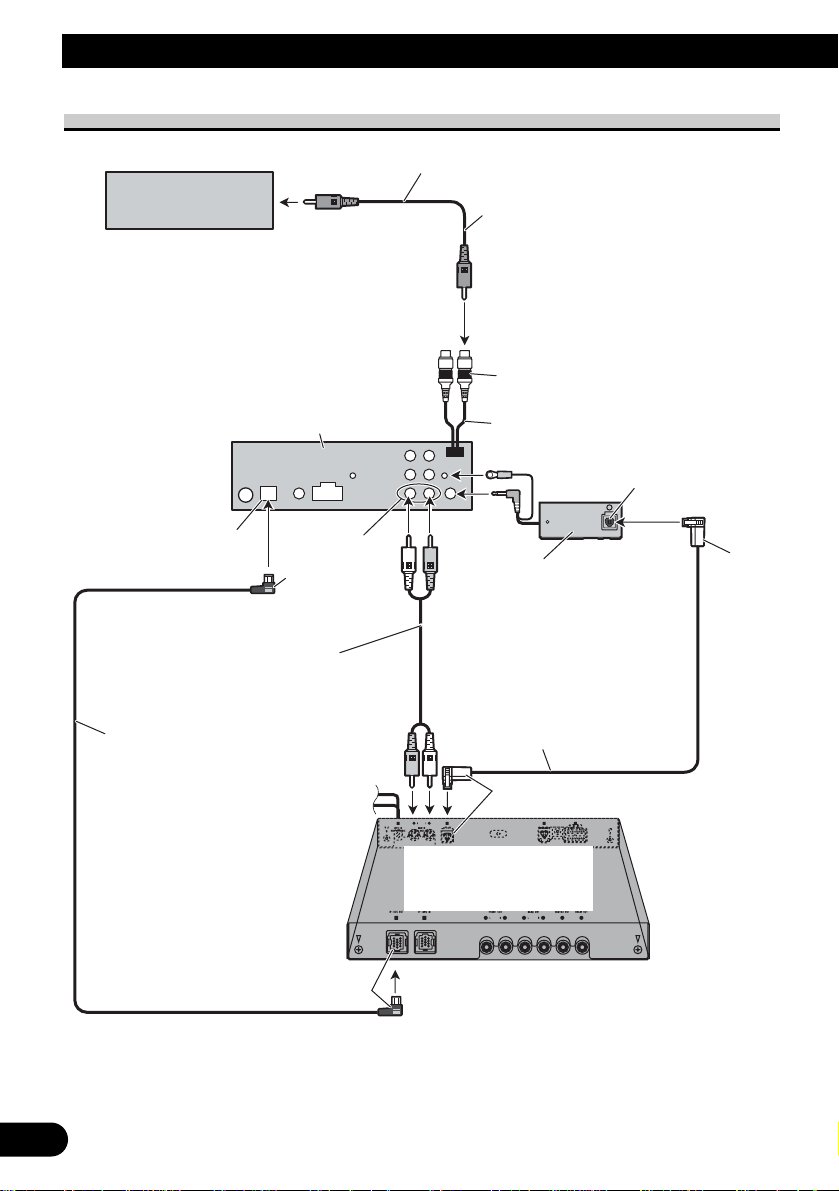
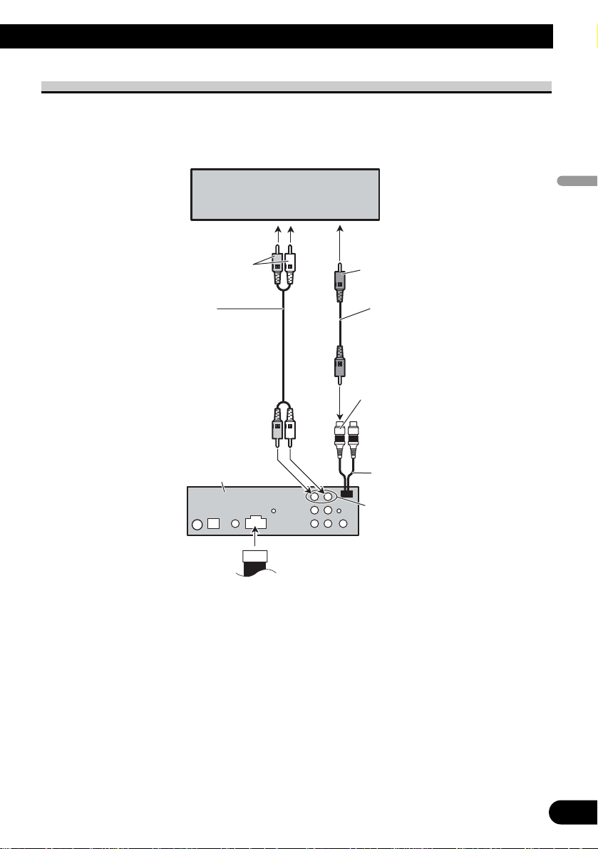
When connecting with a multi-channel processor
7
Connecting the Units
k
1.5 m
AV system display
To video input
This product
RCA cable
(supplied)
Video output
(VIDEO OUTPUT)
15 cm
Black
Blue
Blue
RCA cable
(supplied with multichannel processor)
IP-BUS cable
(supplied with multi-channel
processor)
DEQ output
Black
Optical cable connection
box (supplied with multichannel processor)
Optical cable
(supplied with multichannel processor)
Blue
Multi-channel processor
(DEQ-P6600)
(sold separately)
Blac
8
English Español Deutsch
Français Italiano Nederlands
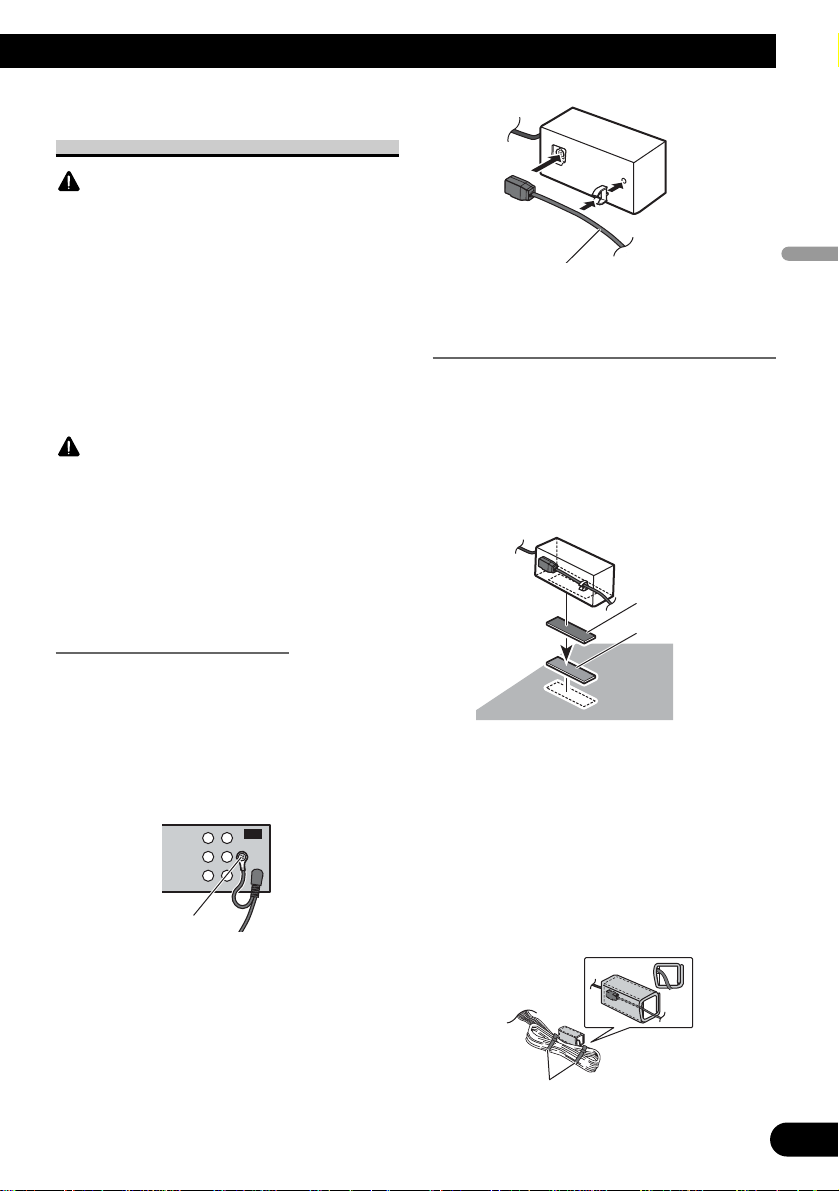
Connecting and installing the
optical cable connection box
WARNING
•Avoid installing this unit in locations where the
operation of safety devices such as airbags is prevented by this unit. Otherwise, there is a danger of
a fatal accident.
•Avoid installing this unit in locations where the
operation of the brake may be prevented.
Otherwise, it may result in a traffic accident.
•Fix this unit securely with the hook and loop fastener or lock tie. If this unit is loose, it disturbs
driving stability, which may result in a traffic accident.
CAUTION
• Install this unit using only the parts supplied with
this unit. If other parts are used, this unit may be
damaged or could dismount itself, which leads to
an accident or other problems.
•Do not install this unit near the doors where rainwater is likely to be spilled on the unit. Incursion
of water into the unit may cause smoke or fire.
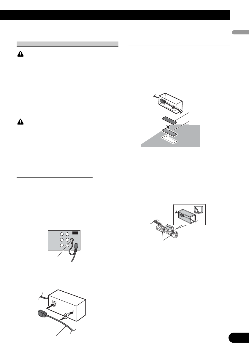
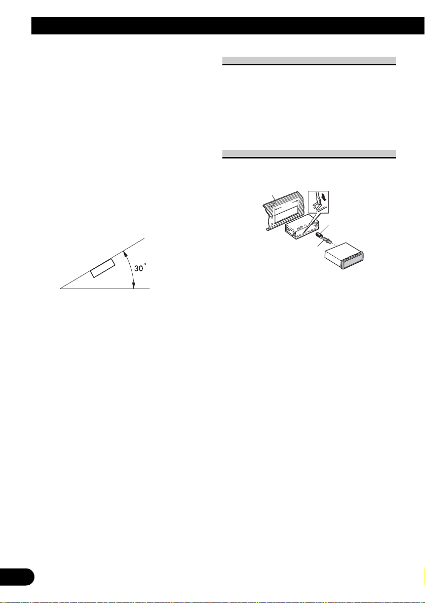
Connecting the optical cable
1. Connect the optical cable and
ground lead to the main unit.
Connect the optical cable so that it
does not protrude from the unit, as
shown in the illustration. Fasten the
ground lead to the protrusion on the
back of the unit.
2.
Connect the optical cable to the
optical cable connection box.
Installing the optical cable
connection box
• When
installing the optical cable
connection box with the hook and
loop fastener.
Install the optical cable connection box
using the hook and loop fastener in the
ample space of the console box.
•When installing the optical cable
connection box with the lock tie.
Wrap the optical cable and connection
box with the protection tape and fasten
with the power code using the lock tie.
Screw
Optical cable
Hook fastener
Loop fastener
Wrap with the protection tape
Fasten with the lock tie
9
Connecting the Units
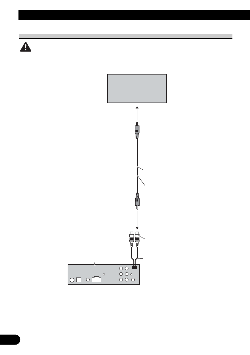
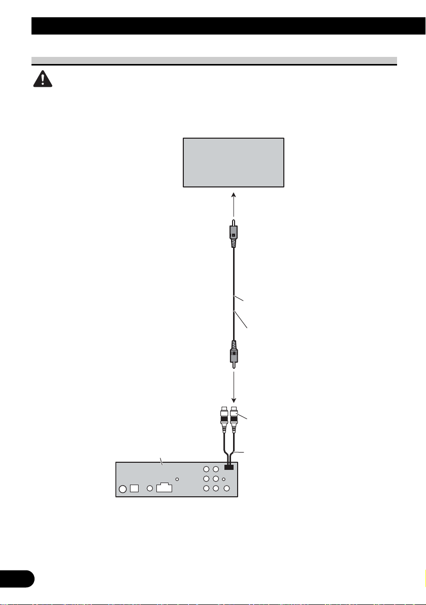
When using a display connected video outputs
WARNING
Never install the display in a location where it is visible to the driver while driving.
Display with
RCA input jacks
To video input
1.5 m
RCA cable
(supplied)
Video output
(VIDEO OUTPUT)
This product
15 cm
10
English Español Deutsch
Français Italiano Nederlands
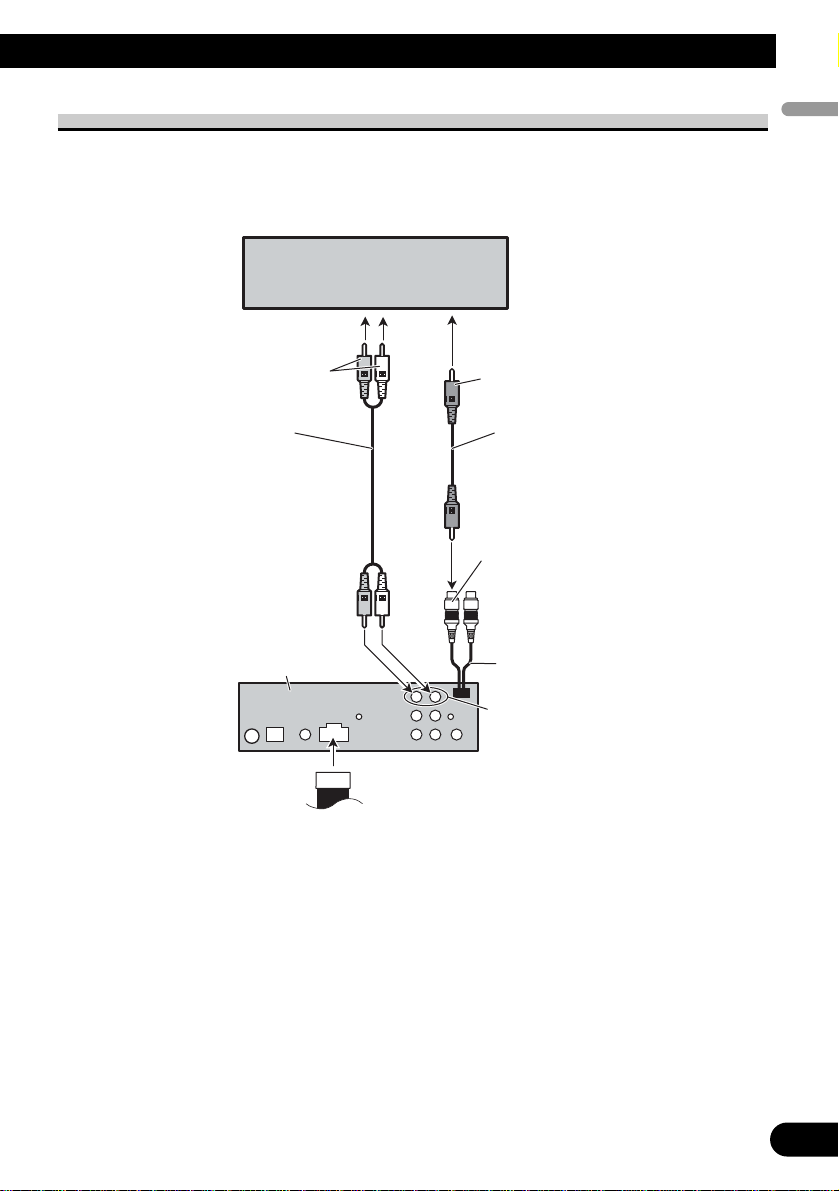
When connecting the external video component
It is necessary to set VIDEO IN to EXT-VIDEO in initial settings when connecting the
external video component.
External video component
(sold separately)
To audio output
RCA cable
(sold separately)
This product
To video output
RCA cable
(sold separately)
Video input
(VIDEO INPUT)
15 cm
Audio input
11
Installation
Rubber bush
Screw
Dashboard
Mounting sleeve
Note:
•Check all connections and systems before final
installation.
• Do not use unauthorized parts. The use of
unauthorized parts may cause malfunctions.
•Consult with your dealer if installation requires
drilling of holes or other modifications of the
vehicle.
•Do not install this unit where:
— it may interfere with operation of the vehicle.
— it may cause injury to a passenger as a result
of a sudden stop.
• The semiconductor laser will be damaged if it
overheats. Install this unit away from hot places
such as near the heater outlet.
•Optimum performance is obtained when the unit
is installed at an angle of less than 30°.
•When installing, to ensure proper heat dispersal
when using this unit, make sure you leave ample
space behind the rear panel and wrap any loose
cables so they are not blocking the vents.
DIN Front/Rear-mount
This unit can be properly installed either from
“Front” (conventional DIN Front-mount) or
“Rear” (DIN Rear-mount installation, utilizing
threaded screw holes at the sides of unit chassis).
For details, refer to the following installation
methods.
DIN Front-mount
Installation with the rubber bush
1. Insert the mounting sleeve into the dashboard.
•When installing in a shallow space, use a supplied mounting sleeve. If there is enough
space behind the unit, use factory supplied
mounting sleeve.
2. Secure the mounting sleeve by using a screwdriver to bend the metal tabs (90°) into place.
3. Install the unit as illustrated.
53
182182
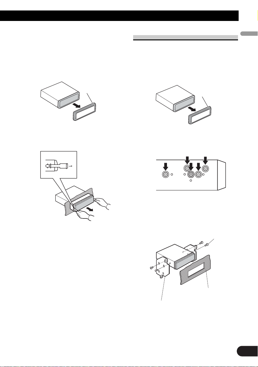
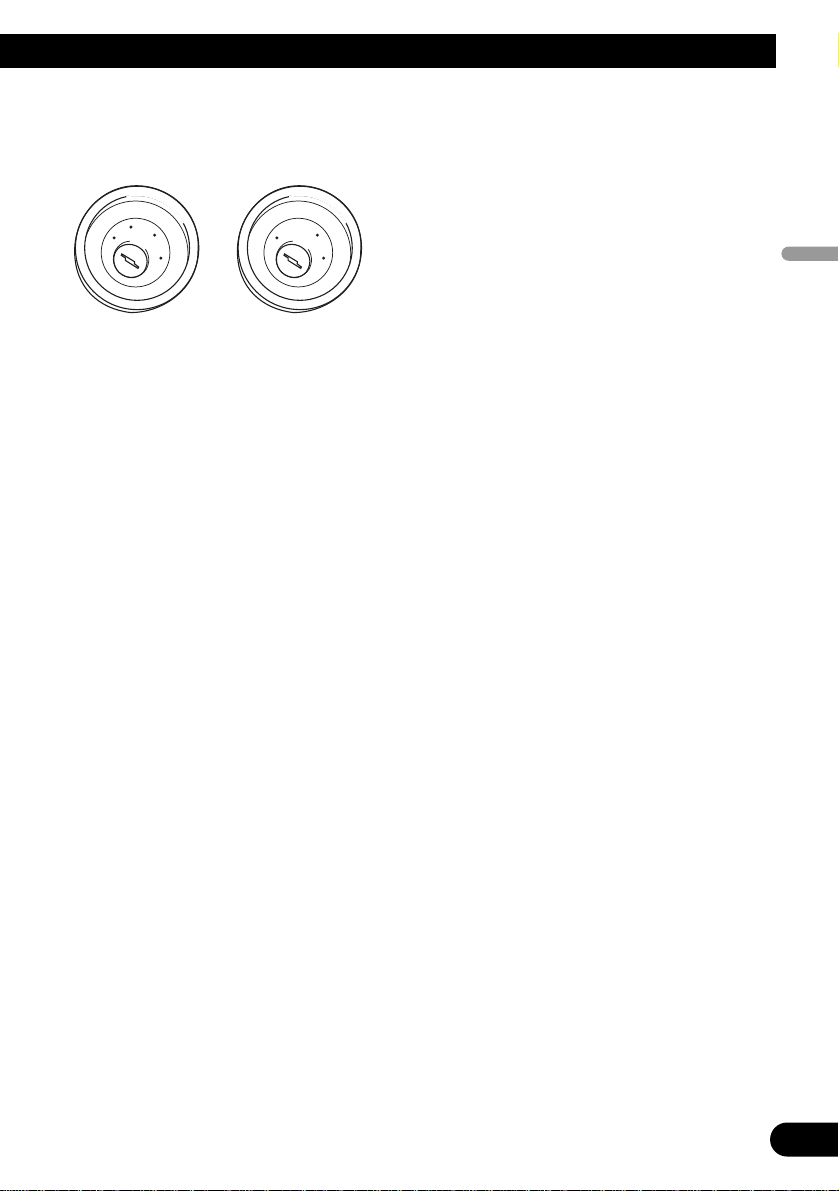
Removing the Unit
1. Extend top and bottom of the trim ring outwards
to remove the trim ring. When reattaching the
trim ring, push the trim ring onto the unit until it
clicks. (If the trim ring is attached upside down,
the trim ring will not fit properly.)
• It becomes easy to remove the trim ring if the
front panel is released.
2. Insert the supplied extraction keys into both sides
of the unit until they click into place.
3. Pull the unit out of the dashboard.
DIN Rear-mount
1. Extend top and bottom of the trim ring outwards
to remove the trim ring. When reattaching the
trim ring, push the trim ring onto the unit until it
clicks. (If the trim ring is attached upside down,
the trim ring will not fit properly.)
• It becomes easy to remove the trim ring if the
front panel is released.
2. Determine the appropriate position where the
holes on the bracket and the side of the unit
match.
3. Tighten two screws on each side.
• Use either truss screws (5 mm × 8 mm) or
flush surface screws (5 mm × 9 mm), depending on the shape of screw holes in the
bracket.
12
Trim ring
English Español Deutsch
Français Italiano Nederlands
Trim ring
Screw
Dashboard or Console
Factory radio mounting bracket

1
Conexión de las unidades ........................ 1
Conexión del cable de alimentación .................. 3
Conexión al amplificador de potencia vendido
separadamente ............................................ 5
Cuando conecte con un procesador
multicanal .................................................. 7
Conexión e instalación de la caja de conexión
de cable óptico ............................................ 8
Cuando utilice una pantalla
conectada a las salidas de vídeo ................ 9
Cuando conecte un componente de vídeo
externo ...................................................... 10
Instalación ................................................ 11
Montaje delantero/trasero DIN ........................ 11
Montaje delantero DIN .................................... 11
Montaje trasero DIN ........................................ 12
Conexión de las unidades
Contenido
ADVERTENCIA
• Para evitar el riesgo de accidentes e violación
potencial de las leyes aplicables, no se debe usar
nunca la función de DVD o TV frontal (vendido
separadamente) mientras el vehículo esté siendo
conducido. Igualmente, los monitores traseros no
deben quedarse en un sitio donde puedan causar
una distracción visible al conductor.
•En algunos países o estados, puede ser ilícita la
visualización de imágenes en un display dentro de
un vehículo, incluso por otras personas que no
sean el conductor. En los casos en que resulten
aplicables, estas normas deben respetarse y no
deben usarse las funciones de DVD de esta
unidad.
PRECAUCIÓN
• PIONEER no recomienda que sea usted mismo
quien instale o revise su pantalla. La instalación o
revisión del producto puede exponerle a
descargas eléctricas u otros peligros. Solicite que
todos los trabajos de instalación y revisión de su
pantalla los realice el personal de servicio Pioneer
autorizado.
• Fije todo el cableado con abrazaderas de cable o
con cinta adesiva. No permita que cualquier hilo
desnudo permanezca expuesto.
•No taladre un agujero en el compartimiento del
motor para conectar el cable amarillo de la unidad
a la batería del vehículo. La vibración del motor
podría estropear el aislamiento en el punto por
donde el cable pasa del compartimiento de los
pasajeros al compartimiento del motor. Tenga
mucho cuidado para mantener el buen estado del
cable en lo relativo a este punto.
•Es peligrosísimo dejar que el cable de la pantalla
se enrolle en la base del volante o en la palanca
de cambios. Asegúrese de instalar la pantalla de
forma que ésta no sea un obstáculo para la
conducción.
•Asegúrese de que los cables no interfieran con
partes móviles del vehículo tales como la palanca
de cambio, el freno de mano o el mecanismo de
deslizamiento de los asientos.
•No acorte ningún cable. Si lo hace, el circuito de
protección tal vez no funcione correctamente.
English
Español Deutsch
Français Italiano Nederlands
Nota:
• Esta unidad no se puede instalar en un
vehículo que no dispone de la posición ACC
(accesorio) en el interruptor de encendido.
•El uso de esta unidad en condiciones diferentes
de las siguientes podría causar un fuego o fallo de
funcionamiento.
—Vehículos con una batería de 12 voltios y
puesta a tierra negativa.
—Altavoz con 50 W (valor de salida) y de 4 a 8
ohmios (valor de impedancia).
• Para prevenir cortocircuitos, sobrecalentamiento
o fallo de funcionamiento, asegúrese de seguir las
instrucciones a continuación.
—Desenchufe el terminal negativo de la batería
antes de la instalación.
— Fije el cableado con abrazaderas de cable o
con cinta adhesiva. Para proteger el cableado,
envuélvalo con cinta adhesiva donde el
cableado se apoya sobre piezas metálicas.
— Posicione todos los cables alejados de las
piezas móviles, como el cambio de marchas y
rieles de los asientos.
—Posicione todos los cables alejados de lugares
calientes como cerca de la salida del
calentador.
—No pase el cable amarillo a través de un
agujero en el compartimiento del motor para
conectar la batería.
—Cubra cualquier conector de cable
desconectado con cinta de aislamiento.
—No extraiga las tapas RCA si no se utilizan los
cables RCA.
—No acorte ningún cable.
—No corte nunca el aislamiento del cable de
alimentación de esta unidad para compartir la
energía con otro equipo. La capacidad de
corriente del cable es limitada.
—Utilice un fusible con la capacidad
especificada.
—No conecte nunca el cable negativo de altavoz
directamente a la puesta a tierra.
—No junte nunca múltiples cables negativos de
altavoz.
• La señal de control se emite a través del cable
azul/blanco cuando se enciende esta unidad.
Conéctelo a un terminal de control de sistema de
amplificador de potencia externo o al terminal de
control de relé de antena automática del vehículo
(máx. 300 mA, 12 V CC). Si el vehículo está
equipado con una antena de vidrio, conéctelo al
terminal de suministro de potencia de refuerzo de
la antena.
•No conecte nunca el cable azul/blanco al terminal
de alimentación de un amplificador de potencia
externo. Igualmente, no conéctelo nunca al
terminal de alimentación de la antena automática.
De lo contrario, puede ocurrir la descarga de la
batería o un fallo de funcionamiento.
• Los conectores IP-BUS están codificados en
colores. Asegúrese de conectar los conectores del
mismo color.
• El cable negro es para la puesta a tierra. Se debe
conectar este cable y el cable de puesta a tierra de
otro producto (especialmente de productos de alta
corriente como un amplificador de potencia)
separadamente. De lo contrario, puede ocurrir un
fuego o fallo de funcionamiento si los cables se
sueltan accidentalmente.
Sin posición ACCPosición ACC
2
C
C
A
O
F
N
F
O
S
T
A
R
T
O
F
N
F
O
S
T
A
R
T
3
Conexión de las unidades
1*
2*
4*
3*
5*
Nota:
Dependiendo del tipo de vehículo, la
función de 3* y 5* puede ser diferente. En
este caso, asegúrese de conectar 2* a 5* y
4* a 3*.
Conecte los conductores del
mismo color uno a otro.
Tapa (1*)
No quite la tapa cuando
no se utiliza este
terminal.
Amarillo (3*)
Reserva
(o accesorio)
Rojo (5*)
Accesorio
(o reserva)
Amarillo (2*)
Conecte el terminal de
suministro de 12 V constante.
Rojo (4*)
Conecte al terminal controlado
por del interruptor de encendido
(12 V CC).
Conector ISO
Nota:
En algunos vehículos, el conector ISO
puede estar dividido en dos partes.
En este caso, asegúrese de conectar a
ambos conectores.
Hilos de altavoz
Blanco: Izquierda delantera +
Blanco/negro: Izquierda delantera ≠
Gris: Derecha delantera +
Gris/negro: Derecha delantera ≠
Verde: Izquierda trasera +
Verde/negro: Izquierda trasera ≠
Violeta: Derecha trasera +
Violeta/negro: Derecha trasera ≠
Negro (masa de la carrocería)
Conecte a un punto de metal limpio, libre de pintura.
Fusible (10 A)
Resistencia de fusible
Cuando conecte el procesador multicanal (DEQP6600) vendido separadamente a esta unidad, no
conecte nada a los conductores de los altavoces y al
control remoto del sistema (azul/blanco).
Conexión del cable de alimentación
English
Español Deutsch
Français Italiano Nederlands
4
Azul/blanco
Conecte al terminal de control de sistema del
amplificador de potencia (máx. 300 mA 12 V CC).
Azul/blanco (7*)
Conecte al terminal de
control de relé de antena
automática (máx. 300 mA
12 V CC).
La posición de los contactos del conector ISO
difiere dependiendo del tipo del vehículo. Conecte
6* y 7* cuando el contacto 5 es del tipo de control
de antena. En otros tipos de vehículo, no conecte
nunca 6* y 7*.
Amarillo/negro
Si se utiliza un equipo con función de silenciamiento,
conecte este conductor con el conductor de
silenciamiento de audio en tal equipo. Si no, mantenga el
enmudecimiento de audio libre de cualquier conexión.
Este producto
Entrada remota cableada
Se puede conectar el adaptador
de control remoto cableado
(vendido separadamente).
Entrada IP-BUS
(Azul)
Toma de antena
Azul/blanco (6*)
5
Conexión de las unidades
Salida trasera
Salida delantera
Azul/blanco
Conecte al terminal de control de sistema del
amplificador de potencia (máx. 300 mA 12 V CC).
Azul/blanco (7*)
Conecte al terminal de control de relé de
antena automática (máx. 300 mA 12 V CC).
La posición de los contactos del conector
ISO difiere dependiendo del tipo del
vehículo. Conecte 6* y 7* cuando el
contacto 5 es del tipo de control de antena.
En otros tipos de vehículo, no conecte
nunca 6* y 7*.
Azul/blanco (6*)
Cuando conecte el procesador multicanal
(DEQ-P6600) vendido separadamente a esta unidad,
no conecte nada a los conductores de los altavoces y
al control remoto del sistema (azul/blanco).
Nota:
Cuando conecte el procesador multicanal a esta
unidad, se debe conectar el amplificador de potencia
vendido separadamente al procesador multicanal.
Este producto
Conexión al amplificador de potencia vendido separadamente

English
Español Deutsch
Français Italiano Nederlands
6
Conecte los cables RCA
(vendidos separadamente)
Realice estas conexiones cuando
utilice el amplificador opcional.
Amplificador de
potencia (vendido
separadamente)
Amplificador de
potencia (vendido
separadamente)
Control remoto de sistema
Altavoz
delantero
Altavoz
delantero
+
≠
+
≠
+
≠
+
≠
Izquierda Derecha
Altavoz traseroAltavoz trasero
7
Conexión de las unidades
Cuando conecte con un procesador multicanal
Pantalla de visualización
de sistema de AV
Azul
Cable IP-BUS
(suministrado con el
procesador multicanal)
A la entrada de vídeo
Este producto
Salida DEQ
Azul
Cable RCA
(suministrado con el
procesador multicanal)
1,5 m
Cable RCA
(suministrado)
Salida de vídeo
(VIDEO OUTPUT)
15 cm
Caja de conexión de cable
óptico (suministrada con el
procesador multicanal)
Cable óptico
(suministrado con el
procesador multicanal)
Azul
Negro
Negro
Procesador Multicanal
(DEQ-P6600)
(vendido separadamente)
Negro
Conexión e instalación de la caja
de conexión de cable óptico
ADVERTENCIA
•Evite instalar esta unidad en lugares donde la
misma pueda obstruir la operación de los
dispositivos de seguridad como el airbag. De lo
contrario, hay el peligro de un accidente fatal.
•Evite instalar esta unidad en lugares donde la
misma pueda obstruir la operación del freno. De lo
contrario, esto podría causar un accidente de
tráfico.
• Fije esta unidad firmemente con la cinta de
gancho y bucle o atadura de fijación. Si esta
unidad está floja, puede estorbar la estabilidad de
conducción, lo que podría causar un accidente de
tráfico.
PRECAUCIÓN
• Instale esta unidad utilizando solamente las piezas
suministradas con la misma. Si se utilizan otras
piezas, la unidad podría dañarse o desmontarse, lo
que causaría un accidente u otros problemas.
•No instale esta unidad cerca de las puertas donde
el agua de la lluvia podría derramar sobre la
unidad. La penetración de agua en la unidad puede
causar el humo o fuego.
Conexión del cable óptico
1. Conecte el cable óptico y hilo de
tierra a la unidad principal.
Conecte el cable óptico de manera que
no se sobresalga de la unidad, como se
muestra en la ilustración. Apriete el
hilo de tierra a la protuberancia en la
parte posterior de la unidad.
2.
Conecte el cable óptico a la caja
de conexión de cable óptico.
Instalación de la caja de conexión
de cable óptico
•Cuando instale la caja de
conexión de cable óptico con la
cinta de gancho y bucle.
Instale la caja de conexión de cable
óptico usando la cinta de gancho y
bucle en el espacio ancho de la caja de
la consola.
•Cuando instale la caja de
conexión de cable óptico con la
atadura de fijación.
Envuelva el cable óptico y la caja de
conexión con la cinta protectora y
apriete con el cable de alimentación
usando la atadura de fijación.
8
English
Español Deutsch
Français Italiano Nederlands
Tornillo
Cinta de gancho
Cinta de bucle
Envuelva con la cinta protectora
Apriete con la atadura de fijación
Cable óptico
9
Conexión de las unidades
Cuando utilice una pantalla conectada a las salidas de vídeo
ADVERTENCIA
No instale nunca la pantalla en un lugar donde quede visible al conductor durante la conducción
del vehículo.
Pantalla con tomas
de entrada RCA
A la entrada de vídeo
1,5 m
Cable RCA
(suministrado)
Salida de vídeo
(VIDEO OUTPUT)
Este producto
15 cm
10
English
Español Deutsch
Français Italiano Nederlands
Cuando conecte un componente de vídeo externo
Se requiere ajustar VIDEO IN a EXT-VIDEO en el ajuste inicial cuando se conecta un
componente de vídeo externo.
Componente de vídeo externo
(vendido separadamente)
A la salida de audio
Cable RCA
(vendido separadamente)
Este producto
A la salida de vídeo
Cable RCA
(vendido separadamente)
Entrada de vídeo
(VIDEO INPUT)
15 cm
Entrada de audio
 Loading...