


DVD Recorder
DVR-920H
™
™
Operating Instructions
Thank you for buying this Pioneer product.
Please read through these operating instructions so you will know how to operate your model properly. After you have finished reading the instructions, put them away in a safe place for future reference.
IMPORTANT
CAUTION
RISK OF ELECTRIC SHOCK
DO NOT OPEN
The lightning flash with arrowhead symbol, within an equilateral triangle, is intended to alert the user to the presence of uninsulated "dangerous voltage" within the product's enclosure that may be of sufficient magnitude to constitute a risk of electric shock to persons.
CAUTION:
TO PREVENT THE RISK OF ELECTRIC SHOCK, DO NOT REMOVE COVER (OR BACK). NO USER-SERVICEABLE PARTS INSIDE. REFER SERVICING TO QUALIFIED SERVICE PERSONNEL.
The exclamation point within an equilateral triangle is intended to alert the user to the presence of important operating and maintenance (servicing) instructions in the literature accompanying the appliance.
D3-4-2-1-1_En-A
WARNING
This equipment is not waterproof. To prevent a fire or shock hazard, do not place any container filed with liquid near this equipment (such as a vase or flower pot) or expose it to dripping, splashing, rain or moisture.
WARNING
Before plugging in for the first time, read the following section carefully.
The voltage of the available power supply differs according to country or region. Be sure that the power supply voltage of the area where this unit will be used meets the required voltage (e.g., 230V or 120V) written on the rear panel.
CAUTION
This product is a class 1 laser product, but this product contains a laser diode higher than Class 1. To ensure continued safety, do not remove any covers or attempt to gain access to the inside of the product. Refer all servicing to qualified personnel.
The following caution label appears on your unit. Location: inside of the unit
CLASS 1
LASER PRODUCT
D3-4-2-1-8_A_En
This product complies with the Low Voltage Directive (73/23/EEC, amended by 93/68/EEC), EMC Directives (89/336/EEC, amended by 92/31/EEC and 93/68/EEC).
CAUTION
The STANDBY/ON switch on this unit will not completely shut off all power from the AC outlet. Since the power cord serves as the main disconnect device for the unit, you will need to unplug it from the AC outlet to shut down all power. Therefore, make sure the unit has been installed so that the power cord can be easily unplugged from the AC outlet in case of an accident. To avoid fire hazard, the power cord should also be unplugged from the AC outlet when left unused for a long period of time (for example, when on vacation).

WARNING
To prevent a fire hazard, do not place any naked flame sources (such as a lighted candle) on the equipment.
Operating Environment
Operating environment temperature and humidity: +5 ºC – +35 ºC (+41 ºF – +95 ºF); less than 85 %RH (cooling vents not blocked)
Do not install this unit in a poorly ventilated area, or in locations exposed to high humidity or direct sunlight (or strong artificial light)
VENTILATION CAUTION
When installing this unit, make sure to leave space around the unit for ventilation to improve heat radiation (at least 10 cm at top, 10 cm at rear, and 10 cm at each side).
WARNING
Slots and openings in the cabinet are provided for ventilation to ensure reliable operation of the product, and to protect it from overheating. To prevent fire hazard, the openings should never be blocked or covered with items (such as newspapers, table-cloths, curtains) or by operating the equipment on thick carpet or a bed.
This product incorporates copyright protection technology that is protected by method claims of certain U.S. patents and other intellectual property rights owned by Macrovision Corporation and other rights owners. Use of this copyright protection technology must be authorized by Macrovision Corporation, and is intended for home and other limited viewing uses only unless otherwise authorized by Macrovision Corporation. Reverse engineering or disassembly is prohibited.
This product is for general household purposes. Any failure due to use for other than household purposes (such as longterm use for business purposes in a restaurant or use in a car or ship) and which requires repair will be charged for even during the warranty period.
This product includes FontAvenue®
corporation. FontAvenue is a registered trademark of NEC
Corporation.
If the AC plug of this unit does not match the AC outlet you want to use, the plug must be removed and appropriate one fitted. Replacement and mounting of an AC plug on the power supply cord of this unit should be performed only by qualified service personnel. If connected to an AC outlet, the cut-off plug can cause severe electrical shock. Make sure it is properly disposed of after removal.
The equipment should be disconnected by removing the mains plug from the wall socket when not left unused for a long period of time (for example, when on vacation).
POWER-CORD CAUTION
Handle the power cord by the plug. Do not pull out the plug by tugging the cord and never touch the power cord when your hands are wet as this could cause a short circuit or electric shock. Do not place the unit, a piece of furniture, etc., on the power cord, or pinch the cord. Never make a knot in the cord or tie it with other cords. The power cords should be routed such that they are not likely to be stepped on. A damaged power cord can cause a fire or give you an electrical shock. Check the power cord once in a while. When you find it damaged, ask your nearest PIONEER authorized service center or your dealer for a replacement.
Replacement and mounting of an AC plug on the power supply cord of this unit should be performed only by qualified service personnel.
IMPORTANT |
The cut-off plug should be disposed of and must |
Do not connect either wire to the earth terminal of a |
||
not be inserted into any 13 amp socket as this can |
three pin plug. |
|||
result in electric shock. The plug or adaptor or the |
NOTE |
|||
FOR USE IN THE UNITED |
distribution panel should be provided with 5 A fuse. |
|||
As the colours of the wires in the mains lead of this |
After replacing or changing a fuse, the fuse cover in |
|||
KINGDOM |
||||
appliance may not correspond with coloured |
the plug must be replaced with a fuse cover which |
|||
The wires in this mains lead are coloured in |
markings identifying the terminals in your plug, |
corresponds to the colour of the insert in the base |
||
accordance with the following code: |
proceed as follows ; |
of the plug or the word that is embossed on the |
||
Blue |
: Neutral |
The wire which is coloured blue must be connected |
base of the plug, and the appliance must not be |
|
Brown |
: Live |
to the terminal which is marked with the letter N or |
used without a fuse cover. If lost replacement fuse |
|
If the plug provided is unsuitable for your socket |
coloured black. |
covers can be obtained from your dealer. |
||
outlets, the plug must be cut off and a suitable plug |
The wire which is coloured brown must be |
Only 5 A fuses approved by B.S.I or A.S.T.A to |
||
fitted. |
|
connected to the terminal which is marked with the |
B.S.1362 should be used. |
|
|
|
letter L or coloured red. |
D3-4-2-1-2-2_En |
|

Contents
Contents
01 Before you start
Features . . . . . . . . . . . . . . . . . . . . . . . . . . . . . . . . . . . 6 What’s in the box . . . . . . . . . . . . . . . . . . . . . . . . . . . . 8
Putting the batteries in the remote control . . . . . . . . . 8
Using the remote control . . . . . . . . . . . . . . . . . . . . . . 8
Disc / content format playback compatibility . . . . . . . 9 About the internal hard disk drive. . . . . . . . . . . . . . . 11
05 Using the GUIDE Plus+™ electronic program guide
The GUIDE Plus+ System. . . . . . . . . . . . . . . . . . . . . 40 Using GUIDE Plus+ . . . . . . . . . . . . . . . . . . . . . . . . . 40 Areas . . . . . . . . . . . . . . . . . . . . . . . . . . . . . . . . . . . . 42
GUIDE Plus+ FAQ and troubleshooting . . . . . . . . . . 49
02 Connecting up
Rear panel connections . . . . . . . . . . . . . . . . . . . . . . 12 Front panel connections . . . . . . . . . . . . . . . . . . . . . . 12
Extra features for use with compatible TVs . . . . . . . . 13
Easy connections . . . . . . . . . . . . . . . . . . . . . . . . . . . 14
Using other types of audio/video output . . . . . . . . . . 15 Connecting to a cable box, satellite receiver or
digital terrestrial receiver . . . . . . . . . . . . . . . . . . . . . 16 Connecting an external decoder box (1) . . . . . . . . . . 17 Connecting an external decoder box (2) . . . . . . . . . . 18 Connecting to an AV amplifier/receiver . . . . . . . . . . 19
Connecting using HDMI . . . . . . . . . . . . . . . . . . . . . . 20 About HDMI . . . . . . . . . . . . . . . . . . . . . . . . . . . . . . . 20
Connecting other AV sources . . . . . . . . . . . . . . . . . . 21
Plugging in. . . . . . . . . . . . . . . . . . . . . . . . . . . . . . . . 21
03 Controls and displays
Front panel . . . . . . . . . . . . . . . . . . . . . . . . . . . . . . . . 22 Display . . . . . . . . . . . . . . . . . . . . . . . . . . . . . . . . . . . 23 Remote control. . . . . . . . . . . . . . . . . . . . . . . . . . . . . 24
04 Getting started
Switching on and setting up . . . . . . . . . . . . . . . . . . . 26 Setting up the GUIDE Plus+ system. . . . . . . . . . . . . 29 Selecting the hard disk or DVD for playback and recording . . . . . . . . . . . . . . . . . . . . . . . . . . . . . . . . . 31
Making your first recording. . . . . . . . . . . . . . . . . . . . 32 Using the built-in TV tuner . . . . . . . . . . . . . . . . . . . . 33
Basic playback . . . . . . . . . . . . . . . . . . . . . . . . . . . . . 34 Using the Home Menu . . . . . . . . . . . . . . . . . . . . . . . 37
Displaying disc information on-screen . . . . . . . . . . . 37
06 Playback
Introduction . . . . . . . . . . . . . . . . . . . . . . . . . . . . . . . 51
Using the Disc Navigator to browse the contents
of a disc.. . . . . . . . . . . . . . . . . . . . . . . . . . . . . . . . . . 51
Navigating discs and the HDD . . . . . . . . . . . . . . . . . 53
Scanning discs. . . . . . . . . . . . . . . . . . . . . . . . . . . . . 53 Playing in slow motion . . . . . . . . . . . . . . . . . . . . . . . 54
Frame advance/frame reverse . . . . . . . . . . . . . . . . . 54
The Play Mode menu . . . . . . . . . . . . . . . . . . . . . . . . 55
Displaying and switching subtitles . . . . . . . . . . . . . . 58 Switching DVD soundtracks . . . . . . . . . . . . . . . . . . . 58 Switching audio channels . . . . . . . . . . . . . . . . . . . . 58
Switching camera angles . . . . . . . . . . . . . . . . . . . . . 59
07 Recording
About DVD recording . . . . . . . . . . . . . . . . . . . . . . . . 60 About HDD recording. . . . . . . . . . . . . . . . . . . . . . . . 60
Recording time and picture quality. . . . . . . . . . . . . . 60 Restrictions on video recording . . . . . . . . . . . . . . . . 61 Setting the picture quality/recording time . . . . . . . . 61 Basic recording from the TV . . . . . . . . . . . . . . . . . . . 62
Setting a timer recording . . . . . . . . . . . . . . . . . . . . . 63 Timer recording FAQ . . . . . . . . . . . . . . . . . . . . . . . . 66
Simultaneous recording and playback . . . . . . . . . . . 66 Recording from an external component . . . . . . . . . . 67 Recording from a DV camcorder . . . . . . . . . . . . . . . 68 Recording from the DV output . . . . . . . . . . . . . . . . . 69 Playing your recordings on other DVD players . . . . . 69 Initializing a DVD-RW disc . . . . . . . . . . . . . . . . . . . . 70
4
En

Contents
08 Copying and back-up
Introduction. . . . . . . . . . . . . . . . . . . . . . . . . . . . . . . 71
One Touch Copy (HDD to DVD) . . . . . . . . . . . . . . . . 72 One Touch Copy (DVD to HDD) . . . . . . . . . . . . . . . . 73
Copying from HDD to DVD . . . . . . . . . . . . . . . . . . . 73
HDD to DVD Copy List menu options. . . . . . . . . . . . 74
Recording the Copy List. . . . . . . . . . . . . . . . . . . . . . 75
HDD to DVD Copy List commands. . . . . . . . . . . . . . 75
Copying from DVD to HDD . . . . . . . . . . . . . . . . . . . 81
DVD to HDD Copy List menu options. . . . . . . . . . . . 82
Recording the Copy List. . . . . . . . . . . . . . . . . . . . . . 82
DVD to HDD Copy List commands. . . . . . . . . . . . . . 83
Using disc back-up . . . . . . . . . . . . . . . . . . . . . . . . . 84
09 Editing
The Disc Navigator screen . . . . . . . . . . . . . . . . . . . . 86 Disc Navigator menu options . . . . . . . . . . . . . . . . . 88 Editing VR mode Original, Video mode and
HDD content . . . . . . . . . . . . . . . . . . . . . . . . . . . . . . 89 Editing HDD groups. . . . . . . . . . . . . . . . . . . . . . . . . 93
Creating and editing a VR mode Play List . . . . . . . . 94
10 Disc History
Using the Disc History . . . . . . . . . . . . . . . . . . . . . . . 99
11 The PhotoViewer
Playing a slideshow . . . . . . . . . . . . . . . . . . . . . . . . 100
12 The Disc Setup menu |
|
Basic settings . . . . . . . . . . . . . . . . . . . . . . . . . . . . |
102 |
Initialize settings . . . . . . . . . . . . . . . . . . . . . . . . . . |
103 |
Finalize settings . . . . . . . . . . . . . . . . . . . . . . . . . . . |
103 |
Optimize HDD . . . . . . . . . . . . . . . . . . . . . . . . . . . . |
103 |
HDD Initialize . . . . . . . . . . . . . . . . . . . . . . . . . . . . |
103 |
13 The Video/Audio Adjust menu
Setting the picture quality for TV and external
inputs . . . . . . . . . . . . . . . . . . . . . . . . . . . . . . . . . . 104
Setting the picture quality for disc playback . . . . . 105
Audio DRC. . . . . . . . . . . . . . . . . . . . . . . . . . . . . . . 106
14 The Initial Setup menu
Using the Initial Setup menu . . . . . . . . . . . . . . . . . 107
Basic settings . . . . . . . . . . . . . . . . . . . . . . . . . . . . 107 Tuner settings . . . . . . . . . . . . . . . . . . . . . . . . . . . . 109 Video In / Out settings . . . . . . . . . . . . . . . . . . . . . . 111 Audio In settings . . . . . . . . . . . . . . . . . . . . . . . . . . 113 Audio Out settings. . . . . . . . . . . . . . . . . . . . . . . . . 114 Language settings . . . . . . . . . . . . . . . . . . . . . . . . . 115 Recording settings . . . . . . . . . . . . . . . . . . . . . . . . 117 Playback settings. . . . . . . . . . . . . . . . . . . . . . . . . . 118 HDMI Output . . . . . . . . . . . . . . . . . . . . . . . . . . . . . 121
15 Additional information
Resetting the recorder . . . . . . . . . . . . . . . . . . . . . . 123
Setting up the remote to control your TV . . . . . . . . 123 Screen sizes and disc formats . . . . . . . . . . . . . . . . 124
Troubleshooting. . . . . . . . . . . . . . . . . . . . . . . . . . . 125
Frequently asked questions . . . . . . . . . . . . . . . . . . 128
About DV . . . . . . . . . . . . . . . . . . . . . . . . . . . . . . . . 129 Manual recording modes. . . . . . . . . . . . . . . . . . . . 130 Language code list . . . . . . . . . . . . . . . . . . . . . . . . 131 Country code list . . . . . . . . . . . . . . . . . . . . . . . . . . 131
On-screen displays and recorder displays . . . . . . . 132
Handling discs. . . . . . . . . . . . . . . . . . . . . . . . . . . . 133 Storing discs . . . . . . . . . . . . . . . . . . . . . . . . . . . . . 133 Damaged discs . . . . . . . . . . . . . . . . . . . . . . . . . . . 134 Cleaning the pickup lens . . . . . . . . . . . . . . . . . . . . 134 Condensation . . . . . . . . . . . . . . . . . . . . . . . . . . . . 134 Hints on installation . . . . . . . . . . . . . . . . . . . . . . . 134 Moving the recorder . . . . . . . . . . . . . . . . . . . . . . . 134 Glossary. . . . . . . . . . . . . . . . . . . . . . . . . . . . . . . . . 135 Specifications . . . . . . . . . . . . . . . . . . . . . . . . . . . . 137
Index
English
5
En

01 Before you start
Chapter 1
Before you start
Features
• Built-in GUIDE Plus+™ electronic program guide
The GUIDE Plus+ system is an interactive on-screen TV programming guide. You can see what’s on TV today and in the coming week, search TV listings for certain categories of program or by your own keywords, and even set the recorder to record programs with the press of a single button.
• HDD recording HDD
You can record up to 433 hours of video (in SLP mode) on the internal 250GB (gigabyte) hard disk (HDD).
With both recordable DVD and a high-capacity HDD in the same recorder, you have the flexibility to keep recordings on the HDD for quick access anytime, or record to DVD for archiving or playing on other DVD players.
•Copy between HDD and DVD
You can copy recordings from the HDD to recordable DVD, or from DVD to the HDD. Usually you can use the high-speed copy feature, which can copy an hour of video in under two minutes (when recorded in EP mode using a DVD-R Ver. 2.0 / 8x disc).
You can also choose to copy material at a different recording quality from the original. For example, you might want to copy a FINE mode (highest quality) recording on the HDD to SP (standard play) quality on a DVD so that you can fit other recordings on the same disc.
•One Touch Copy
One Touch Copy makes copying the currently playing title from HDD to DVD, or DVD to HDD as simple as pressing a button.
• Chase play  HDD
HDD
Using chase play you can start watching a recording before the recording has finished. For example, you could set a timer recording for a program that you’re going to miss the first 15 minutes of, then start watching while the recorder is still recording the program 15 minutes ahead of you.
6
•Simultaneous recording and playback
VR mode |
HDD |
Playback and recording for both DVDs and the built-in hard disk drive (HDD) are completely independent. For example you can record a broadcast program to either a recordable DVD or the HDD, while watching another recording you already made on the same DVD or on the HDD.
•Disc Navigator
The on-screen Disc Navigator makes finding your way around the contents of a disc or the HDD easy. For recordable DVD and HDD content, moving thumbnail images are displayed for ease of use. The Disc Navigator is also where you can edit HDD and recordable DVD content.
•Disc History
The Disc History screen shows disc information, including how much free space remains for recording, for the last 30 recordable discs loaded in the recorder. Every time you load a recordable disc, the Disc History is automatically updated with the latest information.
•Home Menu
The Home Menu gives you on-screen access to all the recorder’s features in one convenient place, from setting up the recorder, to programming a timer recording and editing a recording.
•Progressive scan-compatible
Compared to standard interlaced video, progressive scan effectively doubles the amount of video information fed to your TV or monitor. The result is a stable, flicker-free image. (Check your TV/monitor for compatibility with this feature.)
•Cinema surround sound in your home
Connect this recorder to a Dolby Digital and/or DTScompatible AV amp/receiver to enjoy full surround sound effects from Dolby Digital and DTS DVD discs.
•Easy Timer Recording
Setting the recorder to record a program is simple from the Easy Timer Recording screen. Set the channel to record and the recording quality, then graphically set the start and end times of the recording. That’s it!
En

Before you start |
01 |
•Program up to 32 timer recordings
You can program the recorder to record up to 32 programs, up to a month in advance. As well as single programs, you can specify daily or weekly recordings, too.
This recorder is also compatible with VPS/PDC systems, which ensure you don’t miss a timer recording, even if the broadcast is not running to schedule.
•One Touch Recording
Use One Touch Recording to start recording immediately in 30 minute blocks. Each time you press the REC button, the recording time is extended by another 30 minutes.
•Optimized recording
Optimized recording adjusts the recording quality automatically if a timer recording will not fit onto a disc with the settings that you made.
•High quality 16-bit Linear PCM audio
When recording using one of the high quality record settings (FINE or MN32), the audio is recorded in uncompressed 16-bit Linear PCM format. This delivers great sounding audio to accompany the high picture quality.
•Picture quality adjustment features
During playback, you can adjust various picture quality settings to improve the picture. You can also adjust the recording picture quality. For example, if you want to make a DVD copy of an old video tape, you can optimize the picture quality before transferring it to disc.
•Find what you want to watch quickly and easily
Unlike video tape that needs to be wound to the correct place, you can jump right to the part of a DVD disc or the HDD that you want to watch. Search for a point on a disc by title, chapter or time.
•Manual recording
In addition to the five preset recording quality modes (FINE, SP, LP, EP and SLP), the manual recording mode allows you to access 32 different recording quality/time settings, giving you precise control over the recording.
•Record to and from a DV camcorder
This recorder has a built-in DV (Digital Video) input/ output jack for connection to a DV camcorder. This makes it ideal for transferring camcorder footage to DVD or HDD for editing. You can also transfer DVD or HDD content back to the camcorder if you need to.
• Safe, non-destructive editing 
When you edit a DVD-RW, the actual content of the disc (the Original content) is not touched. The edited version (the Play List content) just points to various parts of the Original content.
• Chapter marking VR mode |
HDD |
You can easily add chapter markers anywhere in your recordings for easy editing.
•Play Video mode recordings on a regular DVD
player 
Discs recorded using the Video mode can be played back on regular DVD players, including computer DVD drives
compatible with DVD-Video playback*.
* ‘DVD-Video format’ recording: The use of the DVDVideo format for recording on DVD-R and DVD-RW discs is referred to as recording in ‘Video mode’ on Pioneer’s DVD recorders. Supporting playback of DVD-R / DVDRW discs is optional for manufacturers of DVD playback equipment, and there is DVD playback equipment that does not play DVD-R or DVD-RW discs recorded in the DVD-Video format.
Note: ‘Finalization’ is required.
•WMA, MP3 and JPEG file playback
This recorder can play WMA and MP3 audio files and JPEG picture files on CD-R, CD-RW or CD-ROM discs.
•Disc Back-up
The disc back-up feature gives you a convenient way to back-up important material on DVD to another recordable DVD disc. The material is first copied to the HDD, then on to a second DVD disc.
• Recovery Recording HDD
When a timer recording is set to use DVD but the disc loaded at the time of the recording is unrecordable, the program will automatically be recorded to the HDD.
• Auto Replace Recording HDD
This feature is useful for regular timer recordings of a TV program which you don’t want to keep after watching. Each time the program is recorded, it replaces the one currently on the HDD. There’s no need to manually delete it later.
Note on copying:
Recording equipment should be used only for lawful copying and you are advised to check carefully what is lawful copying in the country in which you are making a copy. Copying of copyright material such as films or music is unlawful unless permitted by a legal exception or consented to by the rightowners.
English
7
En
01 Before you start
What’s in the box
Please confirm that the following accessories are in the box when you open it.
•Remote control
•AA/R6P dry cell batteries x2
•Audio/video cable (red/white/yellow)
•RF antenna cable
•G-LINK cable
•Power cable
•These operating instructions
•Warranty card
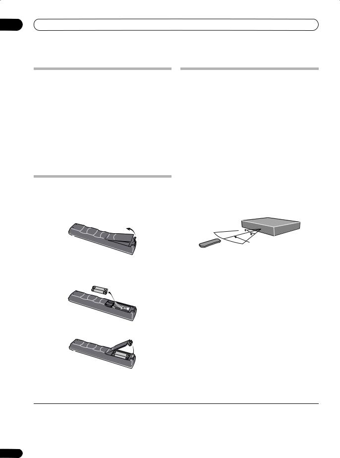
Putting the batteries in the remote control1
Using the remote control
Please keep in mind the following when using the remote control:
•Make sure that there are no obstacles between the remote and the remote sensor on the unit.
•Remote operation may become unreliable if strong sunlight or fluorescent light is shining on the unit’s remote sensor.
•Remote controllers for different devices can interfere with each other. Avoid using remotes for other equipment located close to this unit.
•Replace the batteries when you notice a fall off in the operating range of the remote.
•When the batteries run down or you change the batteries, the remote control mode and TV preset codes are automatically reset. See Remote Control Mode on page 109 and Setting up the remote to control your TV on page 123 to reset them.
1 Open the battery compartment cover on the back of the remote control.
• Use within the operating range and angle, as shown.
2 Insert two AA/R6P batteries into the battery compartment following the indications ( , ) inside the compartment.
3 Close the cover.
30

30
7m
•You can control this recorder using the remote sensor of another Pioneer component using the CONTROL IN jack on the rear panel. See Rear panel connections on page 12 for more information.
 Note
Note
1 Incorrect use of batteries can result in hazards such as leakage and bursting. Please observe the following:
•Don’t mix new and old batteries together.
•Don’t use different kinds of batteries together—although they may look similar, different batteries may have different voltages.
•Make sure that the plus and minus ends of each battery match the indications in the battery compartment.
•Remove batteries from equipment that isn’t going to be used for a month or more.
•When disposing of used batteries, please comply with governmental regulations or environmental public instruction’s rules that apply in your country or area.
8
En

Before you start
Disc / content format playback compatibility
General disc compatibility
This recorder is compatible with a wide range of disc types (media) and formats. Playable discs will generally feature one of the following logos on the disc and/or disc packaging. Note however that some disc types, such as recordable CD and DVD, may be in an unplayable format—see below for further compatibility information.
DVD-Video DVD-R DVD-RW
Note that older models of DVD recorders and DVD writers may reject DVD-RW Ver. 1.2 / 4x discs. If you want to share DVD-RW discs between this recorder and an older recorder/writer, we recommend using Ver. 1.1 discs.
The following table shows older Pioneer DVD recorders that are not fully compatible with DVD-RW Ver. 1.2 / 4x discs.
Model |
Playable |
Recordable |
DVR-7000 |
Yes1,2,3 |
No |
DVR-3100/ DVR-5100H |
Yes1 |
No |
1Discs should be finalized in this recorder before playing. Unfinalized VR mode and Video mode discs may not play.
2Cannot read the CPRM information will show in the display when you load a disc. However, this will not affect playback.
3Copy-once protected disc titles will not play.
Audio CD |
Video CD |
CD-R |
|
CD-RW |
|
|
|
|
|
|
|
|
|
|
|
|
|
|
|
|
|
|
|
|
|
|
|
|
|
|
|
|
|
|
Fujicolor CD
•Also compatible with KODAK Picture CD
• is a trademark of DVD Format/Logo Licensing Corporation.
• is a trademark of Fuji Photo Film Co. Ltd.
This recorder also supports the IEC’s Super VCD standard. Compared to the Video CD standard, Super VCD offers superior picture quality, and allows two soundtracks to be recorded. Super VCD also supports the widescreen size.
VIDEO

 CD
CD
Super Video CD (Super VCD)
DVD-R/RW compatibility
This recorder will play and record DVD-R/RW discs.
Compatible media:
•DVD-RW Ver. 1.1, Ver. 1.1 / 2x and Ver. 1.2 / 4x
•DVD-R Ver. 2.0 and Ver. 2.0 / 4x / 8x Recording formats:
•DVD-R: DVD-Video format (Video mode)
•DVD-RW: Video Recording (VR) format and DVDVideo format (Video mode)
CD-R/RW compatibility
This recorder cannot record CD-R or CD-RW discs.
•Compatible formats: CD-Audio, Video CD/Super VCD, ISO 9660 CD-ROM* containing MP3, WMA or JPEG files
*ISO 9660 Level 1 or 2 compliant. CD physical format: Mode1, Mode2 XA Form1. Romeo and Joliet file systems are both compatible with this recorder.
•Multi-session playback: Yes (except CD-Audio and Video CD/Super VCD)
•Unfinalized disc playback: CD-Audio only
Compressed audio compatibility
•Compatible media: CD-ROM, CD-R, CD-RW
•Compatible formats: MPEG-1 Audio Layer 3 (MP3), Windows Media Audio (WMA)
•Sampling rates: 44.1 or 48kHz
•Bit-rates: Any (128Kbps or higher recommended)
•Variable bit-rate (VBR) MP3 playback: Yes
•VBR WMA playback: No
•WMA encoder compatibility: Windows Media Codec 8 (files encoded using Windows Media Codec 9 may be playable but some parts of the specification are not supported; specifically, Pro, Lossless, Voice and VBR)
•DRM (Digital Rights Management) file playback: No (see also DRM in the Glossary on page 135)
•File extensions: .mp3, .wma (these must be used for the recorder to recognize MP3 and WMA files – do not use for other file types)
•File structure: Up to 99 folders / 999 files (if these limits are exceeded, only files and folders up to these limits are playable)
01
English
9
En

01 Before you start
WMA (Windows Media Audio) compatibility
The Windows Media® logo printed on the box indicates that this recorder can playback Windows Media Audio content.
WMA is an acronym for Windows Media Audio and refers to an audio compression technology developed by Microsoft Corporation. WMA content can be encoded by
using Windows Media® Player version 7, 7.1, Windows
Media® Player for Windows® XP, or Windows Media® Player 9 Series.
Microsoft, Windows Media, and the Windows logo are trademarks, or registered trademarks of Microsoft Corporation in the United States and/or other countries.
JPEG file compatibility
•Compatible formats: Baseline JPEG and EXIF 2.2* still image files
*File format used by digital still cameras
•Sampling ratio: 4:4:4, 4:4:2, 4:2:0
•Horizontal resolution: 160 – 5120 pixels
•Vertical resolution: 120 – 3840 pixels
•Progressive JPEG compatible: No
•File extensions: .jpg, jpeg, jif, jfif (must be used for the recorder to recognize JPEG files – do not use for other file types)
•File structure: The recorder can load up to 99 folders / 999 files at one time (if there are more files/folders that this on the disc then more can be reloaded)
PC-created disc compatibility
Discs recorded using a personal computer may not be playable in this unit due to the setting of the application software used to create the disc. In these particular instances, check with the software publisher for more detailed information.
Discs recorded in packet write mode (UDF format) are not compatible with this recorder.
Check the DVD-R/RW or CD-R/RW software disc boxes for additional compatibility information.
 Frequently asked questions
•What’s the difference between DVD-R and DVD-RW?
The most important difference between DVD-R and DVD-RW is that DVD-R is a record-once medium, while DVD-RW is a re-recordable/erasable medium. You can re-record/erase a DVD-RW disc approximately 1,000 times.
For more information, see About DVD recording on page 60.
•What’s VR mode?
VR (Video Recording) mode is a special mode designed for home DVD recording. It allows flexible editing of recorded material compared to ‘Video mode’. On the other hand, Video mode discs are more compatible with other DVD players.
•Can I play my recordable discs in a regular DVD player?
Generally, DVD-R discs and DVD-RW discs recorded in Video mode* are playable in a regular DVD player, but they must be ‘finalized’ first. This process fixes the contents of the disc to make them readable to other DVD players as DVD-Video discs.
DVD-RW discs recorded in VR mode are playable in some players.


 This label indicates playback compatibility with DVD-RW discs recorded in VR mode (Video Recording format). However, for discs recorded with a record-only-once encrypted program, playback can only be achieved using the CPRM compatible device.
Note that Pioneer cannot guarantee that discs recorded using this recorder will play on other players.
*‘DVD-Video format’ recording: The use of the DVDVideo format for recording on DVD-R and DVD-RW discs is referred to as recording in ‘Video mode’ on Pioneer’s DVD recorders. Supporting playback of DVD-R / DVDRW discs is optional for manufacturers of DVD playback equipment, and there is DVD playback equipment that does not play DVD-R or DVD-RW discs recorded in the DVD-Video format.
Note: ‘Finalization’ is required.
This recorder supports the recording of ‘copy-once’ broadcast programs using the CPRM copy protection system (see CPRM on page 61) on CPRM-compliant DVD-RW discs in VR mode. CPRM recordings can only be played on players that are specifically compatible with CPRM.
10
En
Before you start
•Do I need two DVD recorders for editing? What kind of editing can I do?
Unlike editing video tape, you only need one DVD recorder to edit discs. With DVD, you edit by making a ‘Play List’ of what to play and when to play it. On playback, the recorder plays the disc according to the Play List.
Original
Title 1 |
|
|
|
|
|
|
Title 2 |
|
Title 3 |
|
|
|
|||
|
|
|
|
|
|
|
|
|
|
|
|
|
|
|
|
|
|
|
|
|
|
|
|
|
|
|
|
|
|
|
|
Chapter 1 |
Chapter 2 |
Chapter 3 |
|
|
Chapter 1 |
|
|
Chapter 1 |
Chapter 2 |
|
|||||
|
|
|
|
|
|
|
|
|
|
|
|
|
|
|
|
|
|
|
|
|
|
|
|
|
|
|
|
|
|
|
|
Title 1 |
|
|
Title 2 |
|
|
|
||
|
|
|
|
|
|
|
|
|
Chapter 1 |
Chapter 2 |
|
Chapter 1 |
Chapter 2 |
||||
Play List
Throughout this manual, you will often see the words Original and Play List to refer to the actual content and the edited version.
•Original content refers to what’s actually recorded on the disc.
•Play List content refers to the edited version of the disc—how the Original content is to be played.
About the internal hard disk drive
The internal hard disk drive (HDD) is a fragile piece of equipment. Please use the recorder following the guidelines below to protect against possible HDD failure.
We recommend that you back up your important recordings onto DVD-R/RW discs in order to protect against accidental loss.
•Do not move the recorder while it is on.
•Install and use the recorder on a stable, level surface.
•Do not block the rear vent/cooling fan.
•Do not use the recorder in excessively hot or humid places, or in places that may be subject to sudden changes in temperature. Sudden changes in temperature can cause condensation to form inside the recorder. This can be a cause of HDD failure.
•While the recorder is switched on or the front panel display shows EPG, do not unplug from the wall socket or switch the electricity off from the breaker switch.
•Do not move the recorder immediately after switching it off or while the front panel display shows EPG. If you need to move the recorder, please follow the steps below:
1 After the message POWER OFF is shown in the display, wait at least two minutes.
2 Unplug from the wall socket.
3 Move the recorder.
•If there’s a power failure while the recorder is on there is a chance that some data on the HDD will be lost.
•The HDD is very delicate. If used improperly or in an unsuitable environment, it is possible that the HDD will fail after a few years of use. Signs of problems include playback unexpectedly freezing and noticeable block noise (mosaic) in the picture. However, sometimes there will be no warning signs of HDD failure.
If the HDD fails, no playback of recorded material will be possible. In this case it will be necessary to replace the HDD unit.
Optimizing HDD performance
As you record and edit material on the HDD, the data on the disk becomes fragmented, eventually affecting the recorder’s performance. Before this happens, the recorder will warn you that it is time to optimize the HDD (which you can do from the Disc Setup menu; see
Optimize HDD on page 103).
01
English
11
En

02 Connecting up
Chapter 2
Connecting up
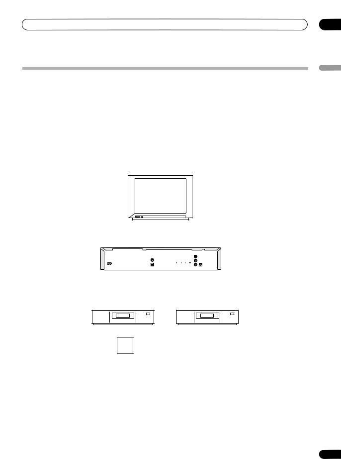
Rear panel connections
|
1 |
|
2 |
|
3 |
|
4 |
|
AV 2 (INPUT 1/DECODER) |
|
AV 1 (RGB) - TV |
|
|
ANTENNA |
|
|
|
|
|
|
|
|
|
|
|
|
|
|
COMPONENT |
|
IN |
|
|
|
|
|
VIDEO OUT |
|
|
|
|
|
|
|
Y |
|
|
AC IN |
COAXIAL |
|
IN PUT 3 |
|
|
|
|
|
|
|
|
PB |
|
|
|
|
|
|
|
|
|
|
|
|
|
|
|
|
PR |
IN |
G-LINK |
|
|
|
|
|
OUT |
||
|
OPTICAL |
HDMI OUT |
R AUDIO L |
VIDEO |
S-VIDEO |
CONTROL |
|
|
DIGITAL |
|
OUT PUT |
|
|
|
|
|
AUDIO OUT |
|
|
|
|
||
|
|
|
|
|
|
|
|
5 |
6 |
7 |
8 |
9 |
|
10 |
11 |
1AV2(INPUT 1/DECODER) AV connector
Audio/video input/output SCART-type AV connector for connecting to a VCR, or other equipment with a SCART connector. The input accepts video, S-video and RGB.
See AV2/L1 In on page 113 for how to set this up.
2AV1(RGB)-TV AV connector
Audio/video output SCART-type AV connector for connecting to a TV or other equipment with a SCART connector. The video output is switchable between video, S-video and RGB. See page AV1 Out on page 112 for how to set this up.
3 COMPONENT VIDEO OUT
A high-quality video output for connecting to a TV or monitor with a component video input.
9 OUTPUT
Stereo analog audio, video and S-video outputs for connection to a TV or AV amplifier/receiver.
10 CONTROL IN
Use to control this recorder from the remote sensor of another Pioneer component with a CONTROL OUT terminal and bearing the Pioneer mark. Connect the CONTROL OUT of the other component to the CONTROL IN of this recorder using a mini-plug cord.
11 G-LINK
Use to connect the supplied G-LINK cable to enable GUIDE Plus+ to control an external satellite receiver, etc.
4 ANTENNA IN/OUT
Connect your TV antenna to the ANTENNA IN jack. The signal is passed through to the ANTENNA OUT jack for connection to your TV.
5AC IN – Power inlet
6DIGITAL AUDIO OUT
Coaxial and optical digital audio jacks for connecting to an AV amplifier/receiver, Dolby Digital/DTS/MPEG decoder or other equipment with a digital input.
7 HDMI OUT
HDMI output providing a high quality interface for digital audio and video.
8 INPUT 3
Stereo analog audio, video and S-video inputs for connection to a VCR or other source component.
12
Front panel connections
DBY / ON |
S-VIDEO |
VIDEO |
AUDIO |
|
DV |
|
|
|
L(MONO) |
R |
IN / OUT |
INPUT 2
On the left side of the front panel a flip-down cover hides a second audio/video input, consisting of an S-video and standard (composite) video jack, and stereo analog audio jacks. Here you’ll also fine a DV input/output i.LINK connector. This is for connection to a DV camcorder.
En

Connecting up
Extra features for use with compatible TVs
When this recorder is connected to a TV that features T-V Link, EasyLink, MegaLogic, SMARTLINK, Q-Link, DATA LOGIC or NexTView Link using a fully-wired 21-pin SCART cable (not supplied), the following functions are available:
•Direct TV recording
•Channel preset download
•NexTView timer programming download
•TV auto power on
•System configuration
Note that these functions cannot be used when the front panel display shows EPG.
For further details and compatibility information, see also the manual that came with your TV.
Direct TV recording
Direct TV recording allows you to record the TV program that you’re watching, without having to worry about whether this recorder is set to the same channel. See
Direct recording from TV on page 63 for more on this feature.
Channel preset download
This feature allows you to set up the channel presets of this recorder very simply using the channel presets and preset names already in your TV. See Switching on and setting up on page 26 and Auto Channel Setting :
Download from TV on page 110 for more on this feature.
NexTView timer programming download
NexTView timer programming download allows you to program a timer recording directly from the NexTView electronic program guide displayed on your TV.
See the manual that came with your TV for more information on how to use this feature. Note that the SP and LP options displayed on your TV correspond to the SP and LP recording modes on this recorder.
TV auto power on
When you play a disc in this recorder, the TV automatically turns on and switches to the correct video input. See the manual that came with your TV for how to use this feature.
System configuration
Basic settings, including language, country and TV screen size (aspect ratio), can be downloaded from your TV to help set up this recorder for use.
02
English
13
En
02 Connecting up
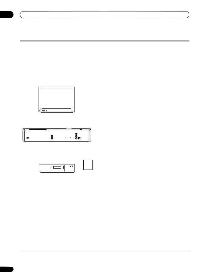
Easy connections
The setup described below is a basic setup that allows you to watch and record TV programs, and play discs. Other types of connections are explained starting on the following page.
 Important
•These connections use SCART cables (not supplied). If your TV (or VCR) does not have a SCART connection, see the following page for connecting up using the supplied audio/video cable.
•The AV1(RGB)-TV AV connector can output ordinary (composite), S-video or RGB video, plus stereo analog audio. The AV2(INPUT 1/DECODER) connector accepts ordinary, S-video and RGB video input, as well as stereo analog audio. See AV1 Out on page 112 and AV2/L1 In on page 113 for how to set them up.
•Before making or changing any rear panel connections, make sure that all components are switched off and unplugged from the wall outlet.
SCART AV |
|
|
|
|
|
ANTENNA |
|
|
CONNECTOR |
|
|
|
|
|
|
IN |
|
TV |
|
|
|
|
|
|
|
3 |
4 |
|
|
|
|
|
|
|
|
AV 2 (INPUT 1/DECODER) |
|
|
AV 1 (RGB) - TV |
|
|
ANTENNA |
||
|
|
|
|
|
|
COMPONENT |
|
IN |
|
|
|
|
|
|
VIDEO OUT |
|
|
|
|
|
|
|
|
Y |
|
|
COAXIAL |
|
|
|
|
IN PUT 3 |
|
|
|
AC IN |
|
|
|
|
|
PB |
|
|
|
|
|
|
|
|
|
|
|
|
|
|
|
|
|
PR |
G-LINK |
|
|
|
|
|
|
|
IN |
OUT |
|
OPTICAL |
HDMI OUT |
R |
AUDIO |
L |
VIDEO |
S-VIDEO |
CONTROL |
|
DIGITAL |
|
|
|
|
||||
AUDIO OUT |
|
|
|
|
OUT PUT |
|
|
|
5
2
SCART AV
CONNECTOR  ANTENNA
OUT
VCR |
ANTENNA |
|
IN |
1
Antenna/cable TV wall outlet
1Connect the cable from the antenna/cable TV outlet to the antenna input on your VCR.
•If you are not connecting a VCR in the chain, connect it to the ANTENNA IN jack on this recorder and skip the next step.
2Use an RF antenna cable (one is supplied) to connect the antenna output of your VCR to the ANTENNA IN of this recorder.
3Use another RF antenna cable to connect the ANTENNA OUT of this recorder to the antenna input on your TV.
4Use a SCART cable (not supplied) to connect the AV1(RGB)-TV AV connector on this recorder to the SCART AV connector on your TV.
5Use another SCART cable to connect the AV2(INPUT 1/DECODER) AV connector to a SCART AV connector on your VCR.
 Tip
Tip
•This recorder has a ‘through’ function which allows you to record a TV program from the built-in TV tuner in this recorder while watching a video playing on your VCR. (To use this feature when the recorder is in standby, Power Save must be set to Off—see Power Save on page 108).
14
En
Connecting up
Using other types of audio/video output
If you can’t use the SCART AV connector to connect your TV to this recorder, there are standard audio/video output jacks, as well as an S-video and component video output.
Using the supplied audio/video cable
AUDIO |
|
INPUT |
|
VIDEO |
|
INPUT |
|
TV |
|
2 |
1 |
AV 2 (INPUT 1/DECODER) |
AV 1 (RGB) - TV |
ANTENNA |
|
COMPONENT |
IN |
|
VIDEO OUT |
|
Y 
COAXIAL |
IN PUT 3 |
AC IN |
PB |
|
|
|
|
|
|
|
PR |
IN |
G-LINK |
|
|
|
|
|
|
OUT |
||
OPTICAL |
HDMI OUT |
R |
AUDIO |
L |
VIDEO |
S-VIDEO |
CONTROL |
|
DIGITAL |
|
|
|
|
OUT PUT |
|
|
|
AUDIO OUT |
|
|
|
|
|
|
|
1Connect the VIDEO OUTPUT jack to a video input on your TV.
Use the yellow jack of the supplied audio/video cable for the video connection.
2Connect the AUDIO OUTPUT jacks to the corresponding audio inputs on your TV.
Use the red and white jacks of the supplied audio/video cable for the audio connection. Make sure you match up the left and right outputs with their corresponding inputs for correct stereo sound.
Using the S-video or component video output
|
COMPONENT |
|
|
|
VIDEO INPUT |
|
|
|
AUDIO |
|
|
|
INPUT |
|
|
|
S-VIDEO |
|
|
2 |
INPUT |
1 |
|
TV |
|||
|
|
AV 2 (INPUT 1/DECODER) |
AV 1 (RGB) - TV |
ANTENNA |
|
|
|
|
COMPONENT |
IN |
|
VIDEO OUT |
|
Y
COAXIAL IN PUT 3
AC IN |
|
|
|
|
|
PB |
|
|
|
|
|
|
|
|
|
|
|
|
|
|
|
|
|
PR |
IN |
G-LINK |
|
|
|
|
|
|
OUT |
||
OPTICAL |
HDMI OUT |
R |
AUDIO |
L |
VIDEO |
S-VIDEO |
CONTROL |
|
DIGITAL |
|
|
|
|
OUT PUT |
|
|
|
AUDIO OUT |
|
|
|
|
|
|
|
1 Connect the S-video or component video output to a similar input on your TV.
For an S-video connection, use an S-video cable (not supplied) to connect the S-VIDEO OUTPUT jack to an S- video input on your TV
For a component video connection, use a component video cable (not supplied) to connect the COMPONENT VIDEO OUT jacks to a component video input on your TV.
See also Component Video Out on page 112 for how to set up the component video output for use with a progressive scan-compatible TV.
2 Connect the AUDIO OUTPUT jacks to the corresponding audio inputs on your TV.
You can use the supplied audio/video cable, leaving the yellow video plug disconnected. Make sure you match up the left and right outputs with their corresponding inputs for correct stereo sound.
02
English
15
En

02 Connecting up
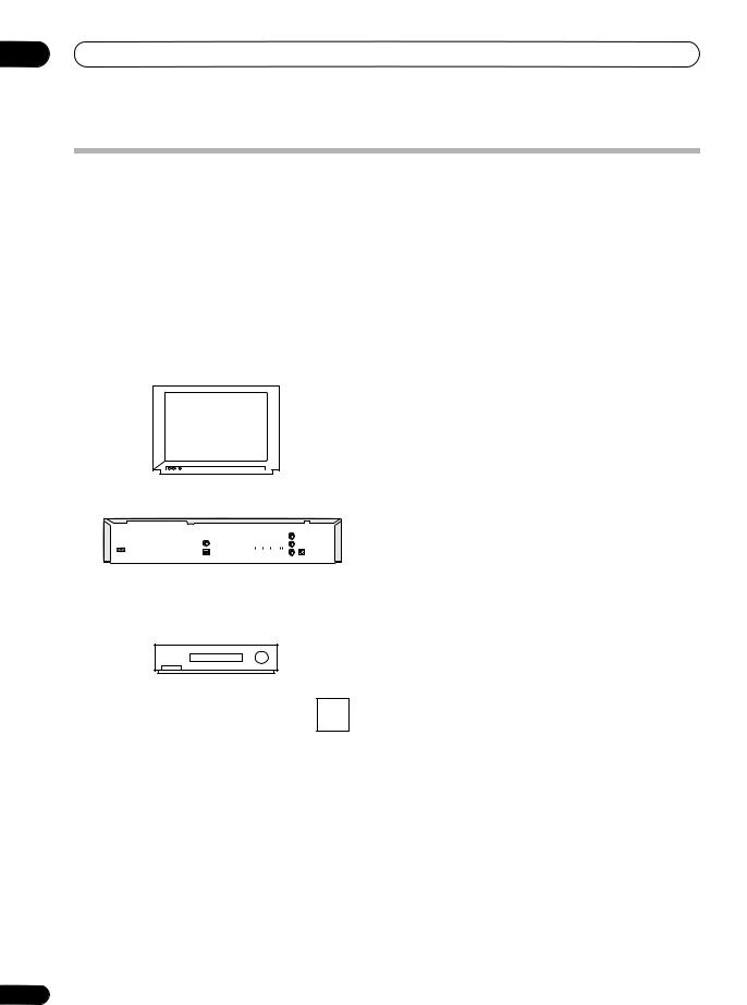
Connecting to a cable box, satellite receiver or digital terrestrial receiver
If you have a cable, satellite or digital terrestrial receiver with a built-in decoder, connect it to this recorder and your TV
as shown on this page.1 If you are using a separate decoder box for your cable/satellite TV, set up following the instructions on the next page.
Using the setup on this page you can:
•Record any channel by selecting it on the cable box, satellite receiver or digital terrestrial receiver.
•Change channels and set timer recordings on the external receiver using the GUIDE Plus+ system (via the G-LINK cable, and after setting up).
 Important
•Do not connect this recorder to your TV ‘through’ your VCR, satellite receiver or other component. Always connect each component directly to your TV or AV amplifier/receiver.
SCART AV |
|
CONNECTOR |
ANTENNA |
|
|
|
IN |
2 |
TV |
1
AV 2 (INPUT 1/DECODER) |
AV 1 (RGB) - TV |
ANTENNA |
|
COMPONENT |
IN |
|
VIDEO OUT |
|
|
|
|
|
|
IN PUT 3 |
Y |
|
|
COAXIAL |
|
|
|
|
|
|
|
|
AC IN |
|
|
|
|
|
PB |
|
|
|
|
|
|
|
|
|
|
|
|
|
|
|
|
|
PR |
IN |
G-LINK |
|
|
|
|
|
|
OUT |
||
OPTICAL |
HDMI OUT |
R |
AUDIO |
L |
VIDEO |
S-VIDEO |
CONTROL |
|
DIGITAL |
|
|
|
|
||||
AUDIO OUT |
|
|
|
|
OUT PUT |
|
|
|
3 |
|
4 |
1 |
|
SCART AV |
ANTENNA |
|
CONNECTOR |
||
OUT |
||
|
Cable/Satellite/ |
ANTENNA |
|
Digital Terrestrial |
IN |
|
receiver |
|
Satellite dish/ |
|
|
|
|
1 |
antenna/cable TV |
|
wall outlet |
1 Connect RF antenna cables as shown.
This enables you to watch and record TV channels.
2Use a SCART cable (not supplied) to connect the AV1(RGB)-TV AV connector to a SCART AV connector on your TV.
This enables you to watch discs.
3Use another SCART cable to connect the AV2(INPUT 1/DECODER) AV connector to a SCART AV connector on your cable box/satellite/digital terrestrial receiver.
This enables you to record scrambled TV channels.
4 Plug the supplied G-LINK cable to the G-LINK jack.
This enables you to control the tuner in the external receiver through GUIDE Plus+.
Position the IR transmitter end of the G-LINK cable so that the IR receiver on your cable/satellite/digital terrestrial receiver will pick up the control signals (see diagram).
AV 1 (RGB) - TV |
|
|
ANTENNA |
|
|
|
COMPONENT |
|
IN |
|
|
VIDEO OUT |
|
|
|
IN PUT 3 |
Y |
|
|
|
|
|
|
|
|
|
PB |
|
|
|
|
PR |
IN |
G-LINK |
|
|
OUT |
||
R AUDIO L |
VIDEO |
S-VIDEO |
CONTROL |
|
|
OUT PUT |
|
|
|
G-LINK cable
See the manual that came with your cable/satellite/ digital terrestrial receiver if you’re not sure where the IR receiver is on the front panel. Alternatively, experiment with the remote control, operating it from very close range until you find the place where the receiver responds.
 Tip
Tip
•This recorder has a ‘through’ function which allows you to record a TV program from the built-in TV tuner in this recorder while watching a video playing on your VCR. (To use this feature when the recorder is in standby, Power Save must be set to Off—see Power Save on page 108).
 Note
Note
1 The diagram shows SCART video connections, but you can alternatively use any of the other audio/video connections.
16
En
Connecting up
Connecting an external decoder box (1)
If you have an external, dedicated decoder box for your satellite or cable TV system, use the setup described on this page.
 Important
•Do not connect your decoder box directly to this recorder.
•Information from the decoder (for example, relating to pay TV services), is only viewable when this recorder is off (in standby).
•For timer recording to work properly on this recorder, the VCR/satellite receiver/cable box must also be switched on during recording.
•It is not possible to watch one TV program and record another using this setup.
SCART AV |
|
CONNECTOR |
|
4 |
TV |
AV 2 (INPUT 1/DECODER) |
AV 1 (RGB) - TV |
ANTENNA |
|
COMPONENT |
IN |
|
VIDEO OUT |
|
Y 
COAXIAL |
IN PUT 3 |
AC IN |
PB |
|
|
|
|
|
|
|
PR |
IN |
G-LINK |
|
|
|
|
|
|
OUT |
||
OPTICAL |
HDMI OUT |
R |
AUDIO |
L |
VIDEO |
S-VIDEO |
CONTROL |
|
DIGITAL |
|
|
|
|
OUT PUT |
|
|
|
AUDIO OUT |
|
|
|
|
|
|
|
|
3 |
|
|
2 |
|
SCART AV |
SCART AV |
|
CONNECTOR |
CONNECTOR |
|
Decoder |
VCR/Satellite receiver |
ANTENNA |
|
/Cable box |
|
|
IN |
|
|
|
 1
1
Antenna/cable TV wall outlet
02
English
1Connect the cable from the antenna/cable TV outlet to the antenna input on your VCR/satellite receiver/cable box.
2Use a SCART cable (not supplied) to connect your decoder to your VCR/satellite receiver/cable box.
See the manual for your decoder box for more detailed instructions.
3Use a SCART cable to connect your VCR/satellite receiver/cable box to the AV2(INPUT 1/DECODER) AV connector on this recorder.
4Use a SCART cable to connect the AV1(RGB)-TV AV connector to your TV.
17
En
02 Connecting up
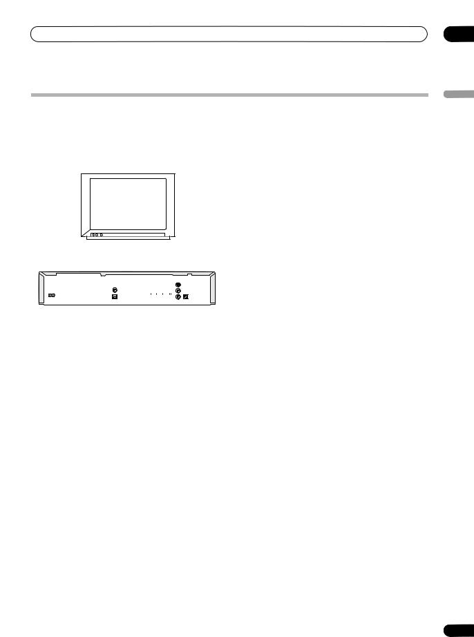
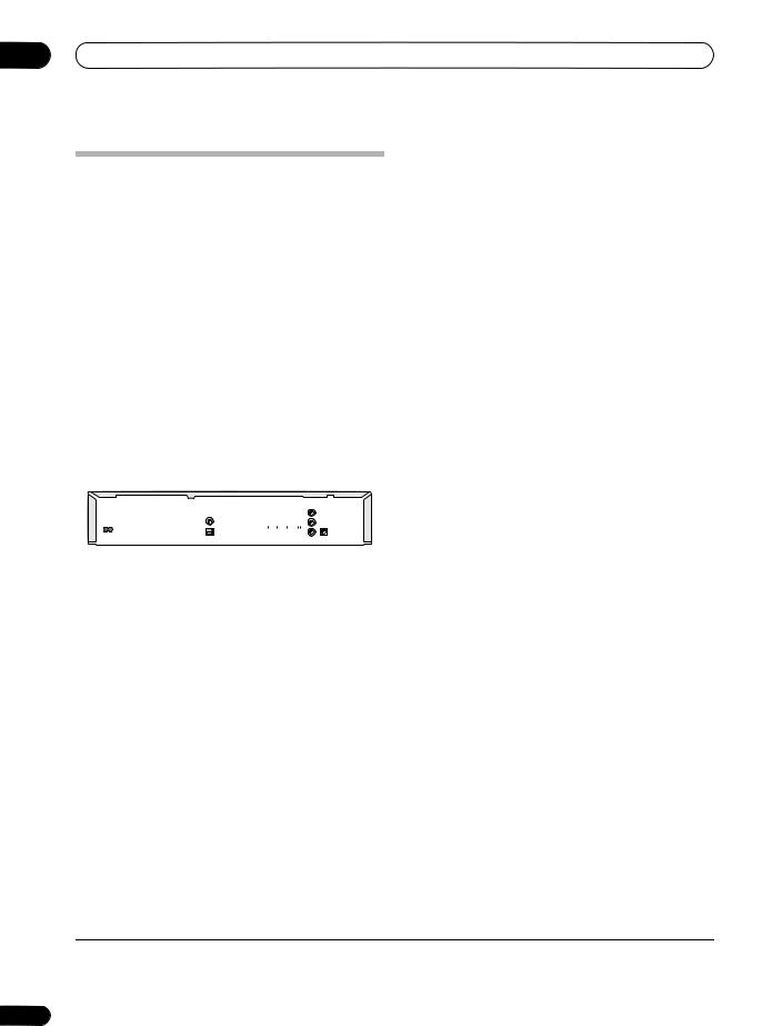
Connecting an external decoder box (2)
If you only have a decoder, connect it to this recorder and your TV as shown on this page.1
Using the setup on this page you can:
• Record scrambled channels received using the recorder’s built-in TV tuner.
 Important
•Do not connect this recorder ‘through’ your VCR, satellite receiver or cable box. Always connect each component directly to your TV or AV amplifier/receiver.
SCART AV |
|
CONNECTOR |
ANTENNA |
|
|
|
IN |
2 |
TV |
1
AV 2 (INPUT 1/DECODER) |
AV 1 (RGB) - TV |
ANTENNA |
|
COMPONENT |
IN |
|
VIDEO OUT |
|
Y 
COAXIAL |
IN PUT 3 |
AC IN |
PB |
|
|
|
|
|
|
|
PR |
IN |
G-LINK |
|
|
|
|
|
|
OUT |
||
OPTICAL |
HDMI OUT |
R |
AUDIO |
L |
VIDEO |
S-VIDEO |
CONTROL |
|
DIGITAL |
|
|
|
|
||||
AUDIO OUT |
|
|
|
|
OUT PUT |
|
|
|
3  1
1
SCART AV
CONNECTOR
|
Antenna/cable TV |
Decoder |
wall outlet |
1 Connect RF antenna cables as shown.
This enables you to watch and record TV channels.
2Use a SCART cable (not supplied) to connect the AV1(RGB)-TV AV connector to a SCART AV connector on your TV.
This enables you to watch discs.
3Use another SCART cable to connect the AV2(INPUT 1/DECODER) AV connector to a SCART AV connector on your decoder box.
This enables you to record scrambled TV channels.
 Note
Note
1 In order to use this setup, you will need to make the following settings from the Initial Setup menu:
•Set the AV2/L1 In setting to Decoder from the Initial Setup menu (see AV2/L1 In on page 113).
•From the Manual CH Setting screen, set the Decoder setting for the scrambled channels to On (see Manual CH Setting on page 110).
18
En
Connecting up
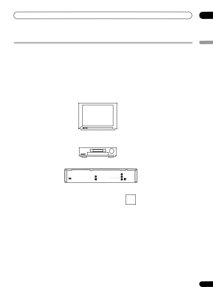
Connecting to an AV amplifier/receiver
To enjoy multichannel surround sound you need to connect this recorder to an AV amplifier/receiver using the digital optical output.
In addition to a digital connection, we recommend also connecting using the stereo analog connection for compatibility with all discs and sources.
You’ll probably also want to connect a video output to your AV amplifier/receiver. Use the ordinary video output (as shown here), or the S-video output.
 Important
•Noise may be output from your speakers if the recorder is not set up to work with your AV amplifier/receiver properly (see Audio Out settings on page 114).
ANTENNA
IN
VIDEO
IN
TV
4 
|
A/V |
VIDEO |
|
|
|
DIGITAL |
1 |
|
|
IN 1 |
OUT |
|
|
|
|
||
|
|
|
|
IN |
|
|
||
|
|
|
|
|
|
|
|
|
3 |
AV amp/ |
|
|
|
|
|
|
2 |
receiver |
|
|
|
|
|
|
|
|
|
AV 2 (INPUT 1/DECODER) |
|
|
AV 1 (RGB) - TV |
|
ANTENNA |
||
|
|
|
|
|
|
|
|
|
|
|
|
|
|
|
COMPONENT |
|
IN |
|
|
|
|
|
|
VIDEO OUT |
|
|
|
|
|
|
|
|
Y |
|
|
|
COAXIAL |
|
|
|
|
IN PUT 3 |
|
|
|
AC IN |
|
|
|
|
PB |
|
|
|
|
|
|
|
|
|
|
|
|
|
|
|
|
|
PR |
IN |
G-LINK |
|
|
|
|
|
|
OUT |
||
|
OPTICAL |
HDMI OUT |
R |
AUDIO |
L |
VIDEO S-VIDEO |
CONTROL |
|
|
DIGITAL |
|
|
|
|
|||
|
AUDIO OUT |
|
|
|
|
OUT PUT |
|
|
1 Connect RF antenna cables as shown.
This enables you to watch and record TV channels.
2Connect one of the DIGITAL OUT OPTICAL jack on this recorder to an optical digital input on your AV amplifier/receiver.
This enables you to listen to multichannel surround sound.
3Connect the analog AUDIO OUTPUT and VIDEO OUTPUT jacks on this recorder to an analog audio and video input on your AV amplifier/receiver.
4Connect the AV amplifier/receiver’s video output to a video input on your TV.
1
Antenna/cable TV wall outlet
 Important
•Do not connect this recorder to your TV ‘through’ your VCR using A/V cables. Always connect it directly to your TV.
02
English
19
En
02 Connecting up
Connecting using HDMI
If you have a HDMI or DVI-equipped1 monitor or display2, you can connect it to this recorder using an HDMI cable (not supplied).
The HDMI connector outputs uncompressed digital video, as well as almost every kind of digital audio.
1 Use an HDMI cable to connect the HDMI OUT connector on this recorder to an HDMI connector on an HDMI-compatible monitor.
HDMI
IN
HDMI-compatible display
AV 2 (INPUT 1/DECODER) |
AV 1 (RGB) - TV |
ANTENNA |
|
|
|
|
COMPONENT |
IN |
|
VIDEO OUT |
|
|
Y |
COAXIAL |
IN PUT 3 |
AC IN |
P |
|
|
|
OUT |
OPTICAL |
HDMI OUT |
DIGITAL |
|
AUDIO OUT |
|
•The arrow on the cable connector body should be face up for correct alignment with the connector on the recorder.
When connected to an HDMI component, HDMI 576P (PAL) or HDMI 480P (NTSC) is shown in the front panel display and the HDMI indicator lights.
HDMI setup is generally automatic. There are however settings you can change if you need to. See HDMI Output on page 121 for more information. Note that the HDMI settings remain in effect until you change them, or connect a new HDMI component.
 Important
•An HDMI connection can only be made with DVIequipped components compatible with both DVI and High-bandwidth Digital Content Protection (HDCP). If you choose to connect to a DVI connector, you wil need a DVI to HDMI adaptor cable. A DVI to HDCP connection, however, does not support audio. Consult your local audio dealer for more information.
•When connected to an HDCP-compatible DVI component, DVI 576P (PAL) or DVI 480P (NTSC) is displayed and the HDMI indicator lights.
•The HDMI connection is compatible with 44.1/48kHz, 16/20/24 bit 2-channel linear PCM signals, as well as Dolby Digital, DTS and MPEG audio bitstream.
About HDMI
HDMI (High Definition Multimedia Interface) supports both video and audio on a single digital connection for use with DVD players and recorders, DTV, set-top boxes, and other AV devices. HDMI was developed to provide the technologies of High Bandwidth Digital Content Protection (HDCP) as well as Digital Visual Interface (DVI) in one specification. HDCP is used to protect digital content transmitted and received by DVI-compliant displays.
HDMI has the capability to support standard, enhanced, or high-definition video plus standard to multi-channel surround-sound audio. HDMI features include uncompressed digital video, a bandwidth of up to 5 gigabits per second (Dual Link), one connector (instead of several cables and connectors), and communication between the AV source and AV devices such as DTVs.
HDMI, the HDMI logo and High-Definition Multimedia Interface are trademarks or registered trademarks of HDMI licensing LLC.
 Note
Note
1The resolution of this recorder’s HDMI video output is 576 x 480 pixels (PAL) or 480 x 720 pixels (NTSC) progressive. If your display is not compatible with these resolutions the picture may not be correctly reproduced.
2This unit has been designed to be compliant with HDMI (High Definition Multimedia Interface) version 1.1. Depending on the component you have connected, using a DVI connection may result in unreliable signal transfers.
20
En
Connecting up |
02 |
Connecting other AV sources
Connecting a VCR or analog camcorder
AUDIO/VIDEO |
AUDIO/VIDEO |
OUTPUT |
INPUT |
1 2
Connecting a DV camcorder
Using the front panel DV IN/OUT jack, it is possible to connect a DV camcorder or video deck, or DVD-R/RW recorder and digitally transfer DV tapes or DVD-R/RW discs to DVD-R/RW.
 Important
•This jack is for connection to DV equipment only. It is not compatible with digital satellite tuners or D-VHS video decks.
|
Analog camcorder |
AUDIO/VIDEO |
AUDIO/VIDEO |
INPUT |
OUTPUT |
|
VCR |
1Connect a set of audio and video outputs on your VCR or camcorder to a set of inputs on this recorder.
This enables you to record tapes from your VCR or camcorder.
•You can use ordinary video or S-video cables for the video connection.
•The front panel connections make convenient connections for a camcorder.
2Connect a set of audio and video inputs on your VCR or camcorder to a set of outputs on this recorder.
This enables you to record from this recorder to your VCR or camcorder.
•You can use ordinary video or S-video cables for the video connection.
•Alternatively, you can use the AV2(INPUT 1/ DECODER) SCART connector for audio/video input and output with just one SCART cable.
DV |
IN/OUT |
DV
IN/OUT
DV camcorder
1 Use a DV cable (not supplied) to connect the DV in/out jack on your DV camcorder/deck to the front panel DV IN/OUT jack of this recorder.
Plugging in
Before plugging in for the first time, make sure that everything is connected properly.
AC IN
1 Plug the supplied AC power cable into the AC IN inlet and the other end into a standard household power outlet.
English
21
En

03 Controls and displays
Chapter 3
Controls and displays
Front panel
1 |
2 |
3 |
4 |
5 |
6 |
7 |
8 |
9 |
10 |
11 |
|
|
|
|
|
DVD RECORDER DVR-920H |
|
|
|
OPEN/CLOSE |
|
ONE TOUCH |
HDD |
DVD |
STB CONTROL |
HDMI |
STOP REC |
COPY |
STANDBY / ON |
|
|
REC |
PULL |
|
|
|
|
OPEN |
12 |
13 |
14 |
|
15 |
Controls hidden behind the front panel door |
|
16 |
17 |
|
STANDBY / ON |
|
|
|
|
|
|
|
DISC |
INPUT |
REC |
S-VIDEO |
VIDEO |
AUDIO |
|
DV |
|
|
NAVIGATOR |
SELECT |
||
|
|
L(MONO) |
R |
IN / OUT |
|
|
|
|
|
|
|
|
|
|
|
|
|
ENTER |
RETURN |
REC MODE |
|
|
|
|
|
|
|
|
|
|
||
|
|
INPUT 2 |
|
|
|
|
|
|
|
|
|
|
18 |
|
|
19 |
20 |
|
21 |
22 |
|
1 HDD
Press to switch to the hard disk drive (HDD) for recording and playback. The button lights when HDD is selected.
2 DVD
Press to switch to DVD for recording and playback. The button lights when DVD is selected.
3 STB CONTROL indicator
Lights when this recorder is controlling an external receiver via the G-LINK cable during timer recording.
4 HDMI indicator
Lights when this recorder is connected to another HDMI/ DVI (HDCP) compatible component.
5Disc tray
6OPEN/CLOSE
Press to open/close the disc tray.
7
Press to stop playback.
8
Press to start or restart playback.
9 STOP REC
Press to stop recording.
10 ONE TOUCH COPY (page 72)
Press to start One Touch Copy of the currently playing title to DVD or the HDD.
11 +/– (page 33, 35, 63)
Use to change TV channels, skip chapters/tracks, etc.
12 STANDBY/ON
Press to switch the recorder on/into standby. The upperhalf of the button is backlit blue when the recorder is on.
13 Front panel display
See Display on page 23 for details.
14IR remote sensor (page 8)
15REC
Press to start recording. The upper-half of the button is backlit red when recording; the lower-half is backlit orange (blinking) when real-time copying.
16DISC NAVIGATOR (page 51, 86) Press to display the Disc Navigator screen.
17INPUT SELECT (page 67)
Press to change the input to use for recording.
22
En

Controls and displays |
03 |
18 Front panel inputs (page 12)
Pull the cover down where indicated to access the front panel input jacks. Especially convenient for connecting camcorders and other portable equipment.
19DV IN/OUT jack (page 12, 21, 67, 68, 69, 114, 129) Digital input/output jack for use with a DV camcorder.
20/ / / (cursor buttons) and ENTER
Used to navigate all on-screen displays. Press ENTER to select the currently highlighted option.
21 RETURN
Press to go back one level in the on-screen menu or display.
22 REC MODE (page 61)
Press repeatedly to change the recording mode (picture quality).
Display
1 |
2 |
3 |
4 |
5 |
6 |
7 |
8 |
9 |
10 |
11 |
|
|
||||||||||||||||||||
|
|
|
|
|
|
|
|
|
|
|
|
|
|
|
|
|
|
|
|
|
|
|
|
|
|
|
|
|
|
|
|
|
|
|
|
|
|
|
|
|
|
|
|
|
|
|
|
|
|
|
|
|
|
|
|
|
|
|
|
|
|
|
|
|
|
|
|
|
|
|
|
|
|
|
|
|
|
|
|
|
|
|
|
|
|
|
|
|
|
|
|
|
|
|
|
|
|
|
|
|
|
|
|
|
|
|
|
|
|
|
|
|
|
|
|
|
|
|
|
|
|
|
|
|
|
|
|
|
|
|
|
|
|
|
|
|
|
|
|
|
|
|
|
|
|
|
|
|
|
|
|
|
|
|
|
|
|
|
|
|
|
|
|
|
|
|
|
|
|
|
|
|
|
|
|
|
|
|
|
|
|
|
|
|
|
|
|
|
|
|
|
|
|
|
|
|
|
|
|
|
|
|
|
|
|
|
|
|
|
|
|
|
|
|
|
|
|
|
|
|
|
|
|
|
|
|
|
|
|
|
|
|
|
|
|
|
|
|
|
|
|
|
|
|
|
|
|
|
|
|
|
|
|
|
|
|
|
|
|
|
|
|
|
English
12 |
13 14 15 |
16 |
1 /
Arrows indicate the copy direction between the HDD (  ) and DVD (
  ).
).
2 PLAY / REC indicators
Lights during playback / recording; blinks when playback / recording is paused.
3 |
|
|
|
|
(page 31) |
The |
‘ |
’ |
and ‘ |
’ |
indicators light to indicate that the HDD |
or DVD is selected for recording/playback.
4 PL (page 86, 94)
Lights when a VR mode disc is loaded and the recorder is in Play List mode.
5 2 3 (page 109)
Shows the remote control mode (if nothing is displayed, the remote control mode is 1).
6 REM
Lights when the character display is showing the remaining available recording time.
7  (page 112)
Lights when the component video output is set to progressive scan.
8 V
Lights when an unfinalized Video mode disc is loaded.
9 R / RW
Indicates the type of recordable DVD loaded: DVD-R or DVD-RW.
10  (page 63)
Lights when a timer recording has been set. (Indicator blinks if the timer has been set to DVD but there isn’t a recordable disc loaded, or the timer has been set to HDD but the HDD is not recordable.)
11 Recording quality indicators (page 60)
When no indicator is lit, recording quality is set to SLP, otherwise the indicator shows the current setting:
FINE
Lights when the recording mode is set to FINE (best quality).
SP
Lights when the recording mode is set to SP (standard play).
LP
Lights when the recording mode is set to LP (long play).
EP
Lights when the recording mode is set to EP (extended play).
MN
Lights when the recording mode is set to MN (manual recording level) mode.
23
En
03 Controls and displays
12Character display
13
 (page 114)
Indicates which channels of a bilingual broadcast are recorded.
14VPS / PDC (page 63)
Lights when receiving a VPS/PDC broadcast during a VPS/PDC-enabled timer recording.
15NTSC
Lights when playing NTSC format video.
16OVER (page 114)
Lights when the analog audio input level is too high.
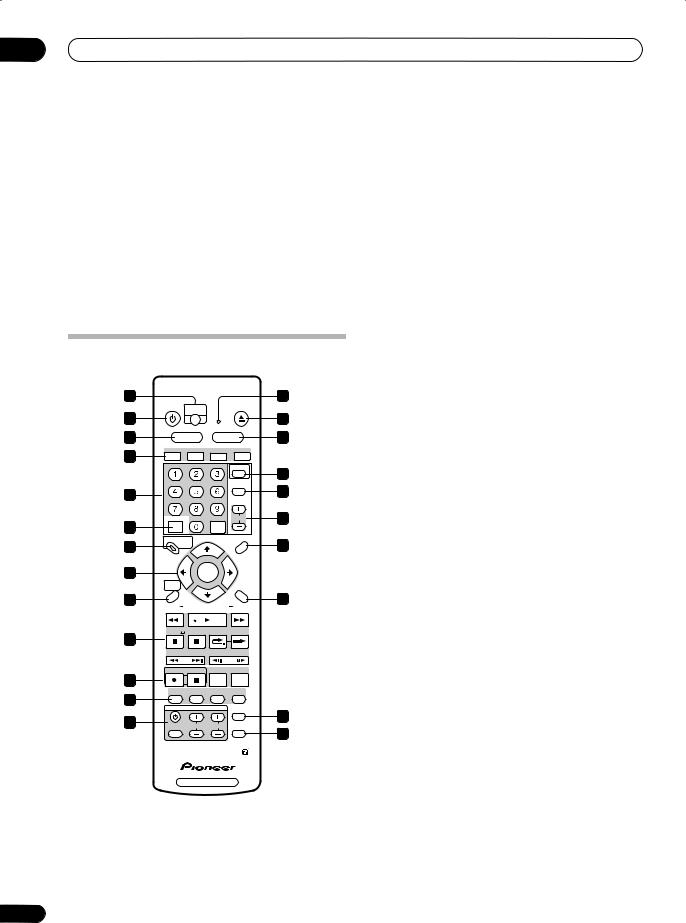
Remote control
1 |
|
|
|
|
|
2 |
|
|
STANDBY/ON |
ONETOUCH |
|
OPEN/CLOSE |
|
||
3 |
|
COPY |
|
|
|
4 |
|
|
|
|
|
|
|||
5 |
HDD |
DVD |
|
6 |
|||
7 |
AUDIO |
SUBTITLE |
ANGLE |
PLAY MODE |
|
||
|
|
|
|
|
|
||
|
|
ABC |
DEF |
|
GUIDE |
8 |
|
|
|
|
|
|
|||
|
|
|
|
|
INPUT |
||
|
GHI |
JKL |
MNO |
|
|
||
|
|
SELECT |
10 |
||||
|
|
|
|
|
|||
9 |
|
|
|
|
|
||
PQRS |
TUV |
WXYZ |
|
|
|
||
|
|
|
|
||||
12 |
+ |
|
CLEAR |
CHANNEL |
11 |
||
|
|
CLEAR |
|
|
|
||
13 |
DISC NAVIGATOR |
|
PLAY LIST |
14 |
|||
|
|
|
|
|
|||
|
TOP MENU |
|
|
|
MENU |
|
|
15 |
|
ENTER |
|
|
|
||
|
|
|
|
|
|||
|
HOME |
|
|
|
|
|
|
|
MENU |
|
|
|
RETURN |
|
|
16 |
|
|
|
|
|
17 |
|
|
REV SCAN |
PLAY |
FWD SCAN |
|
|||
18 |
PAUSE |
STOP OK |
BACK CM |
SKIP |
|
||
|
|
|
|
|
|
||
|
PREV SELECTIONCASE NEXT |
STEP / SLOW |
|
||||
|
REC |
STOP REC |
REC MODE |
TIMER REC |
|
||
19 |
|
|
|
|
|
|
|
|
NAVI |
CHP |
INFO |
DISPLAY |
|
||
20 |
MARK |
MARK |
|
||||
|
TV CONTROL |
|
|
|
|
||
|
|
|
TV / DVD |
21 |
|||
|
|
|
|
||||
22 |
INPUT |
CHANNEL |
VOLUME |
TV DIRECT |
|||
|
|||||||
|
SELECT |
|
|
|
REC |
23 |
|
|
|
|
|
|
|
||
DVD RECORDER
24
1 ONE TOUCH COPY (page 72)
Press to start One Touch Copy of the currently playing title to DVD or the HDD.
2 Remote control indicator
Lights when setting up the remote control for use with a TV (page 123) and when setting the remote control mode (page 109).
3 STANDBY/ON
Press to switch the recorder on/into standby.
4 OPEN/CLOSE
Press to open/close the disc tray.
5 HDD (page 31)
Press to select the hard disk (HDD) for recording or playback.
6 DVD (page 31)
Press to select the DVD for recording or playback.
7 GUIDE Plus+ Action buttons and DVD playback functions
When in the GUIDE Plus+ system, these buttons act as the Red, Green, Yellow and Blue Action buttons (the functions of these buttons change according to the GUIDE Plus+ Area. (page 40)
AUDIO (page 33, 58, 58)
Changes the audio language or channel. (When the recorder is stopped, press to change the tuner audio.)
SUBTITLE (page 58)
Displays/changes the subtitles included in multilingual DVD-Video discs.
ANGLE (page 59)
Switches camera angles on discs with multi-angle scenes.
PLAY MODE (page 55)
Press to display the Play Mode menu (for features such as search, repeat and program play).
8 GUIDE (page 40)
Press to display the GUIDE Plus+ screen.
9 Alphanumeric buttons and CLEAR
Use the number buttons for track/chapter/title selection; channel selection, and so on. The same buttons can also be used to enter names for titles, discs and so on.
Use CLEAR to clear an entry and start again.
10 INPUT SELECT (page 67)
Press to change the input to use for recording.
11 CHANNEL +/– (page 33)
Press to change the channel of the built-in TV tuner.
12 +
Use to input symbols when entering names for titles, discs and so on.
En

Controls and displays |
03 |
13DISC NAVIGATOR (page 51, 86) / TOP MENU
(page 35)
Press to display the Disc Navigator screen, or the top menu if a DVD-Video disc is loaded.
14PLAY LIST (page 86, 94) / MENU (page 35)
Press to switch between Original and Play List content on VR mode discs, or display the disc menu if a DVD-Video disc is loaded.
When in the GUIDE Plus+ system, use to jump directly to the Menu bar.
15 / / / (cursor buttons) and ENTER
Used to navigate all on-screen displays. Press ENTER to select the currently highlighted option.
16 HOME MENU (page 37)
Press to display the Home Menu, from which you can navigate all the functions of the recorder.
17 RETURN
Press to go back one level in the on-screen menu or display.
18 Playback controls (page 34) |
|
REV SCAN / FWD SCAN |
(page 53) |
Press to start reverse or forward scanning. Press again to change the speed.
PLAY
Press to start playback.
PAUSE
Press to pause playback or recording.
STOP
Press to stop playback.
CM BACK (commercial back)
Press repeatedly to skip progressively backward through the audio or video playing.
CM SKIP (commercial skip)
Press repeatedly to skip progressively forward through the audio or video playing.
PREV / NEXT
Press to skip to the previous or next title/chapter/ track/folder; or to display the previous or next menu page.
When in the GUIDE Plus+ system, use to display the previous/next page of TV listings information.
STEP/SLOW (page 54)
During playback, press to start slow-motion playback; while paused, press to show the previous or next video frame.
When in the GUIDE Plus+ system, use to display TV listings information for the previous/next day.
19 Recording controls (page 32)
REC
Press to start recording. Press repeatedly to set the recording time in blocks of 30 mins.
STOP REC
Press to stop recording.
REC MODE (page 61)
Press repeatedly to change the recording mode (picture quality).
TIMER REC (page 45)
Press to go directly to the Schedule area of the GUIDE Plus+ system.
20NAVI MARK (page 52)
Press to select a thumbnail picture for the current title for use in the Disc Navigator screen.
CHP MARK (page 91)
Press to insert a chapter marker when playing/ recording a VR mode DVD-RW disc or the HDD.
INFO (page 41)
Press to display additional TV program information in GUIDE Plus+.
DISPLAY (page 37)
Displays/changes the on-screen information displays.
21TV/DVD (page 33)
Press to switch between ‘TV mode’, in which you get the picture and sound from the TV’s tuner, and ‘DVD mode’, in which you get picture and sound from the recorder’s tuner (or an external input).
22 TV CONTROL (page 123)
After setting up, use these controls to control your TV.
23 TV DIRECT REC (page 63)
Press to start recording whatever channel your TV is set to.
English
25
En
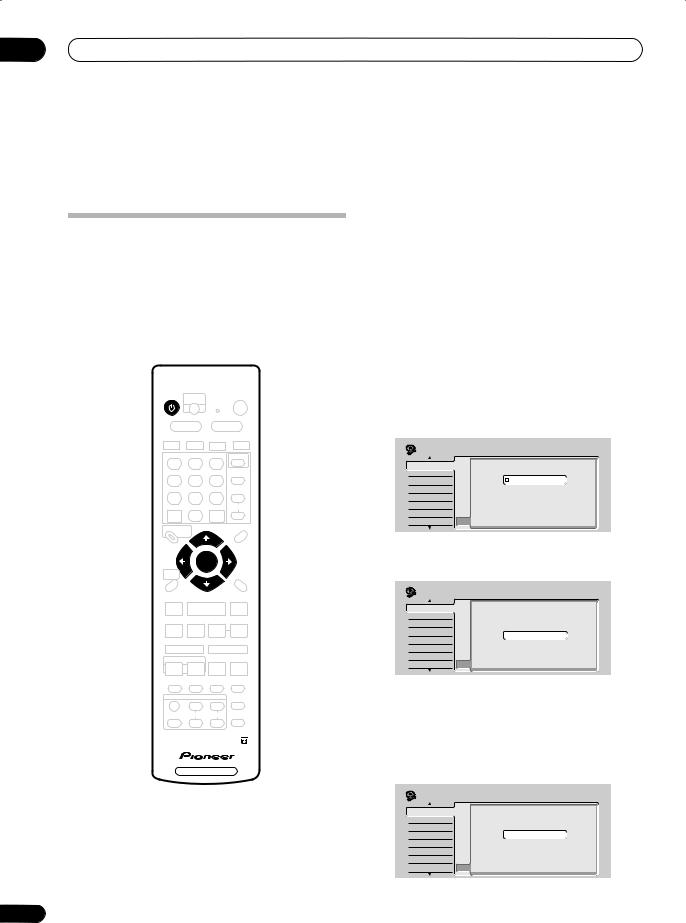
04 Getting started
Chapter 4
Getting started
Switching on and setting up
When you switch the recorder on for the first time, you can make several basic settings using the Setup Navigator feature. This takes you through setting the clock, the internal TV tuner and the video and audio output settings.
If you’re using the recorder for the first time, we strongly recommend you use the Setup Navigator before starting to use the recorder.
STANDBY/ON
ENTER
DVD RECORDER
26
1 Switch on your TV and set the video input to this recorder.
2 Press the STANDBY/ON button on the remote control or the front panel to switch on.
When you switch on for the first time, your TV should display the Setup Navigator screen. (If the Setup Navigator doesn’t appear, you can also access it from the Initial Setup menu; see page 109).
•If this recorder is connected to a compatible TV using a fully-wired 21-pin SCART cable, the recorder will take a few seconds to download country, TV screen size and language information. (Check the manual that came with your TV for compatibility information.)
3 Use the /(cursor up/down) buttons to choose a language, then press ENTER.
Initial Setup |
|
|
Basic |
Clock SetLanguage |
|
Tuner |
Input Line System |
English |
Video In/Out |
On Screen Display |
|
Audio In |
Front Panel Display français |
|
Audio Out |
Power Save |
Deutsch |
Language |
Remote Control SetItaliano |
|
Recording |
AV Link |
Español |
Playback |
Setup Navigator |
|
4 Press ENTER to start setting up using the Setup Navigator.
Initial Setup |
|
|
|
Basic |
Clock Set |
Complete this setup before you |
|
Tuner |
Input Line System |
||
Video In/Out |
|
start using your recorder. |
|
On Screen Display |
|||
Audio In |
Front Panel Display Start |
||
Audio Out |
Power Save |
||
Language |
Remote Control Set Cancel |
||
Recording |
AV Link |
Please use the Initial Setup if you |
|
want to make more detailed settings. |
|||
Playback |
|
||
Setup Navigator |
|||
•If you don’t want to use the Setup Navigator, press (cursor down) to select Cancel, then press ENTER to exit the Setup Navigator.
5 Select the Auto Channel Setting (‘Auto Scan’ or ‘Download from TV’), or ‘Do not set’, then press ENTER.
Initial Setup |
|
|
Basic |
Auto Channel Setting |
|
Clock Set |
|
|
Tuner |
Input Line System |
|
Video In/Out |
On Screen Display |
|
Audio In |
Front Panel Display Auto Scan |
|
Audio Out |
Power Save |
Download from TV |
Language |
Remote Control Set Do not set |
|
Recording |
AV Link |
|
Playback |
Setup Navigator |
|
En
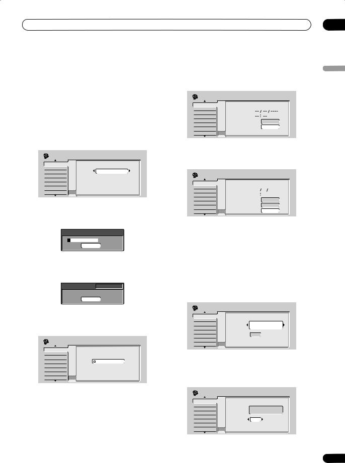
Getting started |
04 |
•Select Do not set if you want to skip setting up the channels (because they have already been set up, for example).
•You can only use the Download from TV feature if you connected this recorder to your TV using a fully-wired 21-pin SCART cable connected to the AV1(RGB)-TV connector, and if your TV supports this function (check your TV’s instruction manual for more details).
•Use the / (cursor left/right) buttons to choose your country, then press ENTER.
Initial Setup |
|
|
Basic |
Clock SetCountry Selection |
|
Tuner |
Input Line System |
UK |
Video In/Out |
Country |
|
On Screen Display |
|
|
Audio In |
Front Panel Display |
|
Audio Out |
Power Save |
|
Language |
Remote Control Set |
|
Recording |
AV Link |
|
Playback |
Setup Navigator |
|
•Auto-tuning channels
The Auto Scan option automatically scans and sets the channel presets.
Tuning
32/107
Cancel
•Downloading channels from your TV
Use the Download from TV option to download all the channels that your TV is tuned to.
Downloading |
Pr 5 |
|
Cancel |
6 Select ‘Auto’ for automatic time setting, or ‘Manual’ to set the clock manually, then press ENTER.
Initial Setup |
|
|
Basic |
Clock SetClock Setting |
|
Tuner |
Input Line System |
|
Video In/Out |
On Screen Display |
|
Audio In |
Front Panel Display Auto |
|
Audio Out |
Power Save |
Manual |
Language |
Remote Control Set |
|
Recording |
AV Link |
|
Playback |
Setup Navigator |
|
•Auto clock setting
Some TV channels broadcast time signals together with the program. This recorder can use these signals to set the clock automatically.
Set ‘Clock Set CH‘ to the channel preset number that broadcasts a time signal, then move the cursor down to ‘Start’ and press ENTER.
Initial Setup |
|
|
|
Basic |
Clock SetAuto Clock Setting |
|
|
Tuner |
Input Line System |
|
|
Video In/Out |
Date |
|
|
On Screen Display |
|
||
Audio In |
Time |
|
|
Front Panel Display |
|
||
Audio Out |
Power SaveClock Set CH |
Pr 1 |
|
Language |
Remote Control Set |
Start |
|
Recording |
AV Link |
||
|
|||
Playback |
Setup Navigator |
|
The recorder takes a short while to set the time. After you see that the time has been set, select Next to proceed.
Initial Setup |
|
|
|
|
Basic |
Clock SetAuto Clock Setting |
|
|
|
Tuner |
Input Line System |
THU |
01 |
01 2004 |
Video In/Out |
Date |
|||
On Screen Display |
|
11 |
20 |
|
Audio In |
Time |
|
||
Front Panel Display |
|
|
|
|
Audio Out |
Power SaveClock Set CH |
|
|
Pr 1 |
Language |
Remote Control Set |
|
|
Start |
Recording |
AV Link |
|
|
|
|
|
Next |
||
Playback |
Setup Navigator |
|
|
|
If the time could not be set automatically, press RETURN to go back to the previous screen and select
Manual.
•Manual clock setting
If no stations in your area are broadcasting time signals, you can set the clock manually.
Use the / (cursor left/right) buttons to set your time zone.
You can set this by selecting a city or a time relative to GMT.
Initial Setup |
|
|
|
Basic |
Clock SetManual Clock Setting |
1/2 |
|
Tuner |
Input Line System |
|
England |
Video In/Out |
On Screen Display |
|
|
Audio In |
Time Zone |
|
London |
Front Panel Display |
|
||
|
|
||
Audio Out |
Power Save |
Off |
|
Language |
Summer Time |
|
|
Remote Control Set |
|
|
|
Recording |
AV Link |
|
|
Playback |
Setup Navigator |
|
|
Press (cursor down) then use the / (cursor left/right) buttons to select ‘On’ or ‘Off’ for summer time, then press ENTER.
Select On if you are currently using summer time.
Initial Setup |
|
|
|
Basic |
Clock SetManual Clock Setting |
1/2 |
|
Tuner |
Input Line System |
|
England |
Video In/Out |
On Screen Display |
|
|
Audio In |
Time Zone |
|
London |
Front Panel Display |
|
||
|
|
||
Audio Out |
Power Save |
On |
|
Language |
Summer Time |
|
|
Remote Control Set |
|
|
|
Recording |
AV Link |
|
|
Playback |
Setup Navigator |
|
|
English
27
En
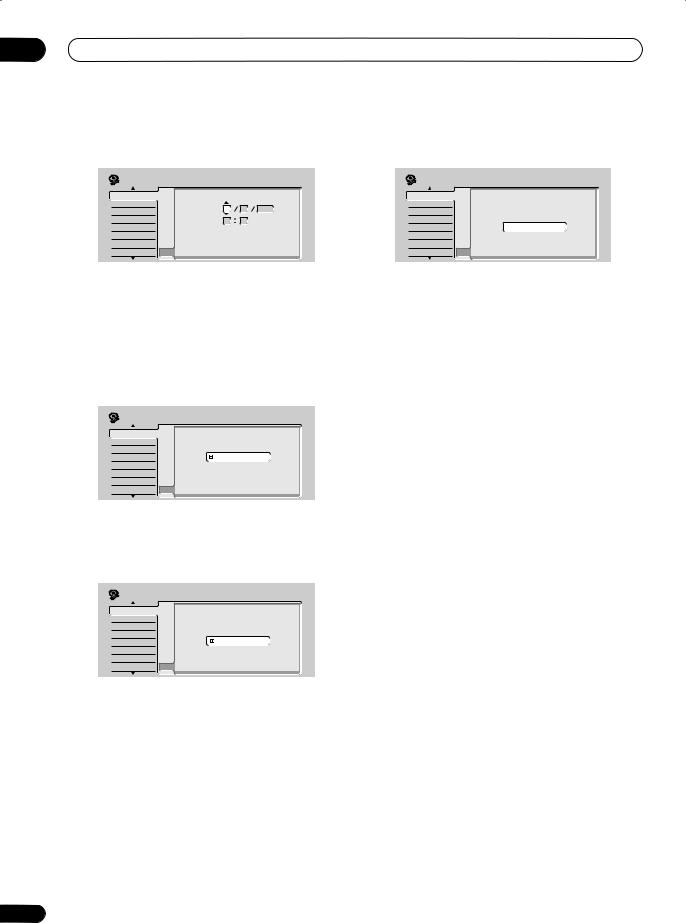
04 Getting started
Set the date (day/month/year) and time, then press ENTER to make all the settings.
Initial Setup |
|
|
|
|
|
Basic |
Clock SetManual Clock Setting |
|
2/2 |
||
Tuner |
Input Line System |
THU |
01 |
01 |
2004 |
Video In/Out |
Date |
||||
On Screen Display |
|
|
|
|
|
Audio In |
Front PanelTime Display |
00 |
00 |
|
|
Audio Out |
Power Save |
|
Austria |
|
|
Language |
Time Zone |
|
|
|
|
Remote Control Set |
Vienna |
|
|
||
Recording |
AV Link |
|
|
|
|
|
On |
|
|
||
Playback |
Summer Time |
|
|
||
Setup Navigator |
|
|
|
|
|
9 Press ENTER to exit the Setup Navigator, or select ‘Go Back’ if you want to start again.
Initial Setup |
|
|
Basic |
Clock Set |
|
Tuner |
Input Line System |
|
Video In/Out |
Setup is complete! |
|
On Screen Display |
|
|
Audio In |
Enjoy using your DVD recorder! |
|
Front Panel Display |
Finish Setup |
|
Audio Out |
Power Save |
|
Language |
Remote Control SetGo Back |
|
Recording |
AV Link |
|
Playback |
Setup Navigator |
|
Use the / (cursor up/down) buttons to change the value in the highlighted field.
Use the / (cursor left/right) buttons to move from one field to another.
•You can go back to the previous screen at anytime in the Setup Navigator by pressing RETURN.
7 Select the TV screen type, ‘Wide (16:9)’ or ‘Standard (4:3)’.
Initial Setup |
|
|
Basic |
Clock SetTV Screen Size |
|
Tuner |
Input Line System |
|
Video In/Out |
On Screen Display |
|
Audio In |
Front Panel Display Wide (16:9) |
|
Audio Out |
Power Save |
Standard (4:3) |
Language |
Remote Control Set |
|
Recording |
AV Link |
|
Playback |
Setup Navigator |
|
Use the / (cursor up/down) buttons to select, then press ENTER.
8 Is your TV compatible with progressive scan video?
Initial Setup |
|
|
Basic |
Clock SetProgressive |
|
Tuner |
Input Line System |
|
Video Out |
On Screen Display |
Compatible |
Audio In |
Front Panel Display |
|
Audio Out |
Power Save |
Not Compatible |
Language |
Remote Control Set Don't Know |
|
Recording |
AV Link |
|
Playback |
Setup Navigator |
|
Use the / (cursor up/down) buttons to select
Compatible, Not Compatible, or Don’t Know, then press ENTER.
•Note that progressive scan video is only output through the AV1(RGB)-TV connector and the component video outputs.
That completes basic setup using the Setup Navigator.
Other settings you can make
After setting up using the Setup Navigator, you should be ready to start enjoying your DVD recorder. It’s possible, however, that you may want to make a couple of additional settings, depending on how the recorder is set up for terrestrial TV broadcasts.
•Manual channel setting – This setting lets you skip channels where there is no station, as well as manually tune to stations. See Manual CH Setting on page 110.
•Setting up the remote to control your TV – You can set up the supplied remote control to control many brands of TV. See Setting up the remote to control your TV on page 123.
28
En
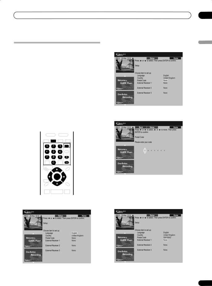
Getting started
Setting up the GUIDE Plus+ system
The GUIDE Plus+™ system is a free, interactive onscreen television programming guide. The system offers program listings for all major channels, one-touch recording, search by genre, recommendations according to your profile and more.
For GUIDE Plus+ to function correctly, it is important that you set the language and country correctly in the Setup Navigator, and that you have performed a scan for available channels, as these are all used by the GUIDE Plus+ system. If any of these things are not yet set, please run the Setup Navigator first (see Switching on and setting up on page 26).
TV listings information is received via ‘host channels’. In order to receive the correct TV listings information for your country or region you need to set up the GUIDE Plus+ system and ‘download’ the TV listings information. The initial download can take up to 24 hours, but once this is done, all future updates are automatic.
2 Use the / (cursor up/down) buttons to select
Postal Code.
3 Use the number and cursor buttons to enter your postal code.
04
English
GUIDE
CHANNEL
ENTER
1 Press GUIDE to display the GUIDE Plus+ setup menu.
The language and country settings are already set to whatever you selected in the Setup Navigator.
The system uses your postal code to identify which TV listings data is correct for the area in which you live, so it is important that you enter it correctly.
4 If you are using an external receiver (such as a satellite receiver) with the supplied G-LINK cable, complete this step, otherwise jump to step 5 below.
•See Connecting to a cable box, satellite receiver or digital terrestrial receiver on page 16 for more on using the supplied G LINK cable.
29
En

04 Getting started
•Select External Receiver 1, 2 or 3, then press ENTER. (If you have just one external receiver, use External Receiver 1. You can add further setups in 2 and 3 if you need to.)
After pressing ENTER:
•Select your reception method (Terrestrial, Cable or
Satellite).
•Select your provider (if applicable).
•Select the brand of your external receiver.
•Identify which input your external receiver is connected to.
After completing these steps the recorder will try and communicate with your external receiver and change the channel via the G-LINK cable. If the channel was successfully changed, select Yes to confirm.
If the channel did not change, select No. The GUIDE Plus+ system will try other codes assigned to your external receiver. If none of the codes changes the channel successfully, tune your external receiver to the host channel for your country (refer to step 5 below) and leave it on overnight. The recorder needs to be in standby. It will wake up automatically and download new codes from the host channel. The next day, try this setup process again:
•Press GUIDE to display the GUIDE Plus+ setup menu.
•Press (cursor up) to highlight the Menu bar, then use (cursor right) to reach the Setup area and select Setup.
•Continue setting up from the start of this step again.
If your external receiver still doesn’t respond to the G- LINK controller, please call customer support and report the brand and model of your external receiver.
See also GUIDE Plus+ FAQ and troubleshooting on page 49.
5 Identify the host channel for your country.
The TV listings information available in GUIDE Plus+ is distributed throughout Europe by selected broadcasters called host channels. It is important that the host channel for your country is correctly identified in order to receive listings information (EPG download).
A If you are not using an external receiver, this recorder will automatically scan all channels for the host channel:
•Leave the recorder in standby overnight (do not leave it switched on).
30
B If you are using an external receiver, you need to identify the host channel from the table below:
Country/ |
Host channels |
Comments |
|
Region |
|||
|
|
||
|
|
|
|
Austria |
Eurosport |
|
|
|
|
|
|
Belgium |
Music Factory (TMF) |
|
|
(Flemish) |
|
|
|
|
|
|
|
France |
Canal+ |
Analog only |
|
|
|
|
|
Germany |
Eurosport |
|
|
|
|
|
|
Italy |
Sport Italia |
Analog only |
|
|
|
|
|
Netherlands |
Music Factory (TMF), |
Use TMF if you live in |
|
|
Eurosport |
Amsterdam, Eindhoven or |
|
|
|
Rotterdam. |
|
|
|
|
|
Spain |
Tele 5 |
Analog only |
|
|
|
|
|
Switzerland |
Eurosport |
|
|
|
|
|
|
UK |
ITV, Eurosport |
ITV is analog only. Use |
|
|
|
Eurosport if you are a SKY |
|
|
|
subscriber and you no longer |
|
|
|
have a terrestrial antenna. |
|
|
|
|
•Tune your external receiver to the appropriate host channel and leave the receiver on and the recorder in standby overnight.
C If you use both an external receiver and this recorder as sources, follow the instructions above for setting up without an external receiver. Only if this is unsuccessful try the external receiver method.
About EPG download
•EPG data can only be received when the recorder is in standby. (When not using the recorder, therefore, please switch it into standby.) If you’re using an external receiver, leave this on when EPG data is downloadng.
•If you cannot receive any of the host channels (see the above table) then you won’t be able to use the GUIDE Plus+ system. In this case do not set the postal code in the GUIDE Plus+ setup screen. (When GUIDE Plus+ service starts in your area, set the postal code again.)
•Even if you can’t use the EPG functions where you live, you can still set VIDEO Plus+ timer recordings and manual recordings — see page 47.
•The front panel display shows EPG when receiving data. If you power on the recorder during an EPG download, the download is canceled.
•EPG data may be received several times a day. All updates are automatic.
•When downloading EPG data, the recorder may sound as though it is on. This is normal.
En
 Loading...