


 Loading...
ORDER NO.
RRV3271
DV-989AVi-S
DVD PLAYER
DV-989AVi-S
DV-989AVi-G
THIS MANUAL IS APPLICABLE TO THE FOLLOWING MODEL(S) AND TYPE(S).
Model |
Type |
Power Requirement |
Region No. |
Remarks |
||||||
|
|
|
|
|
|
|
|
|
|
|
DV-989AVi-S |
WYXJ |
AC220–240V |
2 |
|
||||||
|
|
|
|
|
|
|
|
|
|
|
DV-989AVi-S |
YXJRE |
AC220–240V |
5 |
|
||||||
|
|
|
|
|
|
|
|
|
|
|
DV-989AVi-G |
HLXJ |
AC220-240V |
3 |
|
||||||
|
|
|
|
|
|
|
|
|
|
|
DV-989AVi-S |
WPWXJ |
AC220–240V |
4 |
|
||||||
|
|
|
|
|
|
|
|
|
|
|
|
|
|
|
|
|
|
|
|
|
|
|
|
|
|
|
|
|
|
|
|
|
|
|
|
|
|
|
|
|
|
|
|
|
|
|
|
|
|
|
|
|
|
|
|
|
|
|
|
|
|
|
|
|
|
For details, refer to "Important symbols for good services".
PIONEER CORPORATION 4-1, Meguro 1-chome, Meguro-ku, Tokyo 153-8654, Japan
PIONEER ELECTRONICS (USA) INC. P.O. Box 1760, Long Beach, CA 90801-1760, U.S.A.
PIONEER EUROPE NV Haven 1087, Keetberglaan 1, 9120 Melsele, Belgium
PIONEER ELECTRONICS ASIACENTRE PTE. LTD. 253 Alexandra Road, #04-01, Singapore 159936
 PIONEER CORPORATION 2005
T-ZZR OCT. 2005 printed in Japan

1 |
2 |
3 |
4 |
SAFETY INFORMATION
A
This service manual is intended for qualified service technicians ; it is not meant for the casual do-it yourselfer. Qualified technicians have the necessary test equipment and tools, and have been trained to properly and safely repair complex products such as those covered by this manual.
Improperly performed repairs can adversely affect the safety and reliability of the product and may void the warranty. If you are not qualified to perform the repair of this product properly and safely, you should not risk trying to do so and refer the repair to a qualified service technician.
WARNING !
THE AEL (ACCESSIBLE EMISSION LEVEL) OF THE LASER POWER OUTPUT IS LESS THAN CLASS 1 BUT THE LASER COMPONENT IS CAPABLE OF EMITTING RADIATION EXCEEDING
BTHE LIMIT FOR CLASS 1.
A SPECIALLY INSTRUCTED PERSON SHOULD DO SERVICING OPERATION OF THE APPARATUS.
LASER DIODE CHARACTERISTICS
FOR DVD : MAXIMUM OUTPUT POWER : 5 mW WAVELENGTH : 650 nm
FOR CD : MAXIMUM OUTPUT POWER : 5 mW WAVELENGTH : 780 nm
LABEL CHECK
C
Additional Laser Caution
1.Loading-status detection switch (S101 on the LOAB assy) are detected by the microprocessor (IC601 in the DVDM assy).
• To permit the laser diode to oscillate, it is required to set the loadingstatus detection switch for the clamp position (the center terminal of S101 is shorted to +3V).
When the voltage of IC101-pin 21 is +3V, IC601 (microprocessor) -pin 83 is +3V and IC601-pin 84 is +3V, 650nm laser diode for DVD oscillates in the DVDM Assy.
When the voltage of IC101-pin 21 is +3V, IC601 (microprocessor) -pin 83 is 0V (GND) and IC601-pin 84 is +3V, 780nm laser diode for CD oscillates in the DVDM Assy.
In the test mode * , the laser diode oscillates when microprocessor detects a PLAY signal, or when the PLAY key is pressed (S104 ON in the FLKY assy), with the above requirements satisfied.
2.When the cover is open, close viewing through the objective lens with the naked eye will cause exposure to the laser beam.
: See page 87.
D
(Printed on the Rear Panel)
E
F
2 |
|
DV-989AVi-S |
|
|
1 |
2 |
|
3 |
4 |

5 |
6 |
7 |
8 |
[Important Check Points for Good Servicing]
In this manual, procedures that must be performed during repairs are marked with the below symbol. Please be sure to confirm and follow these procedures.
1. Product safety
Please conform to product regulations (such as safety and radiation regulations), and maintain a safe servicing environment by following the safety instructions described in this manual.
1 Use specified parts for repair.
Use genuine parts. Be sure to use important parts for safety.
2 Do not perform modifications without proper instructions.
Please follow the specified safety methods when modification(addition/change of parts) is required due to interferences such as radio/TV interference and foreign noise.
3 Make sure the soldering of repaired locations is properly performed.
When you solder while repairing, please be sure that there are no cold solder and other debris.
Soldering should be finished with the proper quantity. (Refer to the example)
4 Make sure the screws are tightly fastened.
Please be sure that all screws are fastened, and that there are no loose screws.
5 Make sure each connectors are correctly inserted.
Please be sure that all connectors are inserted, and that there are no imperfect insertion.
6 Make sure the wiring cables are set to their original state.
Please replace the wiring and cables to the original state after repairs.
In addition, be sure that there are no pinched wires, etc.
7 Make sure screws and soldering scraps do not remain inside the product.
Please check that neither solder debris nor screws remain inside the product.
8 There should be no semi-broken wires, scratches, melting, etc. on the coating of the power cord.
Damaged power cords may lead to fire accidents, so please be sure that there are no damages.
If you find a damaged power cord, please exchange it with a suitable one.
9 There should be no spark traces or similar marks on the power plug.
When spark traces or similar marks are found on the power supply plug, please check the connection and advise on secure connections and suitable usage. Please exchange the power cord if necessary.
0 Safe environment should be secured during servicing.
When you perform repairs, please pay attention to static electricity, furniture, household articles, etc. in order to prevent injuries. Please pay attention to your surroundings and repair safely.
2. Adjustments
To keep the original performance of the products, optimum adjustments and confirmation of characteristics within specification. Adjustments should be performed in accordance with the procedures/instructions described in this manual.
3. Lubricants, Glues, and Replacement parts
Use grease and adhesives that are equal to the specified substance.


 Make sure the proper amount is applied.
4. Cleaning
For parts that require cleaning, such as optical pickups, tape deck heads, lenses and mirrors used in projection monitors, proper cleaning should be performed to restore their performances.
5. Shipping mode and Shipping screws
A
B
C
D
E
To protect products from damages or failures during transit, the shipping mode should be set or the shipping screws should be installed before shipment. Please be sure to follow this method especially if it is specified in this manual.
F
|
|
|
|
|
|
|
|
|
DV-989AVi-S |
7 |
3 |
||
5 |
6 |
|
|
|
8 |
|
1 2 3 4
CONTENTS
|
SAFETY INFORMATION ..................................................................................................................................... |
2 |
|
A |
1. SPECIFICATIONS ............................................................................................................................................ |
5 |
|
2. EXPLODED VIEWS AND PARTS LIST |
6 |
||
|
|||
|
2.1 PACKING ................................................................................................................................................... |
6 |
|
|
2.2 EXTERIOR SECTION................................................................................................................................ |
8 |
|
|
2.3 FRONT PANEL SECTION ....................................................................................................................... |
10 |
|
|
2.4 LOAD MECHA. ASSY.......................................................................................................................... |
12 |
|
|
2.5 TRAVERSE MECHA. ASSY-S ................................................................................................................. |
14 |
|
|
3. BLOCK DIAGRAM AND SCHEMATIC DIAGRAM .......................................................................................... |
16 |
|
|
3.1 OVERAL BLOCK DIAGRAM.................................................................................................................... |
16 |
|
|
3.2 LOAB ASSY and OVERALL WIRING DIAGRAM..................................................................................... |
18 |
|
|
3.3 DVDM ASSY 1/6 [FTS BLOCK] ............................................................................................................... |
20 |
|
|
3.4 DVDM ASSY 2/6 [FR BLOCK] ................................................................................................................. |
22 |
|
B |
3.5 DVDM ASSY 3/6 [EBY/AV1 BLOCK] ....................................................................................................... |
24 |
|
3.6 DVDM ASSY 4/6 [i.LINK BLOCK] |
26 |
||
|
|||
|
3.7 DVDM ASSY 5/6 [VIDEO BLOCK]........................................................................................................... |
28 |
|
|
3.8 DVDM ASSY 6/6 [A-DSP/AQE/SACD BLOCK]........................................................................................ |
30 |
|
|
3.9 AJKB ASSY ............................................................................................................................................. |
32 |
|
|
3.10 VJKB ASSY............................................................................................................................................ |
34 |
|
|
3.11 FLKY, KEYB and MSWB ASSYS........................................................................................................... |
36 |
|
|
3.12 SCRB ASSY (WYXJ5, YXJRE5 Only) ................................................................................................... |
38 |
|
|
3.13 POWER SUPPLY UNIT.......................................................................................................................... |
40 |
|
|
3.14 WAVEFORMS ........................................................................................................................................ |
42 |
|
|
4. PCB CONNECTION DIAGRAM ..................................................................................................................... |
45 |
|
|
4.1 LOAB ASSY ............................................................................................................................................. |
45 |
|
C |
4.2 DVDM ASSY ............................................................................................................................................ |
46 |
|
|
4.3 AJKB ASSY ............................................................................................................................................. |
50 |
|
|
4.4 VJKB ASSY.............................................................................................................................................. |
52 |
|
|
4.5 FLKY and KEYB ASSYS ......................................................................................................................... |
54 |
|
|
4.6 SCRB ASSY ............................................................................................................................................ |
58 |
|
|
4.7 PS ASSY.................................................................................................................................................. |
60 |
|
|
4.8 POWER SUPPLY UNIT............................................................................................................................ |
61 |
|
|
5. PCB PARTS LIST ........................................................................................................................................... |
62 |
|
|
6. ADJUSTMENT ............................................................................................................................................... |
86 |
|
|
6.1 ADJUSTMENT ITEMS AND LOCATION ................................................................................................. |
86 |
|
|
6.2 JIGS AND MEASURING INSTRUMENTS............................................................................................... |
86 |
|
|
6.3 NECESSARY ADJUSTMENT POINTS ................................................................................................... |
87 |
|
D |
6.4 TEST MODE ............................................................................................................................................ |
88 |
|
|
6.5 MECHANISM ADJUSTMENT .................................................................................................................. |
89 |
|
|
7. GENERAL INFORMATION ............................................................................................................................. |
91 |
|
|
7.1 DIAGNOSIS ............................................................................................................................................. |
91 |
|
|
7.1.1 ID NUMBER AND ID DATA SETTING ............................................................................................... |
91 |
|
|
7.1.2 SELF-DIAGNOSIS FUNCTION OF PICKUP DEFECTIVE ............................................................... |
93 |
|
|
7.1.3 TEST MODE SCREEN DISPLAY ...................................................................................................... |
94 |
|
|
7.1.4 SELF-DIAGNOSIS FUNCTION ......................................................................................................... |
96 |
|
|
7.1.5 FUNCTIONAL SPECIFICATION OF THE SERVICE MODE ............................................................. |
97 |
|
|
7.1.6 ERROR DISPLAY .............................................................................................................................. |
98 |
|
|
7.1.7 TROUBLE SHOOTING .................................................................................................................... |
101 |
|
|
7.1.8 FAILURE-TEST METHOD FOR THE HDMI TRANSMITTER IC ..................................................... |
103 |
|
E |
7.1.9 SERIAL-DOWNLOAD...................................................................................................................... |
104 |
|
|
7.1.10 DISASSEMBLY.............................................................................................................................. |
105 |
|
|
8. PANEL FACILITIES ...................................................................................................................................... |
115 |
F
4 |
|
DV-989AVi-S |
|
|
1 |
2 |
|
3 |
4 |
5 |
6 |
1. SPECIFICATIONS
Specifications
General
System. . . . . . . . . . . . . . . . . . . . . . . . .DVD Player Power requirements. . . . AC 220-240 V, 50/60 Hz Power consumption. . . . . . . . . . . . . . . . . . . 25 W Power consumption (standby) . . . . . . . . . . 0.3 W Weight. . . . . . . . . . . . . . . . . . . . . . . . . . . . . 9.0 kg Weight. . . . . . . . . . . . . . . . . (HLXJ model) 10.0 kg Dimensions. . . . 420 (W) x 117 (H) x 340 (D) mm Operating temperature. . . . . . . . +5°C to +35°C Operating humidity . . . . . . . . . . . . . . . 5% to 85%
(no condensation)
HDMI output
HDMI output . . . . . . . . . . . . . . . . . . . . . . . . 19 pin
i.LINK output
i.LINK output . . . . . . . . . . . . . . . . . . . 4 pin (S400)
Component Video output (Y, PB, PR)
Output level . . . . . . . . . . . . . . . .Y: 1.0 Vp-p (75 Ω) PB, PR: 0.7 Vp-p (75 Ω)
Jacks . . . . . . . . . . . . . . . . . . . . . . . . . . .RCA jacks
S-Video output
Y (luminance) - Output level . . . . . 1 Vp-p (75 Ω) C (color) - Output level. . . . . . . 286 mVp-p (75 Ω) Jack . . . . . . . . . . . . . . . . . . . . . . . . . . S-Video jack
Video output
Output level . . . . . . . . . . . . . . . . . . 1 Vp-p (75 Ω) Jack. . . . . . . . . . . . . . . . . . . . . . . . . . . . .RCA jack
AV connector output
AV Connector (21-pin connector assignment) AV connector output. . . . . . . . .21-pin connector This connector provides the video and audio signals for connection to a compatible color TV or monitor.
PIN no.
1 . . . . . . . . . . . . . . . . . . . . . . . . . . . Audio 2/R out 3 . . . . . . . . . . . . . . . . . . . . . . . . . . . .Audio 1/L out 4 . . . . . . . . . . . . . . . . . . . . . . . . . . . . . . . . . . .GND 7 . . . . . . . . . . . . . . . . . . . . . . . . . . . . . . . . . B* out 8 . . . . . . . . . . . . . . . . . . . . . . . . . . . . . . . . . Status 11 . . . . . . . . . . . . . . . . . . . . . . . . . . . . . . . . G* out 15 . . . . . . . . . . . . . . . . . . . . . . . . . . . R* or C* out 17. . . . . . . . . . . . . . . . . . . . . . . . . . . . . . . . . .GND 19 . . . . . . . . . . . . . . . . . . . . . .Video out or Y* out 21 . . . . . . . . . . . . . . . . . . . . . . . . . . . . . . . . . .GND *AV CONNECTOR 1 (RGB)-TV/AV Receiver is output
7 |
8 |
Audio output (1 stereo pair)
Output level . . . . . . . . . . . . .During audio output 200 mVrms (1 kHz, –20 dB)
Number of channels. . . . . . . . . . . . . . . . . . . . . .2 Jacks. . . . . . . . . . . . . . . . . . . . . . . . . . . RCA jack
Audio output (multi-channel / L, R, C, SW, LS, RS)
Output level . . . . . . . . . . . . . During audio output 200 mVrms (1 kHz, –20 dB)
Number of channels. . . . . . . . . . . . . . . . . . . . . .6 Jacks . . . . . . . . . . . . . . . . . . . . . . . . . . . RCA jack
Audio characteristics
Frequency response
. . . . . . . . . . . . . .4 Hz to 44 kHz(DVD fs: 96 kHz)
. . . . . . . 4 Hz to 88 kHz (DVD-Audio fs: 192 kHz) S/N ratio. . . . . . . . . . . . . . . . . . . . . . . . . . . .118dB Dynamic range . . . . . . . . . . . . . . . . . . . . 108.8dB Total harmonic distortion . . . . . . . . . . . 0.0008 % Wow and flutter . . . . . . . . Limit of measurement
(0.001% W. PEAK) or lower
Digital output
Optical digital output . . . . . . Optical digital jack Coaxial digital output . . . . . . . . . . . . . . RCA jack
Other terminals
Control in . . . . . . . . . . . . . . . . . . .Minijack (3.5ø) Control out . . . . . . . . . . . . . . . . . .Minijack (3.5 ø)
Accessories
Stereo audio cable . . . . . . . . . . . . . . . . . . . . . . . .1 Video cable. . . . . . . . . . . . . . . . . . . . . . . . . . . . . .1 4-pin S400 i.LINK cable . . . . . . . . . . . . . . . . . . . .1 Power cable . . . . . . . . . . . . . . . . . . . . . . . . . . . . .1 Remote control . . . . . . . . . . . . . . . . . . . . . . . . . .1 AA/R6P dry cell batteries . . . . . . . . . . . . . . . . . . 2 Warranty card . . . . . . . . . . . . . . . . . . . . . . . . . . .1 These operating instructions
The specifications and design of this product are subject to change without notice, due to improvement.
|
|
|
|
|
|
|
|
|
DV-989AVi-S |
7 |
5 |
||
5 |
6 |
|
|
|
8 |
|
A
B
C
D
E
F
1 2 3 4
2. EXPLODED VIEWS AND PARTS LIST
A
NOTES: Parts marked by "NSP" are generally unavailable because they are not in our Master Spare Parts List. |
|
The |
mark found on some component parts indicates the importance of the safety factor of the part. |
Therefore, when replacing, be sure to use parts of identical designation.  Screws adjacent to
  mark on product are used for disassembly.
 For the applying amount of lubricants or glue, follow the instructions in this manual. (In the case of no amount instructions, apply as you think it appropriate.)
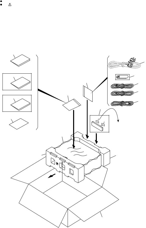
2.1 PACKING
B
9
|
1 |
|
10 |
6 |
|
|
12 |
|
|
3 |
|
C |
4 |
|
12 |
||
|
||
11 |
|
|
|
5 |
|
|
7 |
|
2 |
17 |
|
|
8 |
|
|
DV-989AVi-S/YXJRE Only |
|
D |
16 |
|
|
13 |
14 |
E
Front side
15
F
6 |
|
DV-989AVi-S |
|
|
1 |
2 |
|
3 |
4 |

|
|
5 |
6 |
PACKING parts List |
|
||
Mark No. |
Description |
Part No. |
|
> |
1 |
Power Cable |
See Contrast table (2) |
NSP |
2 |
Warranty Card |
See Contrast table (2) |
|
3 |
Stereo Audio Cable (L = 1.5 m) VDE1064 |
|
|
4 |
Video Cable (L = 1.5 m) |
VDE1065 |
|
5 |
4-pin S400 i.LINK Cable |
VDE1076 |
|
|
(L = 1.5 m) |
|
NSP |
6 |
Dry Cell Battery |
See Contrast table (2) |
|
7 |
Remote Control |
See Contrast table (2) |
|
8 |
Battery Cover |
See Contrast table (2) |
|
9 |
Operating Instructions |
See Contrast table (2) |
|
10 |
Operating Instructions |
See Contrast table (2) |
|
7 |
8 |
|
|
Mark No. |
Description |
Part No. |
|
|
11 |
Operating Instructions |
See Contrast table (2) |
A |
|
12 |
Polyethylene Bag |
VHL1051 |
||
|
||||
13 |
Pad F |
VHA1394 |
|
|
14 |
Pad R |
VHA1395 |
|
|
15 |
Packing Case |
See Contrast table (2) |
|
|
16 |
Mirror Mat Sheet |
AHG7010 |
|
|
17 |
Remote Card |
See Contrast table (2) |
|
B
(2) CONTRAST TABLE
DV-989AVi-S/WYXJ, DV-989AVi-S/YXJRE, DV-989-AVi-G/HLXJ and DV-989AVi-S/WPWXJ are constructed the same except for the following :
Mark |
No. |
Symbol and Description |
DV-989AVi-S |
DV-989AVi-S |
DV-989AVi-G |
DV-989AVi-S |
|
/WYXJ |
/YXJRE |
/HLXJ |
/WPWXJ |
||||
|
|
|
|||||
|
|
|
|
|
|
|
|
> |
1 |
Power Cable |
ADG7062 |
ADG7062 |
ADG1154 |
ADG7099 |
|
NSP |
2 |
Warranty Card |
ARY7065 |
ARY7065 |
Not used |
Not used |
|
NSP |
6 |
Dry Cell Battery |
VEM1021 |
VEM1021 |
VEM1031 |
VEM1031 |
|
|
7 |
Remote Control |
VXX2894 |
VXX2894 |
VXX2896 |
VXX2894 |
|
|
8 |
Battery Cover |
VNK4936 |
VNK4936 |
VNK4422 |
VNK4936 |
|
|
9 |
Operating Instructions (English, Spanish) |
VRD1205 |
Not used |
Not used |
Not used |
|
|
9 |
Operating Instructions (English) |
Not used |
Not used |
VRB1402 |
VRB1402 |
|
|
9 |
Operating Instructions (Russia) |
Not used |
VRC1296 |
Not used |
Not used |
|
|
10 |
Operating Instructions (French,German) |
VRD1206 |
Not used |
Not used |
Not used |
|
|
10 |
Operating Instructions (Chinese) |
Not used |
Not used |
VRC1290 |
Not used |
|
|
11 |
Operating Instructions (Italian,Dutch) |
VRD1207 |
Not used |
Not used |
Not used |
|
|
15 |
Packing Case |
VHG2644 |
VHG2644 |
VHG2659 |
VHG2690 |
|
|
17 |
Remote Card (Russia) |
Not used |
Not used |
ARW7322 |
Not used |
|
|
|
|
|
|
|
|
C
D
E
F
|
|
|
|
|
|
|
|
|
DV-989AVi-S |
7 |
7 |
||
5 |
6 |
|
|
|
8 |
|
A
B
C
D
E
F
|
1 |
2 |
3 |
4 |
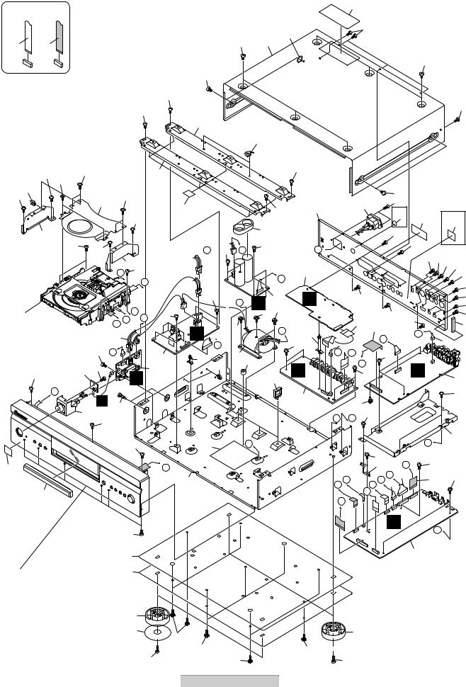
2.2 EXTERIOR SECTION |
|
|
|
|
CONTACT-NON SIDE |
CONTACTSIDE |
|
|
47 |
|
62 |
59 |
||
|
|
|
||
|
|
|
|
|
|
|
56 |
27 |
|
56
56
48
59
48
23
24
48 |
54 |
49 |
|
|
23 |
18 |
|
|
|
|
|
|
|
49 |
|
|
|
48 |
|
30 |
|
|
|
|
|
|
|
|
|
|
|
|
|
48 |
|
34 |
|
|
|
|
|
|
55 |
48 |
|
|
|
|
|
|
|
|
|
|
|
|
35 |
|
|
|
|
|
H |
55 |
|
|
|
|
|
|
|
|
|
|
|
G |
|
7 |
|
|
|
C |
55 |
|
|
D E |
F |
||
Refer to |
|
|
|
|
|
"2.4 LOADER MECHA. ASSY". 17 |
|
|
|||
|
|
55 |
B |
|
6 |
|
|
|
|
|
|
59 |
|
39 51 |
|
G |
5 |
|
|
|
|
||
|
|
|
|
|
|
B
J 22
43
59
59
45 |
A |
38
|
59 |
|
25 |
Refer to |
26 |
|
|
"2.3 FRONT PANEL SECTION". |
|
|
19 |
|
64 |
41
 L 55
L 55
55
H 
I
21
18
36
29
53
53
48
37
J 55
|
|
K |
F |
I |
4 |
58 |
||
|
|
|
|
|
53 |
58 J
14 37
40
C
50 53
8 |
|
DV-989AVi-S |
1 |
2 |
|
48
28
L 
9
D
32
57
B
3
|
|
|
56 |
(HLXJ |
|
(YXJRE |
|
|
|
8 |
60 |
|
|||
|
|
Only) |
|
|
Only) |
||
|
|
65 |
|
|
|||
|
|
|
46 |
|
|
63 |
|
|
|
|
|
|
|
||
|
|
|
|
|
|
|
|
|
|
51 |
|
|
|
|
|
|
|
|
|
51 |
|
|
|
|
|
|
|
59 51 |
59 61 |
||
|
|
|
|
|
|
|
|
|
|
|
|
|
|
|
51 |
|
|
|
|
|
|
|
59 |
|
|
59 |
|
|
|
|
59 |
|
|
|
|
|
|
|
52 |
|
|
59 |
|
|
|
59 |
|
|
|
15 |
59 |
|
|
42 |
|
|
|
12 |
|
|
|
|
|
|
|
|
M |
|
|
|
|
|
|
K |
|
|
16 |
||
|
|
|
|
|
|||
|
|
|
|
|
|
||
M |
N |
57 |
|
|
|
|
|
|
|
|
|
|
|
|
|
|
|
O |
|
C |
|
|
|
|
|
57 |
|
|
|
2 |
|
|
|
|
|
|
|
|
|
|
|
|
|
|
|
|
59 |
|
33 |
|
|
|
|
|
|
P |
Q |
59 |
|
|
|
|
|
|
|
|
|
|
|
||
|
|
|
|
P |
|
|
32 |
|
|
|
|
|
|
|
|
|
|
57 |
N |
|
57 |
|
|
|
|
31 |
|
|
|
||
|
|
10 |
|
|
|
|
|
D E |
|
I |
|
13 |
|
57 |
|
|
G H 11 |
|
|
|
|||
|
|
A |
|
|
|
|
|
O |
|
|
|
|
|
|
|
|
|
A |
|
Q |
|
|
|
|
|
|
|
|
|
|
|
|
|
|
|
1 |
|
|
|
19
53  64
64
50
3 |
4 |

|
|
5 |
6 |
EXTERIOR SECTION parts List |
|
||
Mark No. |
Description |
Part No. |
|
|
1 |
DVDM Assy |
VWS1601 |
|
2 |
AJKB Assy |
See Contrast table (2) |
|
3 |
VJKB Assy |
See Contrast table (2) |
|
4 |
PS Assy |
VWV2153 |
|
5 |
MSWB Assy |
VWG2548 |
> |
6 |
POWER SUPPLY Unit |
VWR1397 |
NSP 7 |
LOADER MECHA. Assy |
VWT1218 |
|
> |
8 |
AC Inlet Assy |
See Contrast table (2) |
|
9 |
SCRB Assy |
See Contrast table (2) |
|
10 |
Connector Assy(13P) |
VKP2378 |
|
11 |
Connector Assy |
PG05KK-E30 |
|
12 |
FFC (31P, AVKB) |
VDA2102 |
|
13 |
FFC (23P, VJKB) |
VDA1972 |
> |
14 |
Power Transformer |
VTT1169 |
|
15 |
FFC (19P, SCRB) |
See Contrast table (2) |
|
16 |
Connector Assy(3P) |
See Contrast table (2) |
> |
17 |
Housing Assy (2P) |
VKP2379 |
|
18 |
Mini Clamp |
AEC7373 |
|
19 |
Insulator |
See Contrast table (2) |
|
20 |
• • • • |
|
|
21 |
PCB Support |
VEC2184 |
NSP 22 |
PCB Holder |
PNW2029 |
|
NSP 23 |
Beam 989 |
VNE2408 |
|
|
24 |
Mini Clamp 2 |
AEC7507 |
NSP 25 |
Bottom Plate |
VNA2836 |
|
NSP 26 |
Bottom Plate 989B |
VNA2852 |
|
|
27 |
Bonnet |
See Contrast table (2) |
|
28 |
Rear Panel |
See Contrast table (2) |
NSP 29 |
Chassis 989 |
See Contrast table (2) |
|
NSP 30 |
Mechanism Cover |
VNE2410 |
|
NSP 31 |
PCB Angle |
VNE2409 |
|
|
32 |
PCB Holder AJ |
VNE2330 |
|
33 |
Card Spacer |
AEC7214 |
|
7 |
8 |
Mark No. |
Description |
Part No. |
NSP 34 |
MECHA Angle L |
VNE2411 |
NSP 35 |
MECHA Angle R |
VNE2412 |
36 |
Protection Barrier |
VEC2485 |
NSP 37 |
Spacer |
AEB7092 |
38 |
Tray Panel |
See Contrast table (2) |
39 |
PLED Assy |
VWG2557 |
40 |
Wire Saddle |
VEC2310 |
41 |
Beam Spacer 989 |
VEC2499 |
42 |
Gasket 3*5*80 |
VEC2501 |
43 |
Power Button Assy |
See Contrast table (2) |
44 |
• • • • |
|
NSP 45 |
Energy Star Label |
See Contrast table (2) |
NSP 46 |
ID Label Assy |
VXW1004 |
47 |
Laser Caution Label |
VRW2257 |
48 |
Screw 3x6 B T (FE) |
ABA1192 |
49 |
Screw |
IBZ30P080FTC |
50 |
Screw |
BBZ30P100FCC |
50 |
Screw (HLXJ Only)) |
BSZ40P200FCC |
51 |
Screw |
PPZ30P080FCC |
52 |
Screw |
PCZ26P060FCC |
53 |
Screw (3x9 BT) |
ABA7101 |
54 |
Screw |
VBA1044 |
55 |
Screw |
BBZ30P080FCC |
56 |
Screw |
BCZ40P060FNI |
57 |
Screw (3x8 BT) |
ABA7017 |
58 |
Screw |
ABA1200 |
59 |
Screw |
BBT30P100FCC |
60 |
Screw |
CBZ30P080FCC |
61 |
Screw |
PCZ30P060FCC |
62 |
Toothed Lock Washers |
WH40FNI |
63 |
Region Label (YXJRE Only) |
VRW2259 |
64 |
Cushion |
See Contrast table (2) |
NSP 65 |
SISIR Label (HLXJ Only) |
VRW2245 |
(2) CONTRAST TABLE
DV-989AVi-S/WYXJ, DV-989AVi-S/YXJRE, DV-989-AVi-G/HLXJ and DV-989AVi-S/WPWXJ are constructed the same except for the following :
Mark |
No. |
Symbol and Description |
|
|
DV-989AVi-S |
|
DV-989AVi-S |
DV-989AVi-G |
DV-989AVi-S |
|
||
|
|
/WYXJ5 |
|
/YXJRE5 |
/HLXJ |
/WPWXJ |
|
|||||
|
|
|
|
|
|
|
||||||
|
|
|
|
|
|
|
|
|
|
|
||
|
2 |
AJKB Assy |
|
|
VWV2149 |
|
VWV2149 |
VWV2148 |
VWV2148 |
|
||
|
3 |
VJKB Assy |
|
|
VWV2152 |
|
VWV2152 |
VWV2150 |
VWV2151 |
|
||
> |
8 |
AC Inlet Assy |
|
|
VKP2364 |
|
VKP2364 |
VKP2367 |
VKP2367 |
|
||
|
9 |
SCRB Assy |
|
|
VWV1992 |
|
VWV1992 |
Not used |
Not used |
|
||
|
15 |
FFC (19P, SCRB) |
|
|
VDA1973 |
|
VDA1973 |
Not used |
Not used |
|
||
|
16 |
Connector Assy(3P) |
|
|
PG03KK-E15 |
|
PG03KK-E15 |
Not used |
Not used |
|
||
|
19 |
Insulator |
|
|
PNW2766 |
|
PNW2766 |
ANL7028 |
PNW2766 |
|
||
|
27 |
Bonnet |
|
|
VXX3077 |
|
VXX3077 |
VXX3078 |
VXX3077 |
|
||
|
28 |
Rear Panel |
|
|
VNA2837 |
|
VNA2837 |
VNA2841 |
VNA2873 |
|
||
NSP |
29 |
Chassis 989 |
|
|
VNA2843 |
|
VNA2843 |
VNA2863 |
VNA2843 |
|
||
|
38 |
Tray Panel |
|
|
VNK5850 |
|
VNK5850 |
VNK5849 |
VNK5850 |
|
||
|
43 |
Power Button Assy |
|
|
VXA2724 |
|
VXA2724 |
VXA2725 |
VXA2724 |
|
||
NSP |
45 |
Energy Star Label |
|
|
Not used |
|
Not used |
Not used |
AAX8022 |
|
||
|
64 |
Cushion |
|
|
PNM1339 |
|
PNM1339 |
AEC7224 |
PNM1339 |
|
||
|
|
|
|
|
|
|
|
|
|
|||
|
|
|
|
|
|
|
|
|
|
|
|
|
|
|
|
|
|
DV-989AVi-S |
7 |
|
9 |
||||
|
|
5 |
6 |
|
|
|
|
|
|
8 |
||
A
B
C
D
E
F
A
B
C
D
E
F
1 |
2 |
3 |
4 |
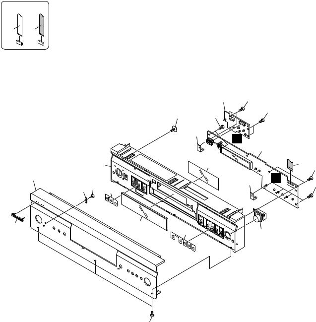
2.3 FRONT PANEL SECTION
NON-CONTACT SIDE |
CONTACT SIDE |
|
|
2 |
11 |
|
|
15 |
11 |
|
11 |
|
|
|
||
|
|
4 |
F |
|
|
|
|
|
|
|
|
|
|
1 |
9(1/2) |
|
7 |
|
3 |
|
|
|
11 |
|
|
|
|
|
|
6 |
|
|
4 |
E |
9(2/2) 10 |
|
|
11 |
|
12 |
|
|
||
|
|
|
5 |
8 |
|
13 |
14 |
11
10 |
|
DV-989AVi-S |
|
|
1 |
2 |
|
3 |
4 |
5 6 7 8
FRONT PANEL SECTION parts List
Mark No. |
Description |
Part No. |
Mark No. |
Description |
Part No. |
1 |
FLKY Assy |
See Contrast table (2) |
NSP 10 |
LED Lens |
VNK5073 |
2 |
KEYB Assy |
VWG2558 |
|
|
|
3 |
FFC (17P, FLKB) |
VDA2089 |
11 |
Screw |
PPZ30P080FCC |
4 |
Earth Plate S |
VNF1131 |
12 |
Button Sheet L |
VED1014 |
5 |
Pioneer Name Plate |
See Contrast table (2) |
13 |
Button Sheet R |
VED1015 |
|
|
|
14 |
Standby BTN V1 (P) |
See Contrast table (2) |
6 |
Aluminum Panel |
See Contrast table (2) |
15 |
Screw |
ABA7110 |
7 |
FL Filter |
VEC2482 |
|
|
|
8 |
D Window |
VEC2492 |
|
|
|
9 |
Panel Base Assy |
See Contrast table (2) |
|
|
|
(2) CONTRAST TABLE
DV-989AVi-S/WYXJ, DV-989AVi-S/YXJRE, DV-989-AVi-G/HLXJ and DV-989AVi-S/WPWXJ are constructed the same except for the following :
Mark |
No. |
Symbol and Description |
DV-989AVi-S |
DV-989AVi-S |
DV-989AVi-G |
DV-989AVi-S |
|
/WYXJ |
/YXJRE |
/HLXJ |
/WPWXJ |
||||
|
|
|
|||||
|
|
|
|
|
|
|
|
|
1 |
FLKY Assy |
VWG2552 |
VWG2552 |
VWG2554 |
VWG2554 |
|
|
5 |
Pioneer Name Plate |
VAM1124 |
VAM1124 |
PAN1377 |
VAM1124 |
|
|
6 |
Aluminum Panel |
VAH1430 |
VAH1430 |
VAH1434 |
VAH1430 |
|
|
9 |
Panel Base Assy |
VXA2721 |
VXA2721 |
VXA2722 |
VXA2721 |
|
|
14 |
Standby BTN V1 (P) |
XAD3191 |
XAD3191 |
XAD3186 |
XAD3191 |
|
|
|
|
|
|
|
|
A
B
C
D
E
F
|
|
|
|
|
|
|
|
|
DV-989AVi-S |
7 |
11 |
||
5 |
6 |
|
|
|
8 |
|
|
|
1 |
2 |
|
|
3 |
|
4 |
|
|
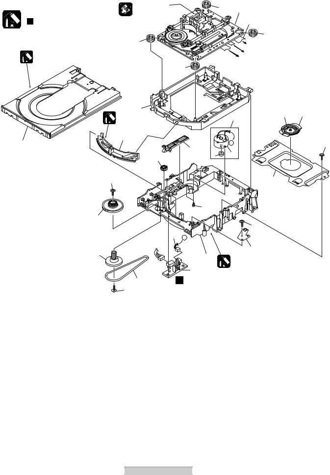
2.4 LOAD MECHA. ASSY |
|
|
|
|
|
|
||
|
Note : |
|
Cleaning paper |
|
|
6 |
1 Refer to |
|
|
A |
Refer to |
|
|
|
|
||||
GED-008 |
|
|
|
|
|
||||
|
|
|
"2.5 TRAVERSE MECHA. ASSY-S". |
||||||
|
|
|
|
||||||
|
" |
Application of Lubricant". |
|
|
|
5 |
|
|
|
|
|
|
|
|
|
|
6 |
|
|
|
|
|
6 |
|
|
|
To DVDM CN101 (Pickup Assy-S) |
||
|
|
|
|
|
|
|
|||
|
|
Daifree |
|
|
|
|
To DVDM CN104 (Stepping Motor) |
||
|
|
|
|
|
|
To DVDM CN105 (Spindle Motor) |
|
||
|
|
GEM1036 |
|
|
|
|
|
||
|
|
|
|
|
|
|
|
|
|
|
|
|
|
|
6 |
|
|
|
|
B |
|
|
|
|
|
|
|
|
|
|
|
|
10 |
|
|
|
|
16 |
18 |
|
|
|
Lubricating Oil |
|
|
|
2 |
||
|
|
|
|
|
|
|
|
||
|
|
|
GYA1001 |
|
|
|
|
|
|
|
|
|
|
|
|
|
|
|
|
|
21 |
|
11 |
|
|
|
A |
|
|
|
|
|
|
15 |
|
|
20 |
||
|
|
|
|
|
|
4 |
|
|
|
|
|
|
14 |
|
|
3 |
|
|
|
|
|
|
|
|
|
|
|
|
|
C |
|
|
20 |
|
|
|
|
17 |
|
|
|
|
|
|
|
|
|
|
|
|
|
|
|
|
|
19 |
|
|
|
|
|
|
13 |
|
|
|
|
|
|
|
|
|
|
|
|
|
20 |
|
|
|
|
|
|
23 |
A |
|
|
|
|
|
|
|
|
|
|
|
|
|
|
|
|
|
12 |
|
|
|
8 |
|
|
|
|
|
|
|
9 |
|
|
|
|
|
|
|
|
|
|
Lubricating Oil |
|
|
|
|
|
|
|
|
|
|
|
|
|
D |
|
|
|
|
22 |
|
GYA1001 |
|
|
|
|
|
|
|
|
|
|
|
|
|
|
|
7 |
|
K |
|
|
|
|
|
|
|
20 |
|
|
|
|
|
|
|
LOADER MECHA. ASSY parts List |
|
|
|
|
|
|
||
|
Mark No. |
Description |
Part No. |
Mark No. |
Description |
Part No. |
|
||
|
1 |
Traverse Mecha. Assy-S |
VXX2909 |
|
17 |
Bridge |
|
VNE2343 |
|
|
2 |
Loading Motor Assy |
VXX2912 |
|
18 |
Clamper |
|
VNL1924 |
|
|
3 |
Motor Pulley |
PNW1634 |
|
19 |
Screw |
|
JGZ17P028FMC |
|
|
4 |
Motor |
VXM1107 |
|
20 |
Screw |
|
VBA1094 |
|
E |
5 |
Flexible Cable (24P) |
VDA1947 |
|
21 |
Tray |
|
VNL1920 |
|
|
|
|
|
|
|
|
|||
|
6 |
Floating Rubber |
VEB1351 |
|
NSP 22 |
LOAB Assy |
|
VWG2426 |
|
|
7 |
Belt |
VEB1358 |
|
23 |
Connector Assy (2P) |
VKP2253 |
|
|
|
8 |
Stabilizer |
VNE2253 |
|
|
|
|
|
|
|
9 |
Loading Base |
VNL1917 |
|
|
|
|
|
|
|
10 |
Float Base DVD |
VNL1918 |
|
|
|
|
|
|
|
11 |
Drive Cam |
VNL1919 |
|
|
|
|
|
|
|
12 |
Gear Pulley |
VNL1921 |
|
|
|
|
|
|
|
13 |
Loading Gear |
VNL1922 |
|
|
|
|
|
|
F |
14 |
Drive Gear |
VNL1923 |
|
|
|
|
|
|
|
15 |
SW Lever |
VNL1925 |
|
|
|
|
|
|
|
16 |
Clamper Plate |
VNE2342 |
|
|
|
|
|
|
|
12 |
|
DV-989AVi-S |
|
|
|
|
|
|
|
|
1 |
2 |
|
|
3 |
|
4 |
|

5 |
6 |
7 |
8 |
|
|
Application of Lubricant |
|
|
|
||
|
|
Lubricating Oil |
|
A |
|
|
|
|
|
||
|
|
GYA1001 |
|
|
|
|
|
Around the shaft |
|
|
|
|
No. 11 |
|
|
|
|
|
Loading Base |
|
|
|
|
|
|
|
|
B |
|
|
|
Lubricating Oil |
|
|
|
|
|
GYA1001 |
|
|
|
|
No. 13 |
Lubricating Oil |
Lubricating Oil |
|
|
Lubricating Oil |
GYA1001 |
GYA1001 |
C |
||
Drive Cam |
Inner side of a ditch |
Inner side of a ditch |
|||
|
|||||
GYA1001 |
|
|
|
|
|
Lubricating Oil |
Lubricating Oil |
|
No. 13 |
|
|
GYA1001 |
GYA1001 |
|
Drive Cam |
|
|
Front View |
|
Rear View |
|
D |
|
|
|
|
|
||
No. 23 |
Daifree |
No. 23 |
Daifree |
|
|
GEM1036 |
|
||||
GEM1036 |
|
||||
Tray |
Tray |
Concave of unevenness |
|
||
Concave of unevenness |
|
||||
|
|
|
|
||
|
|
|
|
E |
|
|
|
Inner side of a ditch |
|
||
|
|
Daifree |
|
|
|
|
|
GEM1036 |
|
|
|
Top View |
|
Bottom View |
Side of the rib |
|
|
|
Concave of unevenness |
|
|
||
|
|
|
|
||
|
Daifree |
|
Daifree |
|
|
|
|
GEM1036 |
|
||
|
GEM1036 |
|
F |
||
|
|
|
|||
|
|
DV-989AVi-S |
|
13 |
|
5 |
6 |
7 |
8 |
|
|

1 |
2 |
3 |
4 |
2.5 TRAVERSE MECHA. ASSY-S
A
17
10
17
B
1
13 |
16 |
|
C
D
E
11
Cleaning paper
GED-008 Cleaning liquid
GEM1004
15 (Torque : 0.15 ± 0.01 N•m)
Silicone Adhesive
GEM1037
3
8
17
10
7
6
To
DVDM CN101
(Pickup Assy)
14
9
4 (Adjustment screw)
|
|
Silicone Adhesive |
|
|
|
GEM1037 |
|
5 |
Screw Tight |
15 (Torque : 0.15 ± 0.01 N•m) |
|
GYL1001 |
|||
(Adjustment |
|||
|
|
||
spring) |
|
|
To DVDM CN105
(Spindle Motor)
16
2
To
DVDM CN104
(Stepping Motor)
NON-CONTACT SIDE |
CONTACT SIDE |
F
14 |
|
DV-989AVi-S |
|
|
1 |
2 |
|
3 |
4 |

5 6 7 8
TRAVERSE MECHA. ASSY-S parts List
Mark No. |
Description |
Part No. |
1 |
Spindle Motor |
VXM1099 |
2 |
Stepping Motor |
A |
VXM1101 |
||
3 |
Pickup Assy-S |
OXX8005 |
4 |
Skew Screw |
VBA1080 |
5 |
Skew Spring |
VBH1335 |
6 |
Guide Bar |
VLL1514 |
7 |
Sub Guide Bar |
VLL1515 |
8 |
Leaf Spring |
VNC1023 |
9 |
Joint Spring |
VNC1019 |
10 |
Support Spring |
VNC1020 |
|
|
B |
NSP 11 |
Mecha.Chassis |
VNE2248 |
12 |
Damper Sheet |
VEB1335 |
13 |
Spacer |
VNL1913 |
14 |
Joint 03 |
VNL1949 |
15 |
Tapping Screw |
OBA8021 |
16 |
Screw |
BBZ20P050FZK |
17 |
Screw |
PMA26P100FMC |
C
D
E
F
|
|
|
|
|
|
|
|
|
DV-989AVi-S |
7 |
15 |
||
5 |
6 |
|
|
|
8 |
|
1 |
2 |
3 |
4 |
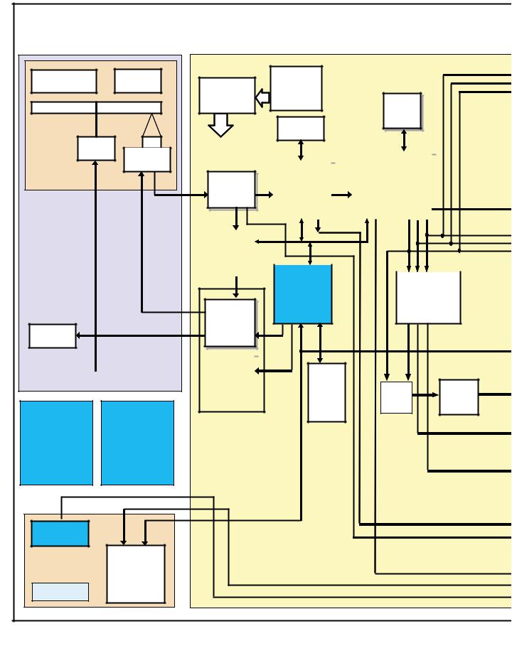
3. BLOCK DIAGRAM AND SCHEMATIC DIAGRAM
3.1 OVERAL BLOCK DIAGRAM
A
DV-989AVi BlockDiagram |
|
|
|
|
DVDM BOARD |
TRAVERSE |
PICK UP |
CPLD IC |
|
|
LC4032VAA |
|
|
3.3V (Macnica) |
B
SPDL |
PU |
MOTOR |
STEPPING |
|
MOTOR |
RF IC
LA9704W
5V
C |
SERVO |
||
DSP |
|||
|
LC78652W |
||
|
5&3.3V |
||
|
|
|
|
FTS
DRIVER
LOADING |
M56788AFP |
|
6&12V |
||
MOTOR |
||
|
D |
|
|
SPDL |
|
|
|
|
||
|
|
DRIVER |
|
|
|
|
|
||
|
|
|
BA6664FM |
|
|
|
|
6&5V |
|
|
|
|
|
|
Power Supply |
AUDIO |
|
||
Board |
TRANS |
|||
(Murata) (Kitamura)
E
IR(SHARP) FLKB
3V,H=12.9mm Board
|
FL |
|
FL Tube |
||
CONTROL |
||
Display |
||
CPU |
||
|
|
PE5314C
KEY Board 3.3V Counter
F
CLK |
|
|
Generator |
|
|
SM8707DV |
64M |
|
3.3V (NPC) |
||
SDRAM |
||
|
||
16M |
3.3V |
|
SDRAM |
|
|
|
|
MPEG2 DECODER |
|
|
|
|
|
|
|
DVD |
|
MITSUBISHIAV1 |
|
|
DECODER |
|
(DVD-A,DTS,TPP) |
|
|
(CPPM,CPRM) |
|
(Progressive Scan) |
|
|
EBY-CHIP |
|
M65776BFP |
|
|
PE5286B |
|
3.3V&1.8V |
|
|
|
|
||
|
|
|
|
|
|
RF(SACD) |
|
SYSTEM |
|
|
|
Audio DSP |
|
CONTROL |
|
|
|
XCA56367PV150 |
|
CPU |
|
|
|
|
|
FR30 |
|
3.3V&1.8V |
PD6345A
16M |
|
|
|
PGM |
CD |
AQE |
|
FLASH |
|||
Direct |
PD0274A |
||
MEMORY |
|||
SW |
|
||
3.3V |
|
|
16 |
|
DV-989AVi-S |
|
|
1 |
2 |
|
3 |
4 |
5 |
6 |
7 |
8 |
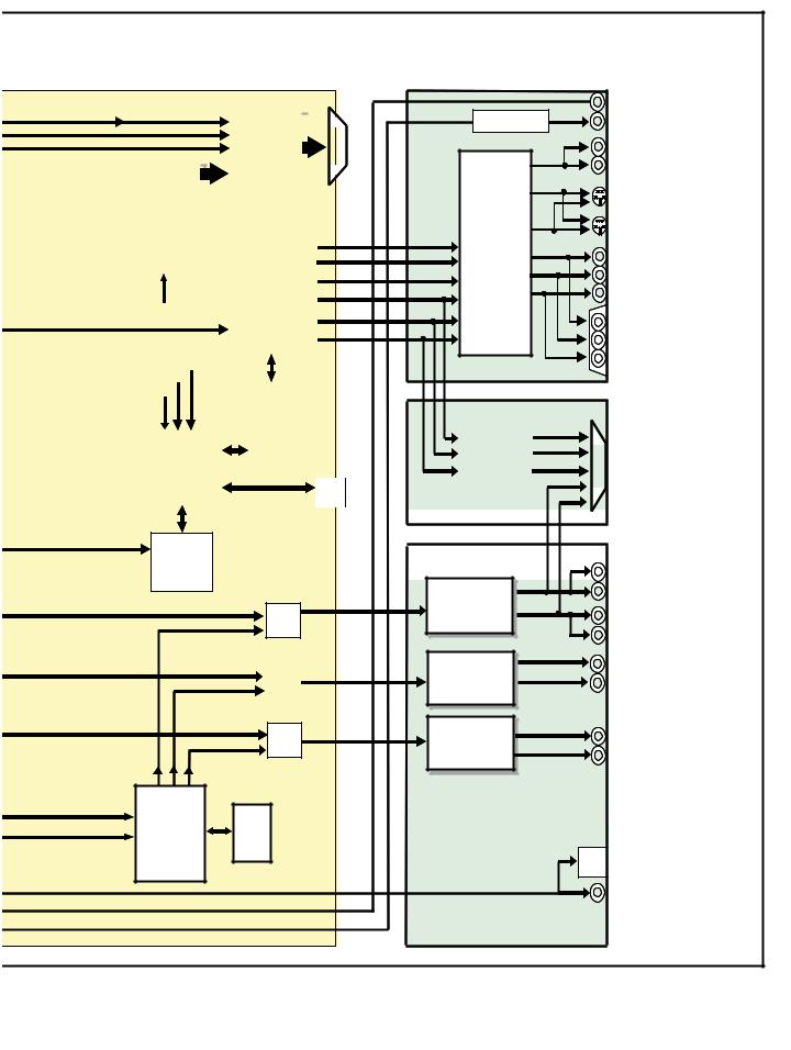
HDMI |
|
connector |
VJKB BOARD |
|
|
|
|
|
|
|
|
|
|
HDMI TX |
|
|
|
|
|
|
|
|
|
|
|
|
|
|
|
|
|
|
|
|
|
|
|||
|
|
|
|
|
|
|
|
|
|
SiI9030 |
|
|
|
|
|
|
|
|
|
|
|
|
|
|
|
|
|
|
|
|
|
|
|
||
|
|
|
|
|
|
|
|
|
|
|
|
|
|
|
|
||
|
|
|
|
|
|
|
|
|
|
|
|
|
|
|
|
|
|
|
RESOLUTIO |
|
|
|
|
|
|
|
|
|
|
||||||
|
|
|
|
|
|
|
|
|
|
|
|
||||||
|
N EXPO |
|
|
|
|
|
|
|
|
|
|
|
|||||
|
|
|
|
|
|
|
|
|
|
|
|
||||||
|
|
lC |
|
|
|
|
|
|
|
|
|
|
|||||
|
(T-REX) |
|
|
|
|
|
|
|
|
|
|
||||||
|
PD0280B |
|
|
I/P Processer |
|
|
V |
||||||||||
|
. |
|
|
|
|
|
|
|
|
|
&VIDEO |
|
|
SY |
|||
|
3.3V&2.5V |
|
|
|
|
|
|||||||||||
|
|
|
|
|
|
|
|
|
|
|
DAC |
|
|
SC |
|||
|
|
|
|
|
|
|
|
|
|
|
|||||||
|
|
|
|
|
|
|
|
|
|
|
(PRO-3) |
|
|
|
|||
|
|
|
|
|
|
|
|
|
|
CM0039AF |
|
Cb/B |
|||||
|
|
|
|
|
|
|
|
|
|
|
(PVC) |
|
|||||
|
|
|
|
|
|
|
|
|
|
|
|
Cr/R |
|||||
|
|
|
|
|
|
|
|
|
|
1.8V&3.3V |
|
||||||
|
|
|
|
|
|
|
|
|
|
|
|
|
|||||
|
|
|
|
|
|
|
|
|
|
|
|
|
|
|
|
|
|
|
|
|
|
|
|
|
|
|
|
|
|
|
|
|
|
|
|
|
|
|
|
|
|
|
|
|
|
|
64M |
|
|
|
|
||
|
|
|
|
|
|
|
|
|
|
|
|
|
|
|
|||
|
|
|
|
|
|
|
|
|
|
|
SDRAM |
|
|
|
|
||
|
|
|
|
|
|
|
|
|
|
|
|
|
|
|
|
|
|
|
|
Mercury |
|
|
4M |
|
|
|
|||||||||
|
|
TSB43CA- |
|
|
Flash ROM |
|
|
|
|||||||||
|
|
42GGW |
|
|
|
|
|
|
|
|
|
||||||
|
|
|
|
|
|
|
|
i-Link |
|
||||||||
|
|
3.3V&1.8V |
|
|
|
|
|
|
|
||||||||
|
|
|
|
|
|
|
|
Connector |
|||||||||
|
|
|
|
|
|
|
|
|
|
|
|
|
|
|
|||
|
|
|
|
|
|
|
|
|
|
|
|
|
|
|
|
|
|
Host
CPU
PD5787A
FL/FR(AV1) FL/FR
FL/FR(SACD) SW
SL/SR(AV1) |
SW |
SL/SR |
|
SL/ SR(SACD |
|||
|
|||
|
|
|
SW/C(AV1) SW/C
SW/C(SACD) SW
|
SR IN |
3-5 Change |
SR 0UT |
|
V |
VIDEO OUTx2 |
|
VIDEO |
Y |
|
|
|
S-VIDEO OUTx2 |
||
AMP |
SC |
||
|
|||
DRIVER |
SY |
|
|
6ch OUT |
COMPONENT OUT |
||
|
Cb |
||
|
(Progressive/Interlace) |
||
LA73054 |
Cr |
||
|
|
D1/D2 OUT |
SCRB BOARD (WY Only)
|
VIDEO |
R |
|
|
||
|
AMP |
G |
|
|
|
|
|
|
|
|
|||
|
DRIVER |
B |
|
|
|
SCART IN/OUT*2 |
|
6ch OUT |
FL |
|
|
|
|
|
LA73054 |
FR |
|
|
||
|
|
|
|
|
|
|
|
|
|
|
|
|
|
|
|
|
|
|
|
|
192k,24bit, |
|
FRONT Lchx2 |
|
2chDAC |
|
|
|
PCM1738E(BB |
|
FRONT Rchx2 |
|
|
|
||
192k,24bit, |
SL |
REAR Lch |
|
SR |
|||
2chDAC |
REAR Rch |
||
PCM1738E(BB |
|
|
|
192k,24bit, |
SW |
SUBWOOFER |
|
2chDAC |
C |
||
CENTER |
|||
PCM1738E(BB |
|||
|
|||
|
|
SACD |
|
Decoder |
16M |
CXD2753R |
SDRAM |
3.3V&2.5V |
3.3V |
(SONY) |
OPTICAL OUT |
|
COAXIAL OUT |
AJKB BOARD
A
B
C
D
E
F
|
|
|
|
|
|
|
|
|
DV-989AVi-S |
7 |
17 |
||
5 |
6 |
|
|
|
8 |
|
1 |
2 |
3 |
4 |
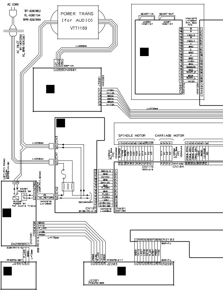
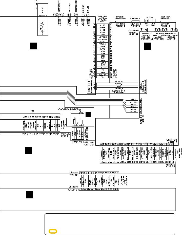
3.2 LOAB ASSY and OVERALL WIRING DIAGRAM
A
B
C
D
WYXJ, YXJRE Only
D
SCRB ASSY
(VWV1992)
I PS ASSY
(VWV2153)
H POWER SUPPLY |
LOADER ASSY |
|
Unit (VWR1397) |
||
|
E
F
G
MSWB ASSY
(VWG2548)
J |
F KEYB ASSY |
PLED ASSY |
(VWG2558) |
(VWG2557) |
|
18 |
|
DV-989AVi-S |
|
|
1 |
2 |
|
3 |
4 |
5 |
6 |
7 |
8 |
B VJKB ASSY
(WYXJ, YXJRE : VWV2152) (HLXJ : VWV2150) (WPWXJ : VWV2151)
C
AJKB ASSY
(WYXJ, YXJRE
:VWV2149) (HLXJ, WPWXJ
:VWV2148)
WYXJ, YXJRE Only
CN602 |
M |
|
|
|
|
+ |
|
|
K |
LOAB ASSY |
|
|
1 |
2 |
CN602 |
||
S101 |
|
|
(VWG2426) |
||
|
|
|
|
||
|
|
|
|
CN601 |
|
A DVDM ASSY
(VWS1601)
LOADING
MOTOR ASSY
: VXX2872
A
B
C
D
E FLKY ASSY
(WYXJ, YXJRE : VWG2552) (HLXJ, WPWXJ : VWG2554)
÷When ordering service parts, be sure to refer to "EXPLODED VIEWS and PARTS LIST" or "PCB PARTS LIST".
÷The > mark found on some component parts indicates the importance of the safety factor of the part. Therefore, when replacing, be sure to use parts of identical designation.
÷: The power supply is shown with the marked box.
|
|
|
|
|
|
|
|
|
DV-989AVi-S |
7 |
19 |
||
5 |
6 |
|
|
|
8 |
|
E
F

1 |
2 |
3 |
4 |
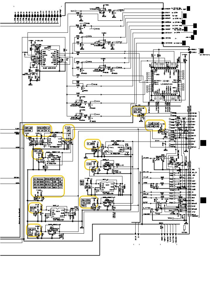
3.3 DVDM ASSY 1/6 [FTS BLOCK]
A
A 1/6 DVDM ASSY (VWS1601)
2
 RF_V
RF_V
RF_A
RF
RF
B |
1 |
|
RF |
||
|
4
RF

 F
F
 F
F
 T
T

 T
T 
C
to PU
RF
RF
RF
RF
RF
RF
D
E
K CN601 |
|
|
to CARRIAGE MOTOR |
F F |
T T |
MOTOR |
F |
T |
to SPINDLE |
|
|
F
|
|
|
|
|
|
|
|
|
|
|
|
|
|
|
|
|
|
|
|
|
|
|
|
|
|
|
|
|
|
|
|
|
|
|
|
|
|
|
|
|
|
|
|
|
|
|
|
|
|
|
|
|
|
|
|
|
|
|
|
|
|
|
|
|
|
|
|
|
|
|
|
|
A |
1/6 |
|
|
|
|
|
|
|
|
|
|
|
|
|
|
|
|
|
|
|
|
|
|
|
|
|
|
|
|
|
|
|
|
|
|
|
|
|
|
|
|
|
|
|
|
|
|
|
|
|
|
|
|
|
|
|
|
|
|
|
|
|
|
|
|
|
|
|
|
|
|
|
|
|
|
|
|
|
|
|
|
|
|
|
|
|
|
|
|
|
|
|
|
|
|
|
|
|
|
|
2/6 from / to FR (IC601) |
|
|
|
|
|
|
|
|
|
|
|
|
|
|
|
|
|
|
|
|
|||||||||||||||||||||
|
|
|
|
|
|
|
|
|
|
|
|
|
|
|
|
|
|
|
|
|
|
|
|
|
|
|
|
|
A |
|
|
|
|
|
|
|
|
|
|
|
|
|
|
|
|
|
|
|
|
||||||||||||||||||||||
|
|
|
|
|
|
|
|
|
|
|
|
|
|
|
|
|
|
|
|
|
|
|
|
|
|
|
|
|
|
|
|
|
|
|
|
|
|
|
|
|
|
|
|
|
|
|
|
|
|
||||||||||||||||||||||
20 |
|
|
|
|
|
|
|
|
|
|
|
|
|
|
|
|
|
|
|
|
|
|
|
|
|
|
|
|
|
|
|
|
|
|
|
|
|
|
|
|
|
|
|
|
|
|
|
|
|
|
|
|
|
|
|
|
|
|
|
|
|
|
|
|
|
|
|
|
|
|
|
|
|
|
|
|
|
|
|
|
|
|
|
|
|
|
|
|
|
DV-989AVi-S |
|
|
|
|
|
|
|
|
|
|
|
|
|
|
|
|
|
|
|
|
|
|
|
|
|
|
|
||||||||||||||||||||||||||
1 |
|
2 |
|
|
|
|
|
|
|
|
|
|
|
|
|
|
|
|
|
|
|
|
|
|
|
|
|
|
|
|
|
|
|
|
3 |
4 |
|||||||||||||||||||||||||||||||||||
5 |
6 |
7 |
8 |
A
RF_V
RF_V B
B
RF_A |
A 6/6 |
|
|
|
to SACD (IC1110) |
RF_A
AD
6
AD
RF_A |
5 |
|
|
|
F |
|
T |
7
RF  : RF SIGNAL ROUTE
RF_V  : RF (VIDEO) SIGNAL ROUTE
RF_A  : RF (AUDIO) SIGNAL ROUTE
AD  : AUDIO DATA SIGNAL ROUTE
DV-989AVi-S
5 |
6 |
A 3/6
A 2/6
A 3/6
A 2/6 |
8 |
9 |
|
|
10 11
F  : FOCUS SERVO LOOP LINE
T  : TRACKING SERVO LOOP LINE
S  : STEPPING SERVO LOOP LINE
7
A 3/6
to AVI (IC751)
C
A 2/6
from Clock Block
D
A 3/6 from EBY (IC701)
E
F
A 1/6
21
8
1 |
2 |
3 |
4 |
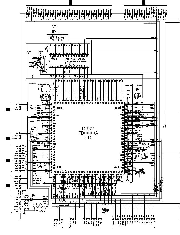
3.4 DVDM ASSY 2/6 [FR BLOCK]
A
B
C
D
E
to FTS DRIVER
to RF IC (IC101) to SPDL DRIVER
to Servo Block
A 3/6 to AV1 |
A 3/6 to EBY |
VYW2363 |
|
3/6 |
|
A |
|
3/6 |
|
A |
|
3/6 |
|
A |
|
3/6 |
|
A |
|
for FRASH |
|
F
|
A |
2/6 |
|
|
|
|
|
|
|
|
|
|
|
|
|
|
|
to |
CN901 |
|
|
A |
4/6 to Video Block |
|
A |
1/6 from SERVO DSP |
|||||
|
|
|
|
A |
4/6 |
|
|
|
|||||||
|
|
|
|
|
|
|
|
|
|
|
|
|
|
|
|
22 |
|
|
|
|
|
|
|
|
|
|
|
|
|
|
|
|
|
|
|
|
|
DV-989AVi-S |
|
|
|
|
|
||||
1 |
2 |
|
|
|
|
|
3 |
4 |
|||||||
5 |
6 |
7 |
8 |
|
A |
3/6 to EBY |
A |
|
|
|
|
A 6/6
A 3/6
A 6/6
A 3/6
A 1/6
A 3/6
 A 6/6
A 6/6
A 4/6
A 5/6
B
C
H CN101 from syps ASSY
D
E CN2101 to FLKB ASSY
E
|
|
|
|
|
|
|
|
|
|
|
|
|
|
|
|
|
|
|
|
|
|
|
|
|
|
|
|
|
|
|
|
|
|
|
|
|
|
|
|
|
|
|
|
|
|
|
|
|
|
|
|
|
|
|
|
|
|
|
|
|
|
|
|
|
|
|
|
|
|
|
|
|
|
|
|
|
|
|
|
|
|
|
|
|
|
|
|
|
|
|
|
|
|
|
|
A |
4/6 |
|
|
|
|
A |
5/6 |
||||||||||||||||
|
|
|
|
|
|
|
to FLKB |
|
|
|
|
to IC805 |
|||||||||||||||||
|
|
|
|
|
|
|
|
|
|
|
|
|
|
|
HOSTCON Serial |
||||||||||||||
|
2/6 DVDM ASSY (VWS1601) |
|
|
|
|
|
|
|
|
|
|
|
|
|
|
|
|
|
|
|
|
|
|
|
F |
||||
A |
|
|
|
|
|
|
|
|
|
|
|
|
|
|
|
|
|
|
|
|
|
|
|
2/6 |
|||||
|
|
|
|
|
|
|
|
|
|
|
|
|
|
|
|
|
|
|
|
|
|
|
|
|
|
|
|
A |
|
|
|
|
|
|
|
|
|
|
|
|
|
|
|
|
|
|
|
|
|
|
|
|
|
|
|
|
|
|
|
|
|
|
DV-989AVi-S |
|
|
|
|
7 |
|
23 |
|||||||||||||||||||
5 |
6 |
|
|
|
|
|
|
|
|
8 |
|
|
|||||||||||||||||

1 |
2 |
3 |
|
4 |
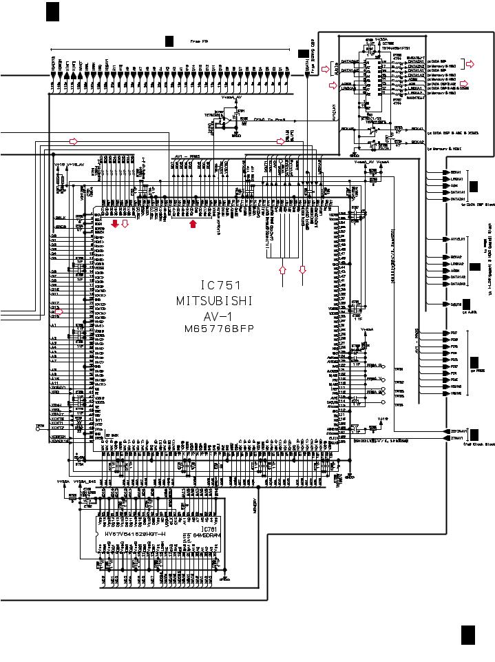
3.5 DVDM ASSY 3/6 [EBY/AV1 BLOCK] |
|
|
|
|
A |
|
|
|
|
|
|
A 6/6 |
|
A 2/6 |
B |
|
|
|
|
|
VD |
|
|
|
|
AD |
|
|
|
C |
|
|
|
|
|
VD |
AD |
|
|
|
|
|
D |
D |
|
|
|
|
|
|
|
|
AD |
AD |
|
|
|
|
|
D |
|
|
|
1/6 |
|
|
|
|
|
|
|
|
|
A |
2/6 |
|
|
RF_V |
RF_V |
A |
|
|
|
|
|
|
|
|
|
E |
|
|
|
|
F |
|
|
|
|
A 3/6 |
A 4/6 |
A 1/6 |
|
A 1/6 |
DV-989AVi-S |
|
|
|
|
24 |
|
|
|
|
1 |
2 |
3 |
|
4 |
5 |
6 |
7 |
8 |
A 3/6 DVDM ASSY (VWS1601) |
|
|
|
A 2/6 |
|
1/6 |
|
|
|
A |
|
|
|
D |
D |
|
|
D |
D |
D |
D |
|
|
|
|
|
A 2/6 |
VD AD |
VD |
|
|
|
|
|
4/6 |
|
|
|
A |
|
D |
D |
|
D |
|
|
A 6/6 |
|
|
|
|
|
|
|
A 4/6 |
|
|
|
A 4/6 |
A
B
C
D
E
RF_V : RF (VIDEO) SIGNAL ROUTE
VD : VIDEO DATA SIGNAL ROUTE
AD : AUDIO DATA SIGNAL ROUTE
D : AUDIO (DIGITAL) SIGNAL ROUTE
F
A 3/6
|
|
|
|
|
|
|
|
|
DV-989AVi-S |
7 |
25 |
||
5 |
6 |
|
|
|
8 |
|

1 |
2 |
3 |
4 |
3.6 DVDM ASSY 4/6 [i.LINK BLOCK]
A |
VD |
: VIDEO DATA SIGNAL ROUTE |
|
V |
: V SIGNAL ROUTE |
|
S_C |
: S-VIDEO OUT C SIGNAL ROUTE |
|
S_Y |
: S-VIDEO OUT Y SIGNAL ROUTE |
|
Cr/R |
: Cr/R SIGNAL ROUTE |
|
Y/G |
: Y/G SIGNAL ROUTE |
|
Cb/B |
: Cb/B SIGNAL ROUTE |
|
D |
: AUDIO (DIGITAL) SIGNAL ROUTE |
A 4/6 DVDM ASSY (VWS1601)
VD
B
VD
A 2/6
C
A 2/6
D
E
F
|
VD |
|
|
2/6 |
|
|
|
A |
|
|
|
|
Cr/R |
|
|
|
Cb/B |
|
|
|
Y/G |
|
|
|
S_C |
|
|
|
S_Y |
|
|
|
V |
|
|
A 4/6 |
|
DV-989AVi-S |
|
26 |
|
|
|
1 |
2 |
3 |
4 |

5 |
6 |
7 |
||
|
|
|
|
|
|
|
|
|
|
|
|
|
|
|
|
|
|
|
|
|
|
|
|
|
|
|
|
|
|
|
|
|
|
|
D |
D |
17 20
|
Cr/R |
|
Cb/B |
16 19 |
|
|
Y/G |
15 18 |
14 |
S_Y |
|
13 |
|
S_C
12
V
A 2/6
DV-989AVi-S
5 |
6 |
|
|
|
7 |
8
HDMI CONNECTOR

 A 2/6
A 2/6
B CN4101
A 4/6
27
8
A
B
C
D
E
F
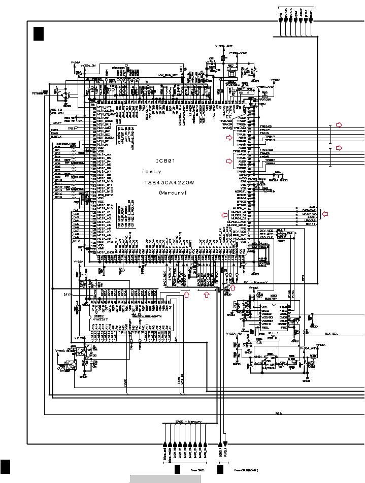
1 |
2 |
3 |
4 |
3.7 DVDM ASSY 5/6 [VIDEO BLOCK] |
|
|
|
A |
|
|
from AV1 |
|
A 5/6 DVDM ASSY (VWS1601) |
|
|
B |
|
|
|
|
|
|
D |
|
|
D |
|
|
|
|
D |
|
|
D |
|
C |
|
|
|
|
|
D |
D |
D |
|
|
|
|
|
D |
|
|
D |
D |
|
E |
|
|
|
F |
|
|
|
A 5/6 |
A 6/6 |
A 2/6 |
|
28 |
DV-989AVi-S |
|
|
1 |
2 |
3 |
4 |
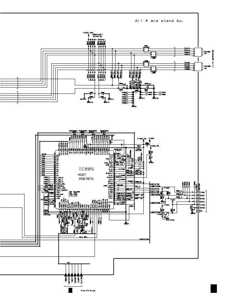
5 |
6 |
7 |
8 |
A
D 
B
D 
D 
D 
C
A 2/6 |
D
for FRASH
E
D : AUDIO (DIGITAL) SIGNAL ROUTE
F
A 5/6
|
|
|
|
|
|
|
|
|
DV-989AVi-S |
7 |
29 |
||
5 |
6 |
|
|
|
8 |
|
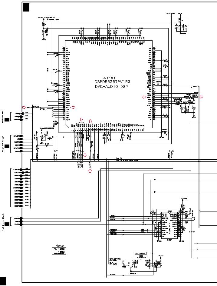
1 |
2 |
3 |
4 |
A
B
3.8 DVDM ASSY 6/6 [A-DSP/AQE/SACD BLOCK]
A 6/6 DVDM ASSY (VWS1601)
D
D
D
C |
D |
|
|
|
|
A 3/6 |
D |
D |
A 3/6
D
D
D
from FR
E
A 2/6
F
A 6/6
30 |
|
DV-989AVi-S |
|
|
1 |
2 |
|
3 |
4 |
Loading...