


 Loading...
Service Guide
SureSigns VS4
Vital Signs Monitor
Release A.06
English

SureSigns VS4
Vital Signs Monitor
S E R V I C E G U I D E
Release A.06
English

Notice
Proprietary Information
This document contains proprietary information, which is protected by copyright.
Copyright
© 2015 Koninklijke Philips N.V., All Rights Reserved
Trademark Acknowledgments
SureSigns is a registered trademark of Koninklijke Philips N.V. Other product names may be trademarks of their respective owners.
This software is based in part on the work of the Independent JPEG Group.
Manufacturer
Philips Medical Systems 3000 Minuteman Road Andover, MA 01810-1085 (978) 687-1501
Document Number 4535 645 72701
Warranty Disclaimer
The information contained in this document is subject to change without notice. Philips Medical Systems makes no warranty of any kind with regard to this material, including, but not limited to, the implied warranties of merchantability and fitness for a particular purpose. Philips Medical Systems shall not be liable for errors contained herein or for incidental or consequential damages in connection with the furnishing, performance, or use of this material.
Printing History
New editions of this document incorporate all material updated since the previous edition. Update packages may be issued between editions and contain replacement and additional pages to be merged by a revision date at the bottom of the page. Pages that are rearranged due to changes on a previous page are not considered revised.
The documentation printing date and part number indicate its current edition. The printing date changes when a new edition is printed. (Minor corrections and updates that are incorporated at reprint do not cause the date to change.) The document part number changes when extensive technical changes are incorporated.
First Edition. . . . . . . . . . . . . . . . . . . . . . . . . . . . . . . . . . . . . . . . . . . . . . . . . . . . . . . . . . . .October 2015
ii |
SureSigns VS4 Service Guide |

Conventions
This section describes the conventions used in this guide.
Text Formatting
The following typographical conventions are used in this guide.
Typeface |
Usage |
Example |
|
|
|
|
|
|
Bold |
System keys |
Press the Main Screen key. |
|
|
|
Special bold |
User interface text |
Open the System Menu. |
|
|
|
Italic |
Variables, |
• <product name>-<hardware |
|
document titles |
configuration>-<software version>.cfg |
|
|
• SureSigns VM Series Instructions for Use |
|
|
|
Decimal Points
Because the SureSigns monitor uses a period (.) to indicate a decimal point in decimal numbers (for example, 10.0), all decimal numbers in this guide use a period as a decimal point. Commas are not used as decimal points.
Notes, Cautions, and Warnings
The guide uses the following conventions for Notes, Cautions, and Warnings.
Note — A Note calls attention to an important point in the text.
Caution A Caution calls attention to a condition or possible situation that could damage or destroy the product or the user’s work.
Warning A Warning calls attention to a condition or possible situation that could cause injury to the user and/or patient.
SureSigns VS4 Service Guide |
iii |
Explanation of Symbols
This section explains the symbols that appear on the monitor and its packaging
Note — The symbols that appear on your monitor depend on the monitor model and its configured options.
Packaging
The following symbols appear on the monitor’s packaging:.
Symbol |
Description |
Symbol |
Description |
|
Keep upright |
|
Keep dry |
|
Fragile, handle with |
|
Temperature limitation |
|
care |
|
40°C |
|
|
|
|
|
|
-20°C |
|
90% 90% |
Humidity limitation |
|
CE marking |
|
|
|
0123 |
15% |
|
|
|
15% |
|
|
|
1014hPA |
Atmospheric pressure |
|
Single Use |
|
limitation |
|
|
708hPA |
|
|
|
|
Non-Sterile |
|
No Latex |
|
Choking Hazard |
|
DEHP-free |
|
Sterile |
|
Keep out of sun |
iv |
SureSigns VS4 Service Guide |
User-Control Symbols
The following symbols appear on and near the user-control buttons on the front of the monitor:.
Symbol |
Description |
Symbol |
Description |
|
Battery charging LED |
|
AC Power LED |
|
On/Standby key |
|
Alarm Silence key |
Print key |
NBP key |
|
NBP Interval key |
Main Screen key |
|
|
|
|
|
|
Measurement Connector Symbols
The following symbols appear next to the measurement connectors on the side of the monitor:.
Symbol |
Description |
Symbol |
Description |
|
|
|
|
|
Caution, consult |
|
Defibrillator Proof Type |
|
accompanying |
|
CF applied part |
|
documents |
|
|
|
|
|
|
|
Temperature connector |
|
NBP connector |
SpO2 connector |
Follow Instructions for |
|
Use (Blue safety |
|
symbol) |
|
|
CO2 input connector |
CO2 output connector |
|
|
Masimo SET® (red and |
|
black symbol) |
|
SureSigns VS4 Service Guide |
v |

Rear Panel Label Symbols
The following symbols appear on the rear panel label of the monitor:.
Symbol |
Description |
Symbol |
Description |
|||
|
|
|
|
|
|
|
|
Catalog number |
|
|
|
|
Date of manufacture |
|
|
|
|
|
|
Date of first calibration |
|
|
|
|
|
|
|
|
|
|
|
|
|
|
|
|
|
|
|
|
|
|
|
|
|
|
|
|
|
Serial number |
|
|
|
|
Option number |
|
|
|
|
|
|
|
|
Manufacturer’s Name |
Rx only |
Prescription Use Only |
|||
|
and Address |
(US Federal Law) |
||||
|
|
|
|
|
|
|
ICES-001 |
Canadian ISM |
|
|
|
|
Ingress protection to |
requirement |
|
|
|
|
vertically falling water |
|
|
|
|
|
|
||
|
|
|
|
|
|
drops |
|
|
|
|
|
|
|
|
CSA mark |
|
|
|
|
RF Interference |
|
|
Compliance with WEEE |
100-240V ~ 50/60Hz 120VA |
Input power and fuse |
|||||||||||
|
|
standard |
rating |
||||||||||||
|
|
|
|
|
|
T1.6A 250V |
|||||||||
|
|
|
|
|
|
|
|
|
|
|
|
|
|
|
|
|
|
Equipotential |
|
|
|
|
|
|
|
|
|
|
|
|
Authorized EU |
|
|
|
EC |
REP |
|
||||||||||
|
|
grounding post |
|
|
Representative |
||||||||||
|
|
|
|
|
|
|
|
|
|
|
|
|
|
|
|
|
|
EUFP |
|
|
|
|
|
|
|
|
|
|
|
|
USB port |
|
|
(Environmentally |
|
|
|
|
|
|
|
|
|
|
|
|
|
|
|
friendly |
|
|
|
|
|
|
|
|
|
|
|
|
|
|
|
use period - China) |
|
|
|
|
|
|
|
|
|
|
|
|
|
|
|
|
|
|
|
|
|
|
|
|
|
|
|
|
|
|
|
Nurse call connector |
|
|
|
|
|
|
|
|
|
|
|
|
Ethernet port |
|
|
|
|
|
|
|
|
|
|
|
|
|
|
|
|
|
|
|
|
|
|
|
|
|
|
|
|
|
|
|
|
|
|
|
|
|
|
|
|
|
|
|
|
|
|
|
|
|
|
|
|
|
|
|
|
|
|
|
|
|
|
|
|
|
|
|
|
|
|
|
|
|
|
|
|
|
|
|
|
|
|
|
|
|
|
|
|
|
|
|
|
|
|
|
|
|
|
|
|
|
|
|
|
|
|
|
|
|
|
|
|
ECG Out port
This port is not available for use.
Radio Symbols
The following symbols are available when the monitor uses the radio accessory:
Symbol |
Description |
Symbol |
Description |
|
|
|
|
FCC ID |
FCC label for radio |
IC ID |
Industry Canada label |
|
for radio |
||
|
|
|
|
vi |
SureSigns VS4 Service Guide |
Symbol |
Description |
Symbol |
Description |
|
CE marking and |
|
RF Interference |
|
identifier for radio |
|
|
Internal Symbols
The following symbols are located inside the monitor::
Symbol |
Description |
Symbol |
Description |
|
|
|
|
|
Dangerous voltage |
|
Electrostatic sensitive |
|
(Yellow safety symbol) |
|
device handling |
|
|
|
|
|
|
|
|
|
Protective earth ground |
|
|
|
|
|
|
Side Mount Accessories
The following symbols are located on the side mount:
Symbol |
Description |
Symbol |
Description |
|
|
|
|
|
Eject key |
|
Consult instructions for |
|
|
|
use |
|
|
|
|
|
Scan key |
|
°C/°F key |
|
|
|
|
|
Probe cover installed |
|
Probe cover not |
|
|
|
installed |
|
|
|
|
|
Timer key |
|
|
|
|
|
|
Regulatory and Safety Specifications
Declaration
The SureSigns VS4 monitor is a Class IIb device and complies with the requirements of the Council 0123 Directive 93/42/EEC of 14 June 1993 concerning medical devices and carries CE-marking
accordingly.
SureSigns VS4 Service Guide |
vii |

The radio device used in the SureSigns VS4 vital signs monitors are in compliance with the essential requirements and other relevant provisions of Directive 1999/5/EC (Radio Equipment and Telecommunications Terminal Equipment Directive).
Authorized EU Representative
Philips Medizin Systeme Böblingen GmbH
Hewlett-Packard Str. 2
71034 Böblingen
Germany
Australia Sponsor
Philips Healthcare
65 Epping Road, North Ryde
NSW, Australia 2113
Rx Only
Caution United States Federal Law restricts this device to sale by or on the order of a physician.
Safety Standards
Parameter |
Specification |
|
|
IEC 60601-1:2005 +CORR. 1 (2006) + CORR. 2 (2007)
IEC 60601-1-2:2007 (R2012)
IEC 80601-2-30:2009, IEC 60601-1-6:2010,
IEC 60601-1-8:2006
IEC 60601-2-49:2011, ISO 80601-2-55:2011
ISO 80601-2-56:2009, ISO 80601-2-61:2011
Protection Class |
Class I, internally powered equipment, per IEC 60601-1 |
|
|
Degree of Protection |
Type CF defibrillator-proof: per IEC 60601-1 |
|
|
Mode of Operation |
Continuous |
|
|
Protection Against Hazards of |
Equipment is not suitable for use in the presence of a flammable |
Ignition of Flammable |
anaesthetic mixture with air or oxygen or nitrous oxide, per IEC |
Anaesthetic Mixtures |
60601-1 |
|
|
viii SureSigns VS4 Service Guide
Contents
1. Overview
Intended Audience. . . . . . . . . . . . . . . . . . . . . . . . . . . . . . . . . . . . . . . . . . . . . . . . . . . . . . . . . . . . . . . . . . . . . . . . . . . . . . . . . . 1-1
About This Guide . . . . . . . . . . . . . . . . . . . . . . . . . . . . . . . . . . . . . . . . . . . . . . . . . . . . . . . . . . . . . . . . . . . . . . . . . . . . . . . . . . . 1-1
Navigation Controls . . . . . . . . . . . . . . . . . . . . . . . . . . . . . . . . . . . . . . . . . . . . . . . . . . . . . . . . . . . . . . . . . . . . . . . . . . . . . . . . . 1-1
SureSigns VS4 Documentation. . . . . . . . . . . . . . . . . . . . . . . . . . . . . . . . . . . . . . . . . . . . . . . . . . . . . . . . . . . . . . . . . . . . . . . 1-1
2. Performing Routine Maintenance
Recommended Frequency . . . . . . . . . . . . . . . . . . . . . . . . . . . . . . . . . . . . . . . . . . . . . . . . . . . . . . . . . . . . . . . . . . . . . . . . . . 2-1
Routine Safety and Operational Checks . . . . . . . . . . . . . . . . . . . . . . . . . . . . . . . . . . . . . . . . . . . . . . . . . . . . . . . . . . . . . .2-2
Cleaning and Disinfecting the Monitor . . . . . . . . . . . . . . . . . . . . . . . . . . . . . . . . . . . . . . . . . . . . . . . . . . . . . . . . . . . . . . . .2-2
Maintaining the Battery . . . . . . . . . . . . . . . . . . . . . . . . . . . . . . . . . . . . . . . . . . . . . . . . . . . . . . . . . . . . . . . . . . . . . . . . . . . . .2-2
About the Battery. . . . . . . . . . . . . . . . . . . . . . . . . . . . . . . . . . . . . . . . . . . . . . . . . . . . . . . . . . . . . . . . . . . .2-2
Viewing Battery Information . . . . . . . . . . . . . . . . . . . . . . . . . . . . . . . . . . . . . . . . . . . . . . . . . . . . . . . . . .2-2
Reconditioning the Battery . . . . . . . . . . . . . . . . . . . . . . . . . . . . . . . . . . . . . . . . . . . . . . . . . . . . . . . . . . .2-4
Replacing the Battery . . . . . . . . . . . . . . . . . . . . . . . . . . . . . . . . . . . . . . . . . . . . . . . . . . . . . . . . . . . . . . . .2-4
Battery Messages and Alarms . . . . . . . . . . . . . . . . . . . . . . . . . . . . . . . . . . . . . . . . . . . . . . . . . . . . . . . .2-4
Technical Alarms . . . . . . . . . . . . . . . . . . . . . . . . . . . . . . . . . . . . . . . . . . . . . . . . . . . . . . . . . . . . . . . .2-4
Error Codes . . . . . . . . . . . . . . . . . . . . . . . . . . . . . . . . . . . . . . . . . . . . . . . . . . . . . . . . . . . . . . . . . . . . .2-4
3. Performance Verification Testing
Overview. . . . . . . . . . . . . . . . . . . . . . . . . . . . . . . . . . . . . . . . . . . . . . . . . . . . . . . . . . . . . . . . . . . . . . . . . . . . . . . . . . . . . . . . . . . 3-1
Testing and Inspection Guidelines. . . . . . . . . . . . . . . . . . . . . . . . . . . . . . . . . . . . . . . . . . . . . . . . . . . . . . . . . . . . . . . . . . . . 3-1
Recommended Frequency . . . . . . . . . . . . . . . . . . . . . . . . . . . . . . . . . . . . . . . . . . . . . . . . . . . . . . . . . . . . . . . . . . . . . . . . . .3-2
Required Test Equipment . . . . . . . . . . . . . . . . . . . . . . . . . . . . . . . . . . . . . . . . . . . . . . . . . . . . . . . . . . . . . . . . . . . . . . . . . . .3-3
Test Recording . . . . . . . . . . . . . . . . . . . . . . . . . . . . . . . . . . . . . . . . . . . . . . . . . . . . . . . . . . . . . . . . . . . . . . . . . . . . . . . . . . . . .3-4
Accessing the System Menu . . . . . . . . . . . . . . . . . . . . . . . . . . . . . . . . . . . . . . . . . . . . . . . . . . . . . . . . . . . . . . . . . . . . . . . . .3-4
Accessing the System Admin Menu . . . . . . . . . . . . . . . . . . . . . . . . . . . . . . . . . . . . . . . . . . . . . . . . . . . . . . . . . . . . . . . . . .3-5
System Admin Menu Options. . . . . . . . . . . . . . . . . . . . . . . . . . . . . . . . . . . . . . . . . . . . . . . . . . . . . . . . .3-6
Enabling Demo Mode. . . . . . . . . . . . . . . . . . . . . . . . . . . . . . . . . . . . . . . . . . . . . . . . . . . . . . . . . . . . . . . . 3-7
Upgrading the Software . . . . . . . . . . . . . . . . . . . . . . . . . . . . . . . . . . . . . . . . . . . . . . . . . . . . . . . . . . . . . . . . . . . . . . . . . . . . .3-8
Registering for Software Upgrades from Philips InCenter . . . . . . . . . . . . . . . . . . . . . . . . . . . . . . .3-8
Performing Verification Tests . . . . . . . . . . . . . . . . . . . . . . . . . . . . . . . . . . . . . . . . . . . . . . . . . . . . . . . . . . . . . . . . . . . . . . . 3-11
Accessing the System Diagnostics Menu . . . . . . . . . . . . . . . . . . . . . . . . . . . . . . . . . . . . . . . . . . . . . 3-11
Accessing Maintenance Options . . . . . . . . . . . . . . . . . . . . . . . . . . . . . . . . . . . . . . . . . . . . . . . . . . . . . 3-12
Visual Test . . . . . . . . . . . . . . . . . . . . . . . . . . . . . . . . . . . . . . . . . . . . . . . . . . . . . . . . . . . . . . . . . . . . . . . . . . . . . . . . . . . . . . . . 3-13
Power-On Self Test . . . . . . . . . . . . . . . . . . . . . . . . . . . . . . . . . . . . . . . . . . . . . . . . . . . . . . . . . . . . . . . . . . . . . . . . . . . . . . . . 3-13
Alarms Test. . . . . . . . . . . . . . . . . . . . . . . . . . . . . . . . . . . . . . . . . . . . . . . . . . . . . . . . . . . . . . . . . . . . . . . . . . . . . . . . . . . . . . . . 3-14
SpO2 Test . . . . . . . . . . . . . . . . . . . . . . . . . . . . . . . . . . . . . . . . . . . . . . . . . . . . . . . . . . . . . . . . . . . . . . . . . . . . . . . . . . . . . . . . . 3-14
CO2 Calibration Test . . . . . . . . . . . . . . . . . . . . . . . . . . . . . . . . . . . . . . . . . . . . . . . . . . . . . . . . . . . . . . . . . . . . . . . . . . . . . . . 3-15
Required Test Equipment . . . . . . . . . . . . . . . . . . . . . . . . . . . . . . . . . . . . . . . . . . . . . . . . . . . . . . . . . . . 3-15
CO2 Gas Measurement Calibration Check . . . . . . . . . . . . . . . . . . . . . . . . . . . . . . . . . . . . . . . . . . . . 3-15
Calibrating the CO2 Module . . . . . . . . . . . . . . . . . . . . . . . . . . . . . . . . . . . . . . . . . . . . . . . . . . . . . . . . . 3-16
NBP Test . . . . . . . . . . . . . . . . . . . . . . . . . . . . . . . . . . . . . . . . . . . . . . . . . . . . . . . . . . . . . . . . . . . . . . . . . . . . . . . . . . . . . . . . . . 3-17
NBP Accuracy . . . . . . . . . . . . . . . . . . . . . . . . . . . . . . . . . . . . . . . . . . . . . . . . . . . . . . . . . . . . . . . . . . . . . . 3-18
NBP Calibration Procedure . . . . . . . . . . . . . . . . . . . . . . . . . . . . . . . . . . . . . . . . . . . . . . . . . . . . . . . . . 3-20
Pneumatic Leakage Test . . . . . . . . . . . . . . . . . . . . . . . . . . . . . . . . . . . . . . . . . . . . . . . . . . . . . . . . . . . . 3-21
Predictive Temperature Test . . . . . . . . . . . . . . . . . . . . . . . . . . . . . . . . . . . . . . . . . . . . . . . . . . . . . . . . . . . . . . . . . . . . . . . . 3-21
Tympanic Temperature Test . . . . . . . . . . . . . . . . . . . . . . . . . . . . . . . . . . . . . . . . . . . . . . . . . . . . . . . . . . . . . . . . . . . . . . . .3-22
Safety Tests . . . . . . . . . . . . . . . . . . . . . . . . . . . . . . . . . . . . . . . . . . . . . . . . . . . . . . . . . . . . . . . . . . . . . . . . . . . . . . . . . . . . . . .3-22
Enclosure Leakage. . . . . . . . . . . . . . . . . . . . . . . . . . . . . . . . . . . . . . . . . . . . . . . . . . . . . . . . . . . . . . . . . .3-23
Expected Test Results . . . . . . . . . . . . . . . . . . . . . . . . . . . . . . . . . . . . . . . . . . . . . . . . . . . . . . . . . .3-23
Expected Test Results . . . . . . . . . . . . . . . . . . . . . . . . . . . . . . . . . . . . . . . . . . . . . . . . . . . . . . . . . .3-23
Ground Integrity . . . . . . . . . . . . . . . . . . . . . . . . . . . . . . . . . . . . . . . . . . . . . . . . . . . . . . . . . . . . . . . . . . . .3-24
Expected Test Results . . . . . . . . . . . . . . . . . . . . . . . . . . . . . . . . . . . . . . . . . . . . . . . . . . . . . . . . . .3-24
Contents-1
SureSigns VS4 Service Guide
Patient Leakage Current With Mains Voltage. . . . . . . . . . . . . . . . . . . . . . . . . . . . . . . . . . . . . . . . . 3-24
Expected Test Results . . . . . . . . . . . . . . . . . . . . . . . . . . . . . . . . . . . . . . . . . . . . . . . . . . . . . . . . . 3-24
Nurse Call Relay Test. . . . . . . . . . . . . . . . . . . . . . . . . . . . . . . . . . . . . . . . . . . . . . . . . . . . . . . . . . . . . . . . . . . . . . . . . . . . . . 3-25
Calibrating the Touch Screen . . . . . . . . . . . . . . . . . . . . . . . . . . . . . . . . . . . . . . . . . . . . . . . . . . . . . . . . . . . . . . . . . . . . . . 3-26
4. Troubleshooting
When You Cannot Correct a Problem . . . . . . . . . . . . . . . . . . . . . . . . . . . . . . . . . . . . . . . . . . . . . . . . . 4-1 Viewing System Information . . . . . . . . . . . . . . . . . . . . . . . . . . . . . . . . . . . . . . . . . . . . . . . . . . . . . . . . . . . . . . . . . . . . . . . . . 4-1 Diagnosing a Problem. . . . . . . . . . . . . . . . . . . . . . . . . . . . . . . . . . . . . . . . . . . . . . . . . . . . . . . . . . . . . . . . . . . . . . . . . . . . . . . 4-1 Start-up and Power Sequences . . . . . . . . . . . . . . . . . . . . . . . . . . . . . . . . . . . . . . . . . . . . . . . . . . . . . . . . . . . . . . . . . . . . . .4-2 Troubleshooting Tables . . . . . . . . . . . . . . . . . . . . . . . . . . . . . . . . . . . . . . . . . . . . . . . . . . . . . . . . . . . . . . . . . . . . . . . . . . . . .4-3
Power Problems . . . . . . . . . . . . . . . . . . . . . . . . . . . . . . . . . . . . . . . . . . . . . . . . . . . . . . . . . . . . . . . . . . . .4-4 Display Problems . . . . . . . . . . . . . . . . . . . . . . . . . . . . . . . . . . . . . . . . . . . . . . . . . . . . . . . . . . . . . . . . . . .4-5 Alarm Problems . . . . . . . . . . . . . . . . . . . . . . . . . . . . . . . . . . . . . . . . . . . . . . . . . . . . . . . . . . . . . . . . . . . . .4-5 NBP Problems. . . . . . . . . . . . . . . . . . . . . . . . . . . . . . . . . . . . . . . . . . . . . . . . . . . . . . . . . . . . . . . . . . . . . . 4-6 Temperature Measurement Problems . . . . . . . . . . . . . . . . . . . . . . . . . . . . . . . . . . . . . . . . . . . . . . . . 4-8
SpO2 Measurement Problems . . . . . . . . . . . . . . . . . . . . . . . . . . . . . . . . . . . . . . . . . . . . . . . . . . . . . . . 4-9 etCO2 Measurement Problems . . . . . . . . . . . . . . . . . . . . . . . . . . . . . . . . . . . . . . . . . . . . . . . . . . . . . . 4-9 Navigation Wheel, Touch Screen, and Key Problems . . . . . . . . . . . . . . . . . . . . . . . . . . . . . . . . . .4-10
Recorder Problems . . . . . . . . . . . . . . . . . . . . . . . . . . . . . . . . . . . . . . . . . . . . . . . . . . . . . . . . . . . . . . . . . 4-11 Nurse Call Problems . . . . . . . . . . . . . . . . . . . . . . . . . . . . . . . . . . . . . . . . . . . . . . . . . . . . . . . . . . . . . . . . 4-11 USB Hub Problems . . . . . . . . . . . . . . . . . . . . . . . . . . . . . . . . . . . . . . . . . . . . . . . . . . . . . . . . . . . . . . . . . 4-12 Security Problems . . . . . . . . . . . . . . . . . . . . . . . . . . . . . . . . . . . . . . . . . . . . . . . . . . . . . . . . . . . . . . . . . . 4-12
Error Codes. . . . . . . . . . . . . . . . . . . . . . . . . . . . . . . . . . . . . . . . . . . . . . . . . . . . . . . . . . . . . . . . . . . . . . . . . . . . . . . . . . . . . . . . 4-13 Running System Diagnostics . . . . . . . . . . . . . . . . . . . . . . . . . . . . . . . . . . . . . . . . . . . . . . . . . . . . . . . . . . . . . . . . . . . . . . . 4-32 Running the Self Test . . . . . . . . . . . . . . . . . . . . . . . . . . . . . . . . . . . . . . . . . . . . . . . . . . . . . . . . . . . . . . . . . . . . . . . . . . . . . 4-32 Testing the Recorder . . . . . . . . . . . . . . . . . . . . . . . . . . . . . . . . . . . . . . . . . . . . . . . . . . . . . . . . . . . . . . . . . . . . . . . . . . . . . . 4-34 Testing the Navigation Wheel and Keys . . . . . . . . . . . . . . . . . . . . . . . . . . . . . . . . . . . . . . . . . . . . . . . . . . . . . . . . . . . . 4-34 Testing the Display. . . . . . . . . . . . . . . . . . . . . . . . . . . . . . . . . . . . . . . . . . . . . . . . . . . . . . . . . . . . . . . . . . . . . . . . . . . . . . . . 4-36 Testing the Speaker . . . . . . . . . . . . . . . . . . . . . . . . . . . . . . . . . . . . . . . . . . . . . . . . . . . . . . . . . . . . . . . . . . . . . . . . . . . . . . . 4-36 Testing the Battery LED . . . . . . . . . . . . . . . . . . . . . . . . . . . . . . . . . . . . . . . . . . . . . . . . . . . . . . . . . . . . . . . . . . . . . . . . . . . .4-37 Viewing and Resetting Tracked Parameters . . . . . . . . . . . . . . . . . . . . . . . . . . . . . . . . . . . . . . . . . . . . . . . . . . . . . . . . . .4-37
Resetting Parameters . . . . . . . . . . . . . . . . . . . . . . . . . . . . . . . . . . . . . . . . . . . . . . . . . . . . . . . . . . . . . . .4-37 Viewing, Printing, and Exporting the Error Log. . . . . . . . . . . . . . . . . . . . . . . . . . . . . . . . . . . . . . . . . . . . . . . . . . . . . . . 4-38 Clearing Patient Data . . . . . . . . . . . . . . . . . . . . . . . . . . . . . . . . . . . . . . . . . . . . . . . . . . . . . . . . . . . . . . . . . . . . . . . . . . . . . 4-40
5. Repairing the Monitor
Disassembling the Monitor . . . . . . . . . . . . . . . . . . . . . . . . . . . . . . . . . . . . . . . . . . . . . . . . . . . . . . . . . . . . . . . . . . . . . . . . . . 5-1 Tools Required for Service. . . . . . . . . . . . . . . . . . . . . . . . . . . . . . . . . . . . . . . . . . . . . . . . . . . . . . . . . . . . . . . . . . . . . . . . . . .5-2 Shutting Down the Monitor . . . . . . . . . . . . . . . . . . . . . . . . . . . . . . . . . . . . . . . . . . . . . . . . . . . . . . . . . . . . . . . . . . . . . . . . . .5-3 Removing the Battery . . . . . . . . . . . . . . . . . . . . . . . . . . . . . . . . . . . . . . . . . . . . . . . . . . . . . . . . . . . . . . . . . . . . . . . . . . . . . . .5-3 Reinstalling the Battery . . . . . . . . . . . . . . . . . . . . . . . . . . . . . . . . . . . . . . . . . . . . . . . . . . . . . . . . . . . . . .5-5 Removing a Fuse . . . . . . . . . . . . . . . . . . . . . . . . . . . . . . . . . . . . . . . . . . . . . . . . . . . . . . . . . . . . . . . . . . . . . . . . . . . . . . . . . . 5-6
Removing the Predictive Temperature Module and Probe Cover Holder . . . . . . . . . . . . . . . . . . . . . . . . . . . . . . . 5-6 Reinstalling the Predictive Temperature Module . . . . . . . . . . . . . . . . . . . . . . . . . . . . . . . . . . . . . . 5-9 Removing the Tympanic Temperature Module . . . . . . . . . . . . . . . . . . . . . . . . . . . . . . . . . . . . . . . . . . . . . . . . . . . . . . . 5-11
Removing the Temporal Temperature Module . . . . . . . . . . . . . . . . . . . . . . . . . . . . . . . . . . . . . . . . . . . . . . . . . . . . . . . 5-13
Removing the CO2 Module . . . . . . . . . . . . . . . . . . . . . . . . . . . . . . . . . . . . . . . . . . . . . . . . . . . . . . . . . . . . . . . . . . . . . . . . . 5-15 Separating the Front and Rear Case Assemblies. . . . . . . . . . . . . . . . . . . . . . . . . . . . . . . . . . . . . . . . . . . . . . . . . . . . . .5-16
Reassembling the Front and Rear Cases. . . . . . . . . . . . . . . . . . . . . . . . . . . . . . . . . . . . . . . . . . . . . . 5-18 Removing the Faceplate or Recorder . . . . . . . . . . . . . . . . . . . . . . . . . . . . . . . . . . . . . . . . . . . . . . . . . . . . . . . . . . . . . . . .5-19 Removing the Main Board Assembly . . . . . . . . . . . . . . . . . . . . . . . . . . . . . . . . . . . . . . . . . . . . . . . . . . . . . . . . . . . . . . . . 5-21 Removing the Main Board Assembly . . . . . . . . . . . . . . . . . . . . . . . . . . . . . . . . . . . . . . . . . . . . . . . . . 5-21 Reinstalling the Main Board Assembly . . . . . . . . . . . . . . . . . . . . . . . . . . . . . . . . . . . . . . . . . . . . . . 5-24
Removing the Fan and Speaker . . . . . . . . . . . . . . . . . . . . . . . . . . . . . . . . . . . . . . . . . . . . . . . . . . . . . . . . . . . . . . . . . . . . 5-25 Replacing the Handle O-Ring . . . . . . . . . . . . . . . . . . . . . . . . . . . . . . . . . . . . . . . . . . . . . . . . . . . . . . . . . . . . . . . . . . . . . . 5-25
Contents-2
SureSigns VS4 Service Guide
Removing the Front End Assembly . . . . . . . . . . . . . . . . . . . . . . . . . . . . . . . . . . . . . . . . . . . . . . . . . . . . . . . . . . . . . . . . . 5-26
Replacing the SpO2 Board . . . . . . . . . . . . . . . . . . . . . . . . . . . . . . . . . . . . . . . . . . . . . . . . . . . . . . . . . . . . . . . . . . . . . . . . . 5-28
Determining the Type of SpO2 Board. . . . . . . . . . . . . . . . . . . . . . . . . . . . . . . . . . . . . . . . . . . . . . . . 5-28
Removing the Philips SpO2 Board. . . . . . . . . . . . . . . . . . . . . . . . . . . . . . . . . . . . . . . . . . . . . . . . . . . 5-29
Removing the Power Supply . . . . . . . . . . . . . . . . . . . . . . . . . . . . . . . . . . . . . . . . . . . . . . . . . . . . . . . . . . . . . . . . . . . . . . . .5-31
Removing the Main Board . . . . . . . . . . . . . . . . . . . . . . . . . . . . . . . . . . . . . . . . . . . . . . . . . . . . . . . . . . . . . . . . . . . . . . . . . 5-33
Resetting the Serial Number . . . . . . . . . . . . . . . . . . . . . . . . . . . . . . . . . . . . . . . . . . . . . . . . . . . . . . . . . . . . . . . . . . . . . . . 5-36
Setting the System Configuration. . . . . . . . . . . . . . . . . . . . . . . . . . . . . . . . . . . . . . . . . . . . . . . . . . . . . . . . . . . . . . . . . . . 5-36
Removing the NBP Module . . . . . . . . . . . . . . . . . . . . . . . . . . . . . . . . . . . . . . . . . . . . . . . . . . . . . . . . . . . . . . . . . . . . . . . . 5-37
Removing the NBP Filter . . . . . . . . . . . . . . . . . . . . . . . . . . . . . . . . . . . . . . . . . . . . . . . . . . . . . . . . . . . 5-38
Removing the AC Power Connector . . . . . . . . . . . . . . . . . . . . . . . . . . . . . . . . . . . . . . . . . . . . . . . . . . . . . . . . . . . . . . . . 5-39
Removing the Communications (LAN) Board . . . . . . . . . . . . . . . . . . . . . . . . . . . . . . . . . . . . . . . . . . . . . . . . . . . . . . . . .5-41
Removing the Battery Connector Board . . . . . . . . . . . . . . . . . . . . . . . . . . . . . . . . . . . . . . . . . . . . . . . . . . . . . . . . . . . . 5-43
Removing the LCD Assembly . . . . . . . . . . . . . . . . . . . . . . . . . . . . . . . . . . . . . . . . . . . . . . . . . . . . . . . . . . . . . . . . . . . . . . 5-44
Removing the Navigation Wheel Assembly Board . . . . . . . . . . . . . . . . . . . . . . . . . . . . . . . . . . . . . . . . . . . . . . . . . . . 5-48
Removing the Touch Screen Board . . . . . . . . . . . . . . . . . . . . . . . . . . . . . . . . . . . . . . . . . . . . . . . . . . . . . . . . . . . . . . . . . 5-50
Removing the Wireless Module . . . . . . . . . . . . . . . . . . . . . . . . . . . . . . . . . . . . . . . . . . . . . . . . . . . . . . . . . . . . . . . . . . . . .5-51
Removing the Antenna . . . . . . . . . . . . . . . . . . . . . . . . . . . . . . . . . . . . . . . . . . . . . . . . . . . . . . . . . . . . . . . . . . . . . . . . . . . . 5-52
6. Replacement Parts and Assembly Drawings
Spare Parts . . . . . . . . . . . . . . . . . . . . . . . . . . . . . . . . . . . . . . . . . . . . . . . . . . . . . . . . . . . . . . . . . . . . . . . . . . . . . . . . . . . . . . . . .6-1
Assembly Drawings . . . . . . . . . . . . . . . . . . . . . . . . . . . . . . . . . . . . . . . . . . . . . . . . . . . . . . . . . . . . . . . . . . . . . . . . . . . . . . . . 6-4
Power Cords. . . . . . . . . . . . . . . . . . . . . . . . . . . . . . . . . . . . . . . . . . . . . . . . . . . . . . . . . . . . . . . . . . . . . . . . . . . . . . . . . . . . . . . 6-7
A. Theory of Operation
Block Diagram Components . . . . . . . . . . . . . . . . . . . . . . . . . . . . . . . . . . . . . . . . . . . . . . . . . . . . . . . . . . . . . . . . . . . . . . . . .A-1
Block Diagram . . . . . . . . . . . . . . . . . . . . . . . . . . . . . . . . . . . . . . . . . . . . . . . . . . . . . . . . . . . . . . . . . . . . . . A-2
Main Board. . . . . . . . . . . . . . . . . . . . . . . . . . . . . . . . . . . . . . . . . . . . . . . . . . . . . . . . . . . . . . . . . . . . . . . . . A-2
Front End Board . . . . . . . . . . . . . . . . . . . . . . . . . . . . . . . . . . . . . . . . . . . . . . . . . . . . . . . . . . . . . . . . . . . . A-3
Communications (LAN) Board . . . . . . . . . . . . . . . . . . . . . . . . . . . . . . . . . . . . . . . . . . . . . . . . . . . . . . . A-4
Nurse Call Contacts . . . . . . . . . . . . . . . . . . . . . . . . . . . . . . . . . . . . . . . . . . . . . . . . . . . . . . . . . . . . . A-4
Front Panel Assembly . . . . . . . . . . . . . . . . . . . . . . . . . . . . . . . . . . . . . . . . . . . . . . . . . . . . . . . . . . . . . . . A-4
Speaker . . . . . . . . . . . . . . . . . . . . . . . . . . . . . . . . . . . . . . . . . . . . . . . . . . . . . . . . . . . . . . . . . . . . . . . . . . . . A-5
Navigation Wheel . . . . . . . . . . . . . . . . . . . . . . . . . . . . . . . . . . . . . . . . . . . . . . . . . . . . . . . . . . . . . . . . . . . A-5
Power Supply Module . . . . . . . . . . . . . . . . . . . . . . . . . . . . . . . . . . . . . . . . . . . . . . . . . . . . . . . . . . . . . . A-5
Power Management . . . . . . . . . . . . . . . . . . . . . . . . . . . . . . . . . . . . . . . . . . . . . . . . . . . . . . . . . . . . A-5
Recorder . . . . . . . . . . . . . . . . . . . . . . . . . . . . . . . . . . . . . . . . . . . . . . . . . . . . . . . . . . . . . . . . . . . . . . . . . . . A-5
NBP Assembly and Circuitry . . . . . . . . . . . . . . . . . . . . . . . . . . . . . . . . . . . . . . . . . . . . . . . . . . . . . . . . . A-6
Philips SpO2 Processing . . . . . . . . . . . . . . . . . . . . . . . . . . . . . . . . . . . . . . . . . . . . . . . . . . . . . . . . . . . . . A-6
Masimo SpO2. . . . . . . . . . . . . . . . . . . . . . . . . . . . . . . . . . . . . . . . . . . . . . . . . . . . . . . . . . . . . . . . . . . . . . . A-6
Predictive Temperature Module . . . . . . . . . . . . . . . . . . . . . . . . . . . . . . . . . . . . . . . . . . . . . . . . . . . . . A-7
Predictive Measurements. . . . . . . . . . . . . . . . . . . . . . . . . . . . . . . . . . . . . . . . . . . . . . . . . . . . . . . . A-7
Monitored Measurements . . . . . . . . . . . . . . . . . . . . . . . . . . . . . . . . . . . . . . . . . . . . . . . . . . . . . . . A-7
Tympanic Temperature Module. . . . . . . . . . . . . . . . . . . . . . . . . . . . . . . . . . . . . . . . . . . . . . . . . . . . . . A-7
Temporal Temperature Module . . . . . . . . . . . . . . . . . . . . . . . . . . . . . . . . . . . . . . . . . . . . . . . . . . . . . . A-8
B. Electromagnetic Compatibility
Instructions for Use . . . . . . . . . . . . . . . . . . . . . . . . . . . . . . . . . . . . . . . . . . . . . . . . . . . . . . . . . . . . . . . . . .B-1 Reducing Electromagnetic Interference. . . . . . . . . . . . . . . . . . . . . . . . . . . . . . . . . . . . . . . . . . . . . . . .B-1 Restrictions for Use . . . . . . . . . . . . . . . . . . . . . . . . . . . . . . . . . . . . . . . . . . . . . . . . . . . . . . . . . . . . . . . . . B-2 Emissions and Immunity. . . . . . . . . . . . . . . . . . . . . . . . . . . . . . . . . . . . . . . . . . . . . . . . . . . . . . . . . . . . . B-2 Guidance and Manufacturer’s Declaration . . . . . . . . . . . . . . . . . . . . . . . . . . . . . . . . . . . . . . . . . . . . B-2 Recommended Separation Distances . . . . . . . . . . . . . . . . . . . . . . . . . . . . . . . . . . . . . . . . . . . . . . . . B-5
Contents-3
SureSigns VS4 Service Guide
Contents-4
SureSigns VS4 Service Guide

1 Overview
Intended Audience
This guide is for biomedical engineers or technicians responsible for troubleshooting, repairing, and maintaining Philips patient monitoring systems.
About This Guide
This guide includes information about current hardware. For information about earlier versions of the hardware, see an earlier version of the Service Guide on the SureSigns VS3 and VS4 Service Documentation CD.
Navigation Controls
The following table describes how to use the navigation controls on the SureSigns® VS4 monitor:
Action |
Description |
|
|
|
|
Select |
Touch a button, menu, or list item on the touch screen to select it. |
|
|
Press |
Press a front panel key or press the wheel. |
|
|
Enter data using |
Touch the item to display the numeric keypad or the keyboard. Touch |
the numeric |
the values, and then touch OK to close the keypad or keyboard. |
keypad and |
|
keyboard |
|
|
|
Select or clear |
Touch a check box to select or clear it. |
check boxes |
|
|
|
Scroll |
Touch the list and drag your finger to scroll up and down. Touch the |
|
Up or Down arrows to display the next or previous page in the list. |
|
(You can also use the wheel to scroll and select items in the list.) |
|
A scroll bar to the right of the list indicates the current location in the |
|
list. |
|
Touch an item to select it. |
|
|
SureSigns VS4 Documentation
SureSigns VS4 documentation includes:
•SureSigns VS4 Installation and Configuration Guide: Provides instructions for unpacking, installing, and connecting all hardware. Includes initial testing and configuration procedures. Also includes instructions for returning the monitor.
•SureSigns VS4 Instructions for Use: Provides information for day to day operation of the monitor. Also includes safety information, monitor specifications, and a list of compatible accessories.
Overview |
|
SureSigns VS4 Service Guide |
1-1 |
SureSigns VS4 Documentation
•SureSigns VS4 Quick Card: Provides brief descriptions of commonly used functions.
•SureSigns VS4 Service Guide: Provides instructions for repairing and testing the monitor. Includes assembly diagrams, spare parts lists and troubleshooting information.
•SureSigns VS4 Data Export Guide: Provides detailed information about the HL7 data export feature, including HL7 message syntax and procedures for exporting HL7 data from the monitor.
•SureSigns VS4 Network Configuration Guide: Provides instructions for configuring your monitor to connect to a network using a wired LAN connection, a wireless LAN connection, or an RS-232 serial adapter.
•SureSigns VS4 QuickCapture Configuration Guide: Provides instructions for configuring the QuickCapture feature on the monitor. Includes information about defining the set of observations and assessments, creating a file to import that information into the monitor, and mapping the exported data to an EHR.
•SureSigns VS4 QuickAlerts Configuration Guide: Provides instructions for planning and configuring the QuickAlerts feature on the SureSigns VS4 monitor. Includes information about defining the set of alert messages, creating a file to import that information into the monitor, and mapping the exported data to an EHR.
Overview
1-2 SureSigns VS4 Service Guide

2 Performing Routine Maintenance
Recommended Frequency
Perform the maintenance procedures at the recommended frequency shown in the following table.
Caution The frequency recommendations in the following table do not supersede local requirements. Always perform locally required testing in addition to the testing in this chapter.
Maintenance Procedure |
Frequency |
|
|
|
|
Routine Safety and Operational Checks |
|
|
|
|
|
• Visual Inspection of exterior for damage |
Before use. |
|
|
|
|
• Inspection of labels for legibility |
Before use. |
|
|
|
|
Cleaning and Disinfecting |
According to your institution’s policy or |
|
|
|
between each patient. For complete |
|
|
cleaning instructions, see the Instructions for |
|
|
Use provided with your monitor. |
|
|
|
Maintaining the Battery |
|
|
|
|
|
• |
Charging |
As needed. |
|
|
|
• |
Reconditioning |
When the Max Error is 10% or greater. |
|
|
|
Warning The monitor must be connected to a three-wire, grounded hospital-grade receptacle. Do not remove the grounding connector from the power plug or use extensions cords or adapters of any type.
If there is any doubt about the integrity of the protective earth conductor arrangement, operate the device on internal battery power until the AC power supply protective conductor is fully functional.
Measure the device's leakage current whenever an external device is connected to the serial port. Leakage current must not exceed 100 microamperes. See “Safety Tests” on page 3-22.
Warning MR-unsafe!
Do not expose the device to a magnetic resonance (MR) environment.
•The device may present a risk of projectile injury due to the presence of ferromagnetic materials which can be attracted by the MR magnet core.
•Thermal injury and burns may occur due to the metal components of the device which can heat during MR scanning.
•The device may generate artifacts in the MR image.
•The device may not function properly due to the strong magnetic and radio frequency fields generated by the MR scanner.
Performing Routine Maintenance |
|
SureSigns VS4 Service Guide |
2-1 |

Routine Safety and Operational Checks
Routine Safety and Operational Checks
Philips recommends that you regularly:
•Visually inspect the monitor exterior for damage.
•Ensure the vents are free of dust.
•Inspect the monitor labels for legibility.
If the labels on the rear case are not legible, you must replace the rear case. If the serial number label is not legible, you must return the monitor for label replacement. For detailed information, see “Visual Test” on page 3-13.
Philips recommends that you perform certain test and verification checks at least once a year and after each repair. For complete information about performing verification testing and checks, see Chapter 3, “Performance Verification Testing.”
Cleaning and Disinfecting the Monitor
To clean or disinfect your monitor, use only cleaning agents approved by Philips. For complete cleaning instructions, see the Instructions for Use provided with your monitor.
Maintaining the Battery
About the Battery
The rechargeable lithium ion battery used in the monitor is a smart battery with built-in circuitry that communicates battery status information to the monitor. Battery power lasts a minimum of four hours of continuous monitoring with no printing and one NBP measurement every 15 minutes.
Observe these guidelines:
•If a battery shows damage or signs of leakage, replace it immediately.
•Never use a faulty battery in the monitor.
•Never dispose of the battery in a normal waste container.
•Never leave a battery inside the monitor if it is not used for a long period of time.
•Never store a battery that is more than 50% charged.
Note — For information about the battery status indicators, see the Instructions for Use provided with your monitor.
Viewing Battery Information
As a battery ages, its capacity decreases and the battery status indicator becomes increasingly less accurate, relative to the total number of charges and discharges. Select the Battery Info button to
display information about the battery.
Performing Routine Maintenance
2-2 SureSigns VS4 Service Guide

Maintaining the Battery
To view information about the battery:
Step
1Open the System Diagnostics Menu. See “Accessing the System Diagnostics Menu” on page 3-11.
2Select the Battery Info button. The Battery Info window opens.
Battery Info
Parameter |
Value |
|
|
|
|
|
|
|
|
|
|
Manufacturer |
EONEMOLI |
|
|
|
|
|
|
|
|
||
Chemistry |
LION |
|
|
|
|
Serial Number: |
#17403 |
|
|
|
|
Manufact. Date |
06/27/13 |
|
|
|
|
|
|
|
|
||
Cycle Count |
95 |
|
|
|
|
|
|
|
|
||
Max Error |
2% |
|
|
|
|
Relative Charge |
99% |
|
|
|
|
Absolute Charge |
97% |
|
|
|
|
|
|
|
|
||
Battery Name |
E013R |
|
|
|
|
Voltage |
12503 (mV) |
|
|
|
|
Current |
664 (mA) |
|
|
|
|
|
|
|
|
||
Temperature |
299.50 (K) 26.50(C) |
|
|
|
|
Full Capacity |
7100 (mAH) |
|
|
|
|
Design Capacity |
7200 (mAH) |
|
|
|
|
|
|
|
|
|
|
Recondition Return
Note — If the message, No data from battery. Please see Service Guide. appears, you must reseat the battery. For detailed information, see “Removing the Battery” on page 5-3.
3To view the entire list of results, select the list to activate scrolling.
The Battery Info window provides detailed information about battery capacity and charging status, including:
•Cycle Count: The number of full charge and discharge cycles calculated by the battery.
•Max Error: The expected margin of error in the state of the charge calculation. The Max Error value is the difference between the Relative Charge value and the Absolute Charge value.
•Relative Charge: The predicted remaining battery capacity, expressed as a percentage of Full Capacity. The value in the Relative Charge field decreases as the battery ages. The Battery Status icon 


 is a graphic representation of the Relative Charge.
•Absolute Charge: The predicted remaining battery capacity, expressed as a percentage of
Design Capacity.
•Full Capacity: The predicted capacity of the battery when it is fully charged. The value in the Full Capacity field decreases as the battery ages. The difference between the value in the Full Capacity field and the value in the Design Capacity field is an indication of battery condition.
•Design Capacity: The capacity of a new battery.
Performing Routine Maintenance |
|
SureSigns VS4 Service Guide |
2-3 |

Maintaining the Battery
Reconditioning the Battery
Reconditioning the battery reduces the Max Error value, and in turn, increases the accuracy of the Relative Charge. Philips recommends that you condition the battery by fully discharging and recharging it when the Max Error is 10% or greater.
|
|
|
|
|
Step |
|
|
|
|
|
|
|
1 |
Open the Battery Info window. See “Viewing Battery Information” on page 2-2. |
|
|
|
|
|
|
2 |
Disconnect the monitor from the power source. |
|
|
|
|
|
|
3 |
Select Recondition. |
|
|
|
The Relative Charge percentage will decrease to 0%. |
|
|
|
|
|
|
4 |
When the monitor shuts down, connect the monitor to the power source and allow |
|
|
|
the battery to recharge to 100%. |
|
|
|
|
|
|
5 |
Repeat step 1 through step 4. |
|
|
|
Note — If the battery does not recharge after four reconditioning cycles, replace it. |
|
|
|
|
|
|
|
|
|
Replacing the Battery
Replace the battery if the following conditions occur:
•After reconditioning, if the monitor operates for less than one hour on a fully charged battery before the low battery (Low Batt) alarm occurs, or
•The Max Error cannot be brought <= 8% after several recondition cycles, or
•The Full Capacity is 50% or less of the Design Capacity.
For information about replacing the battery, see “Removing the Battery” on page 5-3.
Warning Dispose of used batteries in an environmentally responsible manner. Do not dispose of the battery in normal waste containers. Consult your hospital administrator to find out about local arrangements.
Battery Messages and Alarms
The condition of the battery is reported by technical alarms and error codes.
Technical Alarms
The following battery technical alarms appear in the message area:
•Low Batt — Remaining battery power is less than 30%.
•Extreme Low Batt — Remaining battery power is less than 21%.
Error Codes
An error code (for example, 257 System Error, indicating Battery charger power failure) appears in the Error Log. To view the Error Log, see “Viewing, Printing, and Exporting the Error Log” on
page 4-38. For a complete list of error codes and actions to take, see Chapter 4, “Troubleshooting.”
Performing Routine Maintenance
2-4 SureSigns VS4 Service Guide
3 Performance Verification Testing
Overview
This chapter includes the following information:
•Testing and inspection guidelines
•Recommended frequency of performance tests
•Test procedures following monitor repair or during routine maintenance
•NBP calibration procedure
If the monitor fails any test, it must be repaired before it is returned to use.
Note — The procedures in this chapter assume knowledge of basic monitor operation. For details about using the monitor, see the Instructions for Use provided with your monitor.
Testing and Inspection Guidelines
The following table lists the tests that Philips requires that you complete after performing monitor repairs or upgrading the software.
For information about routine maintenance procedures, see Chapter 2, “Performing Routine Maintenance.”
For information about repair procedures, see Chapter 5, “Repairing the Monitor.”
After |
Complete These Tests |
|
|
|
|
Upgrading the software |
• |
Power-on self test |
|
• Verify that your system |
|
|
|
settings are preserved |
|
|
|
Opening the monitor for any reason |
• |
Power-on self test |
|
• |
Alarms test |
|
• |
Pneumatic leakage test |
|
• |
All safety tests |
|
|
|
Replacing any internal parts (except NBP parts, SpO2 |
• |
Power-on self test |
board) |
• |
Pneumatic leakage test |
|
||
|
• |
All safety tests |
|
|
|
Replacing the NBP module or parts |
• |
Power-on self test |
|
• |
NBP test |
|
• |
Pneumatic leakage test |
|
• |
All safety tests |
|
|
|
Performance Verification Testing |
|
SureSigns VS4 Service Guide |
3-1 |

Recommended Frequency
After |
Complete These Tests |
||
|
|
|
|
Replacing the Philips SpO2 board |
• |
Power-on self test |
|
Note — Monitors with the Masimo SpO2 board must |
• |
SpO2 |
|
be returned to Philips for Masimo SpO2 board |
• |
Pneumatic leakage test |
|
replacement. Contact the Philips Customer Care Center |
• |
All safety tests |
|
or your local Philips representative. |
|||
|
|
||
|
|
|
|
Replacing the temperature module |
• |
Power-on self test |
|
|
• |
Alarms test |
|
|
• |
Pneumatic leakage test |
|
|
• |
All safety tests |
|
|
• |
Temperature test |
|
|
|
|
|
Replacing the LCD |
• |
Power-on self test |
|
|
• |
Alarms test |
|
|
• |
Pneumatic leakage test |
|
|
• |
All safety tests |
|
|
• |
Touch Screen Calibration |
|
|
|
|
|
Replacing the CO2 module |
• |
Power-on |
|
|
• |
CO2 calibration |
|
|
• |
Pneumatic leakage |
|
|
• |
All safety tests |
|
|
|
|
|
Recommended Frequency
Perform the test procedures at the recommended frequency outlined in the following table.
Caution |
The frequency recommendations in the following table do not supersede local requirements. |
|
Always perform locally required testing in addition to the testing outlined in the table. |
|
|
Suggested Testing |
Frequency |
|
|
Preventive Maintenance |
|
|
|
NBP calibration |
Once every two years. |
|
|
Battery reconditioning |
When the Max Error is 10% or greater. |
|
|
Tympanic temperature calibration1 |
Once a year. |
Temporal Temperature calibration2 |
Once a year. |
Performance Verification Testing
3-2 SureSigns VS4 Service Guide

|
|
Required Test Equipment |
|
|
|
||
CO2 calibration |
• First calibration at 1,200 hours of use or after |
||
|
|
one year, whichever comes sooner. |
|
|
|
• After the first calibration, once a year or after |
|
|
|
4,000 hours, whichever comes sooner. |
|
|
|
• After any repairs or the replacement of any |
|
|
|
parts. |
|
|
|
Replace the entire CO2 module after 20,000 hours |
|
|
|
of use. |
|
|
|
||
Performance |
|
||
|
|
|
|
• |
Predictive temperature accuracy |
Once every two years, or if you suspect the |
|
• |
NBP accuracy test |
measurement is incorrect. |
|
|
|||
• |
SpO2 |
|
|
|
|
|
|
• |
Nurse call relay3 |
Once every two years. |
|
Safety |
|
||
In accordance with IEC 60601-1 |
|
||
|
|
|
|
• |
Enclosure leakage current |
Once a year or after repairs where the monitor has |
|
• |
Ground integrity |
been opened (front and back separated) or the |
|
monitor has been damaged by impact. |
|||
• |
Patient leakage current |
||
|
|||
|
|
|
|
1.Requires a Covidien calibration module. For more information, see “Tympanic Temperature Test” on page 3-22.
2.Requires an Exergen calibration module.
3.When used as part of facility protocols.
Required Test Equipment
The following table lists the additional test equipment that you need to perform each of the tests in this chapter. Many of these tests also use the standard accessories that are shipped with the mo monitor..
To Perform This Test |
You Need This Test Equipment |
|
|
|
|
|
|
“Visual Test” on page 3-13 |
None |
|
|
|
|
|
|
“Power-On Self Test” on page 3-13 |
None |
|
|
|
|
|
|
“Alarms Test” on page 3-14 |
NBP cuff and hose |
|
|
|
|
|
|
“SpO2 Test” on page 3-14 |
Adult SpO2 transducer |
|
|
“CO2 Calibration Test” on |
• |
Electronic flowmeter, M1026-60144 |
|
page 3-15 |
• |
Gas calibration equipment: |
|
|
|
||
|
|
– Cal 1 gas 15210-64010 (5% CO2) |
|
|
|
– Cal gas flow regulator M2267A |
|
|
|
– Cal tube 13907A |
|
|
|
|
|
“NBP Test” on page 3-17 |
• A reference manometer (including hand pump and |
|
|
|
|
valve) with an accuracy 0.2% |
|
|
• An expansion chamber (volume 250 ml ± 10%) |
|
|
|
• |
Appropriate tubing |
|
|
|
|
|
|
|
Performance Verification Testing |
|
|
|
SureSigns VS4 Service Guide |
3-3 |

Test Recording
To Perform This Test |
You Need This Test Equipment |
|
|
|
|
“Predictive Temperature Test” on |
• |
SureSigns temperature probe |
page 3-21 |
• SureSigns Temperature Calibration Key (part number |
|
|
||
|
|
4535 640 33691) |
|
|
|
“Safety Tests” on page 3-19 |
A multimeter |
|
|
|
|
“Nurse Call Relay Test” on |
• |
A patient simulator |
page 3-25 |
• |
An ohmmeter |
|
||
|
• |
A phono connector |
|
|
|
Test Recording
Authorized Philips personnel report test results back to Philips to add to the product development database. Hospital personnel, however, do not need to report results.
The following table describes what to record on the service record after you complete the tests in this chapter.
Note — P = pass, F = fail, X = measured value as defined in tests in this chapter.
Test |
What to record |
|
|
|
|
Visual |
V:P or V:F |
|
|
Power-On |
PO:P or PO:F |
|
|
NBP |
NBP:P/X1/X2/X3 or |
|
NBP:F/X1/X2/X3 |
|
|
CO2 |
CO2 cal:P or CO2 cal:F |
|
|
SpO2 |
SpO2:P or SpO2:F |
|
|
Safety |
S(1): P/X1/X2 or S(1):F/X1/X2 |
|
S(2): P/X1 or S(2): F/X1 |
|
S(3): P/X1 or S(3): F/X1 |
|
|
Accessing the System Menu
Use the System Menu to configure the monitor, view system information, shut down the monitor, and access the System Admin Menu. For more information about using the System Menu to
configure the monitor, see the Instructions for Use or the Installation and Configuration Guide provided with your monitor.
To access the System Menu:
•Select the System  button. The System Menu appears.
Performance Verification Testing
3-4 SureSigns VS4 Service Guide

|
|
Accessing the System Admin Menu |
|
System Menu |
|
|
|
|
|
|
|
Recorder Speed: |
25.0 mm/s |
System Admin |
|
Waveform Print: |
20 seconds |
Lock Touch Screen |
|
Date Format: |
mm/dd/yyyy |
Brightness |
|
Display Time: |
Yes |
Shutdown |
|
Default Patient Type: |
Adult |
|
|
|
|
|
|
Monitor Name: |
USL0000001 |
|
|
Serial Number: |
USL0000001 |
|
|
Hardware ID: |
6 - 00 - A7 |
|
|
Software Version: |
A.04.52 |
|
|
LAN MAC Address: |
00-09-FB-13-4B-3C |
|
|
LAN IP Address: |
0.0.0.0 |
|
|
WLAN MAC Address: |
00-17-23-A1-84-B2 |
|
|
WLAN IP Address: |
0.0.0.0 |
|
|
Language: |
English |
|
|
Configuration: |
VS4 SpO2-P Temp-T NBP-P |
|
|
|
Recorder Wireless CO2-S |
|
|
|
|
Main Screen |
|
|
|
|
|
Accessing the System Admin Menu
You can use the System Admin Menu to configure password-protected functions of the monitor,
including Demo Mode, system diagnostics, and upgrading the software. For more information about using the System Admin Menu to configure the monitor, see the Installation and
Configuration Guide provided with your monitor.
Notes
•The System Admin Menu is password-protected, and should only be accessed by qualified service personnel.
•The procedures in this guide use the default Administrator password, 215. To improve the security of the monitor settings, you can change the administrator password after you install the monitor. For more information about changing the password, see the Installation and Configuration Guide provided with your monitor.
To access the System Admin Menu:
Step
1In the System Menu, select the System Admin button.
2In the window that appears, enter the Administrator password, 215, or the password defined by your institution and select OK.
Performance Verification Testing |
|
SureSigns VS4 Service Guide |
3-5 |

Accessing the System Admin Menu
Step
3Select OK.
The System Admin Menu opens.
Note — Masimo settings appear only if the Masimo SpO2 module is installed.
System Admin Menu
Language: |
English |
|
||||
Line Frequency: |
60 Hz |
|
||||
Default NBP Interval: |
|
|
|
|||
Default Save Measurements to Record: |
|
On |
|
|||
Default Blue Probe Site: |
|
Oral |
|
|||
Auto Suspend: |
2 minutes |
|
||||
Default Initial NBP Inflation Pressure: |
|
|
|
|||
|
Adult: 160 Pediatric: 140 Neonate: |
100 |
|
|||
Align Interval to Clock: |
|
No |
|
|||
Auto Save Patient Record: |
1 minute |
QuickAlerts |
||||
Masimo Pulse Smart Tone: |
|
Off |
QuickCheck |
|||
Masimo RRa Freshness Timeout: |
15 Minutes |
Date/Time Settings |
||||
|
|
|
Demo Mode |
|
|
|
|
|
|
|
|
|
|
|
|
|
Large Battery Icon |
|
|
Dashboard |
|
|
|
|
|
||
|
|
|
QuickNBP |
|
|
|
|
|
|
|
|
||
Return
Caution
The System Admin Menu remains unlocked for 1 minute after you close it. This allows you to open the menu again without having to re-enter the password. Do not leave the monitor unattended during the unlock time.
System Admin Menu Options
The following table describes the System Admin Menu options that are explained in this guide. All other options on the menu are explained in the Installation and Configuration Guide and the Network Configuration Guide provided with your monitor.
|
|
Option |
|
Description |
|
|
|
|
|
|
|
Demo Mode |
|
Demo Mode allows the monitor to be demonstrated without actually |
|
|
|
|
monitoring parameters. |
|
|
|
|
For more information, see “Enabling Demo Mode” on page 3-7. |
|
|
|
|
|
|
Performance Verification Testing |
|
||
3-6 |
SureSigns VS4 Service Guide |
|
||

|
Accessing the System Admin Menu |
|
|
Option |
Description |
|
|
Diagnostics |
Opens the System Diagnostics menu. Monitoring is suspended while this |
|
menu is open. |
|
Note — This button is unavailable when the monitor is running in Demo |
|
mode. |
|
For more information, see “Performing Verification Tests” on page 3-11. |
|
|
Upgrade Software |
Opens the Upgrade Software menu. |
|
For more information, see “Upgrading the Software” on page 3-8. |
|
|
Enabling Demo Mode
Warning Do not connect a patient to a monitor running in Demo mode. Values represented in Demo mode do not represent measurements from a patient connected to the monitor, and may lead to incorrect diagnoses.
Demo mode is used for demonstrating the monitor without monitoring parameters. Demo mode simulates all patient parameters and generates alarms when alarm settings are exceeded.
By default, the check box is cleared.
Caution |
Entering Demo mode clears the patient data. |
|
|
Note — You cannot access the System Diagnostics menu when the monitor is in Demo mode.
To put the monitor in Demo mode:
Step
1Open the System Admin Menu. See “Accessing the System Admin Menu” on page 3-5.
2 Select the Demo Mode check box.
3Select the Return button.
4Select Yes.
The monitor enters Demo mode and clears all patient data and ** DEMO ** is displayed.
Performance Verification Testing |
|
SureSigns VS4 Service Guide |
3-7 |

Upgrading the Software
Step
5To exit Demo mode, press the On/Standby key to turn off the monitor. The monitor clears all simulated patient data.
Upgrading the Software
Use the following procedure to upgrade the system software with a USB flash drive. When you upgrade the software, the monitor saves all of the system settings, including the System Admin
Menu settings, the Error log, and the patient list.
Before you place an upgraded monitor back into service, Philips recommends that your facility establishes a protocol to train users about any changes in the functionality of the monitor resulting from the software upgrade.
Registering for Software Upgrades from Philips InCenter
You can download a software upgrade from Philips InCenter, which requires an active registration and password.
Before you register, obtain the serial number of the monitor you plan to include in your registration. The serial number is located on the product identification label on the rear of case of the monitor.
To register:
Step
1 Access the Philips InCenter website at incenter.medical.philips.com.
2Click Need Help?.
3Under Software Updates, click Click here for SureSigns patient monitor account registration.
The SureSigns InCenter Registration Form appears.
4Enter your personal information and answer the questions, and then click Submit.
After your information is processed, an email with temporary login information is sent to the email address you entered. It may take 24 to 48 hours to receive the email.
Note — Philips recommends using a SanDisk® or Kingston® USB flash drive for software upgrades.
Caution |
Before you upgrade the software, you can back up the system settings by exporting the current |
|
configuration settings or by recording them on the worksheets. For worksheets and more |
|
information, see the Installation and Configuration Guide provided with your monitor. |
|
Do not downgrade the software to an earlier version, because it may cause hardware |
|
incompatibility and loss of system settings and patient records. The current software version is |
|
displayed on the start-up screen and the System Menu. For more information, see “Viewing |
|
System Information” on page 4-1. |
|
When you upgrade the software: |
Performance Verification Testing
3-8 SureSigns VS4 Service Guide

Upgrading the Software
•Charge the battery before upgrading the software.
•Never perform a software upgrade with the monitor connected to a patient.
•Disconnect any USB peripherals.
•Do not upgrade software through a USB hub.
•If the USB port has a clamp in place, you may need to remove the clamp to ensure that the USB flash drive can be inserted completely into the USB port.
After the upgrade starts:
•Do not unplug the monitor.
•Do not remove the USB flash drive.
•Do not press any keys.
If the upgrade is inadvertently interrupted and the main board data is lost, replace the main board. For more information, see “Removing the Main Board” on page 5-33.
To perform a software upgrade:
Step
1Connect the monitor to AC power and power up the monitor.
Note — Your monitor must be connected to AC power and have a fully charged battery before upgrading the software.
2Insert the USB flash drive with the software upgrade into the USB port on the back of the monitor.
Note — The software upgrade folder must be located in the top directory of the USB flash drive.
3Open the System Admin Menu. See “Accessing the System Admin Menu” on page 3-5.
Performance Verification Testing |
|
SureSigns VS4 Service Guide |
3-9 |
Upgrading the Software
Step
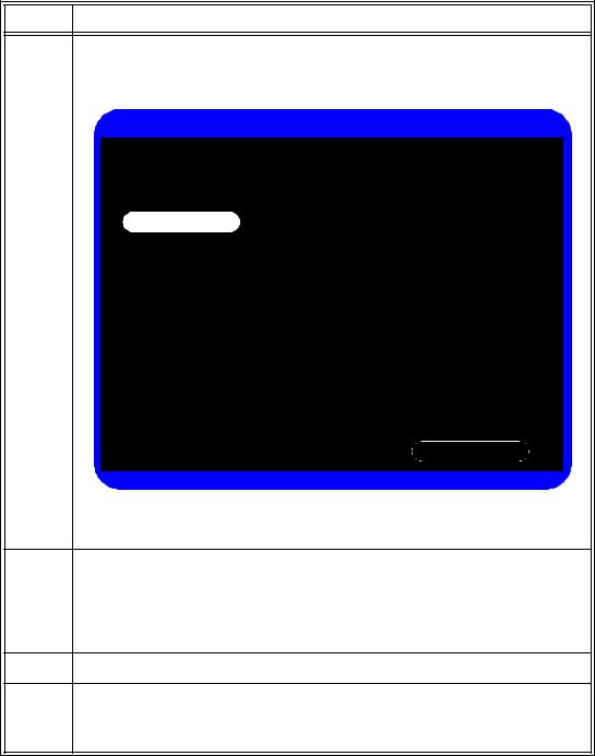
4Select the Upgrade Software button.
The monitor searches for a valid software image on the USB flash drive, and then displays the software image information in the Upgrade Software window.
Upgrade Software
Current Version: |
A.05.24 |
New Version: |
A.05.25 |
Upgrade
WARNING: Battery should be charged before upgrading software. Do no unplug the monitor, remove the USB flash drive, or press any keys after the upgrade process begins. Any user interaction during the upgrade may cause the upgrade to fail and adversely affect monitor performance.
Return
If the monitor cannot find a valid software image, the screen returns to the
System Admin Menu.
5Select the Upgrade Software button to start the upgrade.
The Upgrade in Progress indicator increments while the upgrade is in progress. When the upgrade is complete, the Checking Memory CRC and Upgrade Successful messages appear.
After the software upgrade, the monitor automatically shuts down and restarts.
6Remove the USB flash drive.
7Before placing the monitor back in service, perform the following:
•Power-on self test. See “Power-On Self Test” on page 3-13.
•Verify that your system settings are as expected.
Performance Verification Testing
3-10 SureSigns VS4 Service Guide
Loading...