


 Loading...
SureSigns VS2
Vital Signs Monitor
I N S T R U C T I O N S F O R U S E
Release A.00
English

Notice
Proprietary Information
This document contains proprietary information, which is protected by copyright.
Copyright
Copyright © 2008 Koninklijke Philips Electronics N.V.
All Rights Reserved
Manufacturer
Philips Medical Systems 3000 Minuteman Road Andover, MA 01810 (978) 687-1501
Document Number 4535 640 82491
Warranty Disclaimer
The information contained in this document is subject to change without notice. Philips Medical Systems makes no warranty of any kind with regard to this material, including, but not limited to, the implied warranties or merchantability and fitness for a particular purpose. Philips Medical Systems shall not be liable for errors contained herein or for incidental or consequential damages in connection with the furnishing, performance, or use of this material.
ii SureSigns VS2 Instructions for Use

Printing History
New editions of this document incorporate all material updated since the previous edition. Update packages may be issued between editions and contain replacement and additional pages to be merged by a revision date at the bottom of the page. Pages that are rearranged due to changes on a previous page are not considered revised.
The documentation printing date and part number indicate its current edition. The printing date changes when a new edition is printed. (Minor corrections and updates that are incorporated at reprint do not cause the date to change.) The document part number changes when extensive technical changes are incorporated.
First Edition. . . . . . . . . . . . . . . . . . . . . . . . . . . . . . . . .December 2008
SureSigns VS2 Instructions for Use iii

Conventions
The manual uses the following conventions for Notes, Cautions, and Warnings.
Note — A Note calls attention to an important point in the text.
Caution |
A Caution calls attention to a condition or possible situation that could |
|
damage or destroy the product or the user’s work. |
|
|
Warning |
A Warning calls attention to a condition or possible situation that could |
|
cause injury to the user and/or patient. |
|
|
|
|
iv SureSigns VS2 Instructions for Use

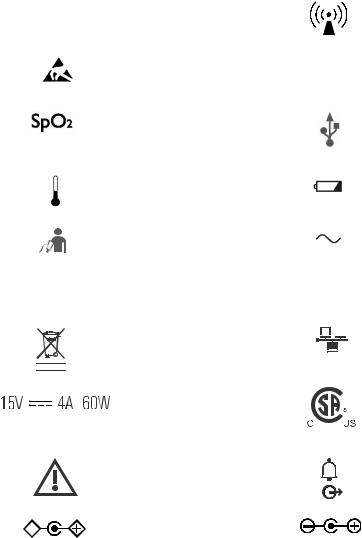
Explanation of Symbols
The following symbols appear on the SureSigns VS2, the external power supply, and the packaging.
Symbol |
Description |
Symbol |
Description |
|
New Patient key |
|
Alarm Silence key |
|
Print key |
|
NBP key |
|
System Menu key |
|
Main Screen key |
|
Display Mode key |
|
On/Standby key |
|
CE marking |
|
Serial number |
0123 |
|
|
|
Rx Only |
Prescription Use Only (US |
|
Batch code |
|
Federal Law) |
|
|
|
Humidity |
|
Date of manufacture |
|
Fragile, handle with care |
|
Keep out of sun |
|
Keep dry |
|
Keep upright |
SureSigns VS2 Instructions for Use v
Symbol |
Description |
Symbol |
Description |
|||||||||||||||||||||||
|
|
|
|
|
|
|
|
|
|
|
|
|
|
|
|
|
|
|
|
|
|
|
|
|
|
|
|
|
|
|
|
|
|
|
|
|
Catalog number |
|
|
|
|
|
|
|
|
|
|
|
|
|
|
|
RF Interference |
|
|
REF |
|
|
|
|
|
|
|
|
|
|
|
|
|
|
|
|
||||||||
|
|
|
|
|
|
|
|
|
|
|
|
|
|
|
|
|
|
|
|
|||||||
|
|
|
|
|
|
|
|
|
|
|
|
|
|
|
|
|
|
|
|
|
|
|
|
|
|
|
|
|
|
|
|
|
|
|
|
|
Electrostatic sensitive |
|
|
|
|
|
|
|
|
|
|
|
|
|
|
|
Sterile |
|
|
|
|
|
|
|
|
|
|
device handling |
|
STERILE |
|
|
||||||||||||
|
|
|
|
|
|
|
|
|
|
|
|
|
|
|
|
|
|
|
|
|
|
|
|
|
|
|
|
|
|
|
|
|
|
|
|
|
SpO2 connector |
|
|
|
|
|
|
|
|
|
|
|
|
|
|
|
USB port |
|
|
|
|
|
|
|
|
|
|
|
|
|
|
|
|
|
|
|
|
|
|
|
|
|
|
|
|
|
|
|
|
|
|
|
|
|
Temperature connector |
|
|
|
|
|
|
|
|
|
|
|
|
|
|
|
Charging LED |
|
|
|
|
|
|
|
|
|
|
|
|
|
|
|
|
|
|
|
|
|
|
|
|
|
||
|
|
|
|
|
|
|
|
|
|
|
|
|
|
|
|
|
|
|
|
|
|
|
|
|
|
|
|
|
|
|
|
|
|
|
|
|
|
|
|
|
|
|
|
|
|
|
|
|
|
|
|
|
|
|
|
|
|
|
|
|
|
|
|
NBP connector |
|
|
|
|
|
|
|
|
|
|
|
|
|
|
|
AC power LED |
|
|
|
|
|
|
|
|
|
|
|
|
|
|
|
|
|
|
|
|
|
|
|
|
|
||
|
|
|
|
|
|
|
|
|
|
|
|
|
|
|
|
|
|
|
|
|
|
|
|
|
|
|
|
|
|
|
|
|
|
|
|
|
|
|
|
|
|
|
|
|
|
|
|
|
|
|
|
|
|
ICES-001 |
Canadian ISM |
|
|
|
|
|
|
|
|
|
|
|
|
|
|
|
Option number |
|||||||||
|
|
OPT |
|
|
||||||||||||||||||||||
requirement |
|
|
|
|
||||||||||||||||||||||
|
|
|
|
|
|
|
|
|
|
|
|
|
|
|
|
|
|
|
|
|
|
|
|
|
|
|
|
|
|
|
|
|
|
|
|
|
Compliance with |
|
|
|
|
|
|
|
|
|
|
|
|
|
|
|
Ethernet port |
|
|
|
|
|
|
|
|
|
|
WEEE standard |
|
|
|
|
|
|
|
|
|
|
|
|
|
|
|
|
|
|
|
|
|
|
|
|
|
|
|
|
|
|
|
|
|
|
|
|
|
|
|
|
|
|
|
|
|
|
|
|
|
|
|
|
|
|
|
|
|
|
|
|
|
|
|
|
|
|
|
|
|
|
|
|
|
|
|
|
|
|
|
|
|
|
|
|
|
|
|
|
|
|
|
|
|
|
|
|
|
|
|
|
|
|
|
|
|
|
|
|
|
|
|
|
|
|
|
|
|
|
|
|
|
|
|
|
|
|
|
|
|
|
|
|
|
|
|
|
|
|
|
|
|
|
|
|
|
|
|
|
|
|
|
|
|
|
|
|
|
|
|
|
|
|
|
|
|
|
|
|
|
|
|
|
|
|
|
|
|
|
|
|
|
|
|
|
|
|
|
|
|
|
|
|
|
|
|
|
|
|
|
|
|
|
|
|
|
|
|
|
|
|
|
|
|
|
|
Power label |
|
|
|
|
|
|
|
|
|
|
|
|
|
|
|
CSA mark |
|
|
|
|
|
|
|
|
|
|
|
|
|
|
|
|
|
|
|
|
|
|
|
|
|
|
|
|
|
|
|
|
|
|
|
|
|
|
|
|
|
|
|
|
|
|
|
|
|
|
|
|
|
|
|
|
|
|
|
|
|
|
|
|
|
|
|
|
|
|
|
|
|
|
|
|
|
|
|
|
|
|
|
|
|
|
|
|
|
|
|
Caution, consult |
|
|
|
|
|
|
|
|
|
|
|
|
|
|
|
Nurse call connector |
|
|
|
|
|
|
|
|
|
|
accompanying |
|
|
|
|
|
|
|
|
|
|
|
|
|
|
|
|
|
|
|
|
|
|
|
|
|
|
documents |
|
|
|
|
|
|
|
|
|
|
|
|
|
|
|
|
|
|
|
|
|
|
|
|
|
|
|
|
|
|
|
|
|
|
|
|
|
|
|
|
|
|
|
|
|
|
|
|
|
|
|
|
|
Polarity of DC power |
|
|
|
|
|
|
|
|
|
|
|
|
|
|
|
Polarity of DC power |
|
|
|
|
|
|
|
|
|
|
connector (appears on |
|
|
|
|
|
|
|
|
|
|
|
|
|
|
|
connector (appears on |
|
|
|
|
|
|
|
|
|
|
VS2 monitor) |
|
|
|
|
|
|
|
|
|
|
|
|
|
|
|
External Power Supply) |
|
|
|
|
|
|
|
|
|
|
|
|
|
|
|
|
|
|
|
|
|
|
|
|
|
|
|
vi SureSigns VS2 Instructions for Use

Symbol |
Description |
|
Symbol |
Description |
||
|
|
|
|
|
|
|
|
UL Recognized |
|
|
|
|
VDE Verification |
|
Component |
|
|
|
|
|
|
|
|
|
|
|
|
|
PSE marking |
|
|
|
|
FCC mark - USA |
|
|
|
|
|
|
|
|
Defibrillator Proof |
|
|
|
|
Indoor use only |
|
|
|
|
|
|
|
|
|
|
|
|
|
|
|
Class II Equipment |
|
|
|
|
Earth, ground |
|
|
|
|
|
|
|
|
EUFP (Environmentally- |
|
|
|
|
|
|
friendly use period |
- |
|
|
|
|
|
China) |
|
|
|
|
|
|
|
|
|
|
|
|
SureSigns VS2 Instructions for Use vii

Regulatory and Safety Specifications
Declaration
 0123
0123
The VS2 monitor is a Class IIb device and complies with the requirements of the Council Directive 93/42/EEC of 14 June 1993 concerning medical devices and carries CE-marking accordingly.
Authorized EU Representative
Philips Medizin Systeme Böblingen GmbH
Hewlett-Packard Str. 2
71034 Böblingen
Germany
Rx Only
Caution |
United States Federal Law restricts this device to sale by or on the order of |
|
a physician. |
|
|
viii SureSigns VS2 Instructions for Use

Contents
1. Overview
Before You Begin. . . . . . . . . . . . . . . . . . . . . . . . . . . . . . . . . . . . . . . . . . . . . . . . . . . . . . . . . . . . . 1-1 About the SureSigns VS2 . . . . . . . . . . . . . . . . . . . . . . . . . . . . . . . . . . . . . . . . . . . . . . . . . . . . . . 1-1 Indications for Use . . . . . . . . . . . . . . . . . . . . . . . . . . . . . . . . . . . . . . . . . . . . . . . . . . . . . . . . . . . 1-2 Intended Use . . . . . . . . . . . . . . . . . . . . . . . . . . . . . . . . . . . . . . . . . . . . . . . . . . . . . . . . . . . . . . . . 1-2 SureSigns VS2 Monitor Configurations . . . . . . . . . . . . . . . . . . . . . . . . . . . . . . . . . . . . . . . . . . 1-3
2. Basic Operation
The Front Panel. . . . . . . . . . . . . . . . . . . . . . . . . . . . . . . . . . . . . . . . . . . . . . . . . . . . . . . . . . . . . . 2-1 The Rear Panel . . . . . . . . . . . . . . . . . . . . . . . . . . . . . . . . . . . . . . . . . . . . . . . . . . . . . . . . . . . . . . 2-3 Setting up the Monitor . . . . . . . . . . . . . . . . . . . . . . . . . . . . . . . . . . . . . . . . . . . . . . . . . . . . . . . . 2-4
Powering Up . . . . . . . . . . . . . . . . . . . . . . . . . . . . . . . . . . . . . . . . . . . . . . . . . . . . . . . . . . . . . 2-4 Charging the Battery . . . . . . . . . . . . . . . . . . . . . . . . . . . . . . . . . . . . . . . . . . . . . . . . . . . . . . . 2-5 Changing the System Date and Time. . . . . . . . . . . . . . . . . . . . . . . . . . . . . . . . . . . . . . . . . . . 2-6 On/Standby Mode . . . . . . . . . . . . . . . . . . . . . . . . . . . . . . . . . . . . . . . . . . . . . . . . . . . . . . . . . 2-7 Deep Sleep Mode. . . . . . . . . . . . . . . . . . . . . . . . . . . . . . . . . . . . . . . . . . . . . . . . . . . . . . . . . . 2-7
Mounting . . . . . . . . . . . . . . . . . . . . . . . . . . . . . . . . . . . . . . . . . . . . . . . . . . . . . . . . . . . . . . . . . . . 2-7 Main Screen Display . . . . . . . . . . . . . . . . . . . . . . . . . . . . . . . . . . . . . . . . . . . . . . . . . . . . . . . . . . 2-8
Display Modes . . . . . . . . . . . . . . . . . . . . . . . . . . . . . . . . . . . . . . . . . . . . . . . . . . . . . . . . . . . . 2-9 Tool Tips . . . . . . . . . . . . . . . . . . . . . . . . . . . . . . . . . . . . . . . . . . . . . . . . . . . . . . . . . . . . . . . 2-10
Changing System Settings . . . . . . . . . . . . . . . . . . . . . . . . . . . . . . . . . . . . . . . . . . . . . . . . . . . . 2-11 Networked Monitors . . . . . . . . . . . . . . . . . . . . . . . . . . . . . . . . . . . . . . . . . . . . . . . . . . . . . . . . . 2-13 Using the Monitor Safely . . . . . . . . . . . . . . . . . . . . . . . . . . . . . . . . . . . . . . . . . . . . . . . . . . . . . 2-13
3. Creating a New Patient Record
Patient ID Overview . . . . . . . . . . . . . . . . . . . . . . . . . . . . . . . . . . . . . . . . . . . . . . . . . . . . . . . . . . 3-3
Primary Patient ID . . . . . . . . . . . . . . . . . . . . . . . . . . . . . . . . . . . . . . . . . . . . . . . . . . . . . . . . . 3-4
Saving Measurements With a Patient ID . . . . . . . . . . . . . . . . . . . . . . . . . . . . . . . . . . . . . . . . . 3-4
Saving Measurements Without a Patient ID . . . . . . . . . . . . . . . . . . . . . . . . . . . . . . . . . . . . . . 3-7
Using the Bar Code Scanner . . . . . . . . . . . . . . . . . . . . . . . . . . . . . . . . . . . . . . . . . . . . . . . . . . . 3-9
Viewing Records in the Patient Records Table . . . . . . . . . . . . . . . . . . . . . . . . . . . . . . . . . . . 3-10
Selecting an Existing Patient ID. . . . . . . . . . . . . . . . . . . . . . . . . . . . . . . . . . . . . . . . . . . . . . . . 3-12
Editing a Patient Record. . . . . . . . . . . . . . . . . . . . . . . . . . . . . . . . . . . . . . . . . . . . . . . . . . . . . . 3-14
Deleting Patient Records . . . . . . . . . . . . . . . . . . . . . . . . . . . . . . . . . . . . . . . . . . . . . . . . . . . . . 3-15
Deleting Specific Patient Records . . . . . . . . . . . . . . . . . . . . . . . . . . . . . . . . . . . . . . . . . . . . 3-16
Deleting All Patient Records . . . . . . . . . . . . . . . . . . . . . . . . . . . . . . . . . . . . . . . . . . . . . . . . 3-17
Contents-i
4. Alarms
Visual Alarms . . . . . . . . . . . . . . . . . . . . . . . . . . . . . . . . . . . . . . . . . . . . . . . . . . . . . . . . . . . . . . . 4-1
Flashing Numeric Values. . . . . . . . . . . . . . . . . . . . . . . . . . . . . . . . . . . . . . . . . . . . . . . . . . . . 4-2
Alarm Messages. . . . . . . . . . . . . . . . . . . . . . . . . . . . . . . . . . . . . . . . . . . . . . . . . . . . . . . . . . . 4-2
Alarm Icons . . . . . . . . . . . . . . . . . . . . . . . . . . . . . . . . . . . . . . . . . . . . . . . . . . . . . . . . . . . . . . 4-3
Audible Alarms . . . . . . . . . . . . . . . . . . . . . . . . . . . . . . . . . . . . . . . . . . . . . . . . . . . . . . . . . . . . . . 4-4
Latched and Non-Latched Alarms . . . . . . . . . . . . . . . . . . . . . . . . . . . . . . . . . . . . . . . . . . . . . . 4-5
Changing Alarm Limits . . . . . . . . . . . . . . . . . . . . . . . . . . . . . . . . . . . . . . . . . . . . . . . . . . . . . . . 4-6
Changing Individual Alarm Limits . . . . . . . . . . . . . . . . . . . . . . . . . . . . . . . . . . . . . . . . . . . . 4-7
Changing Alarm Limits in the Alarm Limits Menu . . . . . . . . . . . . . . . . . . . . . . . . . . . . . . . 4-8
Setting System Alarm Options . . . . . . . . . . . . . . . . . . . . . . . . . . . . . . . . . . . . . . . . . . . . . . . . . . 4-9
Enabling Print on Alarm . . . . . . . . . . . . . . . . . . . . . . . . . . . . . . . . . . . . . . . . . . . . . . . . . . . . 4-9
Showing or Hiding Current Alarm Limits . . . . . . . . . . . . . . . . . . . . . . . . . . . . . . . . . . . . . . 4-10
Adjusting the Alarm Volume. . . . . . . . . . . . . . . . . . . . . . . . . . . . . . . . . . . . . . . . . . . . . . . . 4-11
Restoring Default Alarm Settings . . . . . . . . . . . . . . . . . . . . . . . . . . . . . . . . . . . . . . . . . . . . 4-12
Silencing Alarms . . . . . . . . . . . . . . . . . . . . . . . . . . . . . . . . . . . . . . . . . . . . . . . . . . . . . . . . . . . . 4-13
Audio Pause Mode . . . . . . . . . . . . . . . . . . . . . . . . . . . . . . . . . . . . . . . . . . . . . . . . . . . . . . . . 4-13
Audio Off Mode. . . . . . . . . . . . . . . . . . . . . . . . . . . . . . . . . . . . . . . . . . . . . . . . . . . . . . . . . . 4-14
Acknowledging Technical Alarms. . . . . . . . . . . . . . . . . . . . . . . . . . . . . . . . . . . . . . . . . . . . 4-15
Testing Alarms. . . . . . . . . . . . . . . . . . . . . . . . . . . . . . . . . . . . . . . . . . . . . . . . . . . . . . . . . . . . . . 4-16
Nurse Call System Alarms . . . . . . . . . . . . . . . . . . . . . . . . . . . . . . . . . . . . . . . . . . . . . . . . . . . . 4-17
Alarms Safety Information. . . . . . . . . . . . . . . . . . . . . . . . . . . . . . . . . . . . . . . . . . . . . . . . . . . . 4-17
5. Monitoring SpO2
Selecting an SpO2 Sensor . . . . . . . . . . . . . . . . . . . . . . . . . . . . . . . . . . . . . . . . . . . . . . . . . . . . . . 5-1
Connecting SpO2 Cables. . . . . . . . . . . . . . . . . . . . . . . . . . . . . . . . . . . . . . . . . . . . . . . . . . . . . . . 5-2
The SpO2 Numeric Pane. . . . . . . . . . . . . . . . . . . . . . . . . . . . . . . . . . . . . . . . . . . . . . . . . . . . . . . 5-3
Changing SpO2 Settings . . . . . . . . . . . . . . . . . . . . . . . . . . . . . . . . . . . . . . . . . . . . . . . . . . . . . . . 5-3
Changing the SpO2 Response Mode . . . . . . . . . . . . . . . . . . . . . . . . . . . . . . . . . . . . . . . . . . . 5-4
Changing the SpO2 Alarm Limits . . . . . . . . . . . . . . . . . . . . . . . . . . . . . . . . . . . . . . . . . . . . . 5-5
Desaturation Alarm (Desat) . . . . . . . . . . . . . . . . . . . . . . . . . . . . . . . . . . . . . . . . . . . . . . . . . . . . 5-5
SpO2 Safety Information . . . . . . . . . . . . . . . . . . . . . . . . . . . . . . . . . . . . . . . . . . . . . . . . . . . . . . 5-6
6. Monitoring NBP
Selecting an NBP Cuff. . . . . . . . . . . . . . . . . . . . . . . . . . . . . . . . . . . . . . . . . . . . . . . . . . . . . . . . . 6-1
Connecting the Cuff and Hose . . . . . . . . . . . . . . . . . . . . . . . . . . . . . . . . . . . . . . . . . . . . . . . . . . 6-2
NBP Numeric Panes . . . . . . . . . . . . . . . . . . . . . . . . . . . . . . . . . . . . . . . . . . . . . . . . . . . . . . . . . . 6-3
Changing NBP Settings. . . . . . . . . . . . . . . . . . . . . . . . . . . . . . . . . . . . . . . . . . . . . . . . . . . . . . . . 6-4
Enabling Auto Print NBP. . . . . . . . . . . . . . . . . . . . . . . . . . . . . . . . . . . . . . . . . . . . . . . . . . . . 6-5
Changing the NBP Alarm Limits. . . . . . . . . . . . . . . . . . . . . . . . . . . . . . . . . . . . . . . . . . . . . . 6-6
Contents-ii
Configuring the Initial Inflation Pressure . . . . . . . . . . . . . . . . . . . . . . . . . . . . . . . . . . . . . . . .6-7
Changing the NBP Units of Measurement . . . . . . . . . . . . . . . . . . . . . . . . . . . . . . . . . . . . . . .6-8
Stopping an NBP Measurement . . . . . . . . . . . . . . . . . . . . . . . . . . . . . . . . . . . . . . . . . . . . . . . . .6-8
NBP Safety Information . . . . . . . . . . . . . . . . . . . . . . . . . . . . . . . . . . . . . . . . . . . . . . . . . . . . . . .6-9
7. Monitoring Temperature
Connecting the Temperature Probe. . . . . . . . . . . . . . . . . . . . . . . . . . . . . . . . . . . . . . . . . . . . . .7-1
The Temperature Pane . . . . . . . . . . . . . . . . . . . . . . . . . . . . . . . . . . . . . . . . . . . . . . . . . . . . . . . .7-2
Taking a Temperature Measurement . . . . . . . . . . . . . . . . . . . . . . . . . . . . . . . . . . . . . . . . . . . .7-2
Changing Temperature Settings. . . . . . . . . . . . . . . . . . . . . . . . . . . . . . . . . . . . . . . . . . . . . . . . .7-3
Changing the Temperature Mode . . . . . . . . . . . . . . . . . . . . . . . . . . . . . . . . . . . . . . . . . . . . . .7-4
Changing the Probe Site . . . . . . . . . . . . . . . . . . . . . . . . . . . . . . . . . . . . . . . . . . . . . . . . . . . . .7-6
Changing the Temperature Alarm Limits. . . . . . . . . . . . . . . . . . . . . . . . . . . . . . . . . . . . . . . .7-7
Changing the Temperature Units of Measurement. . . . . . . . . . . . . . . . . . . . . . . . . . . . . . . . .7-8
Verifying the Temperature Accuracy . . . . . . . . . . . . . . . . . . . . . . . . . . . . . . . . . . . . . . . . . . . .7-8
Temperature Safety Information . . . . . . . . . . . . . . . . . . . . . . . . . . . . . . . . . . . . . . . . . . . . . . .7-10
8. Monitoring Heart Rate
Changing Heart Rate Settings . . . . . . . . . . . . . . . . . . . . . . . . . . . . . . . . . . . . . . . . . . . . . . . . . .8-1
Changing the Heart Rate Alarm Limits . . . . . . . . . . . . . . . . . . . . . . . . . . . . . . . . . . . . . . . . .8-2
Changing the Heart Rate Source. . . . . . . . . . . . . . . . . . . . . . . . . . . . . . . . . . . . . . . . . . . . . . .8-3
Adjusting the Heart Rate Volume. . . . . . . . . . . . . . . . . . . . . . . . . . . . . . . . . . . . . . . . . . . . . .8-4
9. Using the Recorder
Loading the Recorder Paper. . . . . . . . . . . . . . . . . . . . . . . . . . . . . . . . . . . . . . . . . . . . . . . . . . . .9-1 Printing One Patient Record. . . . . . . . . . . . . . . . . . . . . . . . . . . . . . . . . . . . . . . . . . . . . . . . . . . .9-3 Printing Multiple Patient Records . . . . . . . . . . . . . . . . . . . . . . . . . . . . . . . . . . . . . . . . . . . . . . .9-4 Exporting Patient Records . . . . . . . . . . . . . . . . . . . . . . . . . . . . . . . . . . . . . . . . . . . . . . . . . . . . .9-5 Enabling Print on Alarm. . . . . . . . . . . . . . . . . . . . . . . . . . . . . . . . . . . . . . . . . . . . . . . . . . . . . . .9-6 Enabling Auto Print NBP . . . . . . . . . . . . . . . . . . . . . . . . . . . . . . . . . . . . . . . . . . . . . . . . . . . . . .9-6
10. Care and Cleaning
General Guidelines. . . . . . . . . . . . . . . . . . . . . . . . . . . . . . . . . . . . . . . . . . . . . . . . . . . . . . . . . . .10-2
Cleaning and Disinfecting the Monitor . . . . . . . . . . . . . . . . . . . . . . . . . . . . . . . . . . . . . . . . . .10-3
Cleaning and Disinfecting the Cables and External Power Supply . . . . . . . . . . . . . . . . . . .10-4
11. Accessories List
SpO2 Accessories . . . . . . . . . . . . . . . . . . . . . . . . . . . . . . . . . . . . . . . . . . . . . . . . . . . . . . . . . . . .11-2
NBP Accessories . . . . . . . . . . . . . . . . . . . . . . . . . . . . . . . . . . . . . . . . . . . . . . . . . . . . . . . . . . . . .11-5
Temperature Accessories . . . . . . . . . . . . . . . . . . . . . . . . . . . . . . . . . . . . . . . . . . . . . . . . . . . . .11-9
Miscellaneous Accessories . . . . . . . . . . . . . . . . . . . . . . . . . . . . . . . . . . . . . . . . . . . . . . . . . . . . .11-9
Contents-iii
12. Specifications
General Specifications. . . . . . . . . . . . . . . . . . . . . . . . . . . . . . . . . . . . . . . . . . . . . . . . . . . . . . . . 12-1
Safety Standards . . . . . . . . . . . . . . . . . . . . . . . . . . . . . . . . . . . . . . . . . . . . . . . . . . . . . . . . . . . . 12-2
Electrical Specifications . . . . . . . . . . . . . . . . . . . . . . . . . . . . . . . . . . . . . . . . . . . . . . . . . . . . . . 12-2
Environmental Specifications. . . . . . . . . . . . . . . . . . . . . . . . . . . . . . . . . . . . . . . . . . . . . . . . . . 12-3
NBP Specifications . . . . . . . . . . . . . . . . . . . . . . . . . . . . . . . . . . . . . . . . . . . . . . . . . . . . . . . . . . 12-4
Temperature Specifications . . . . . . . . . . . . . . . . . . . . . . . . . . . . . . . . . . . . . . . . . . . . . . . . . . . 12-5
SpO2 Specifications . . . . . . . . . . . . . . . . . . . . . . . . . . . . . . . . . . . . . . . . . . . . . . . . . . . . . . . . . . 12-5
Recorder Specifications . . . . . . . . . . . . . . . . . . . . . . . . . . . . . . . . . . . . . . . . . . . . . . . . . . . . . . 12-7
Bar Code Scanner Specifications . . . . . . . . . . . . . . . . . . . . . . . . . . . . . . . . . . . . . . . . . . . . . . . 12-8
Interface Specifications. . . . . . . . . . . . . . . . . . . . . . . . . . . . . . . . . . . . . . . . . . . . . . . . . . . . . . . 12-8
A. Alarm Specifications
Physiological Alarms. . . . . . . . . . . . . . . . . . . . . . . . . . . . . . . . . . . . . . . . . . . . . . . . . . . . . . . . . A-1
Technical Alarms. . . . . . . . . . . . . . . . . . . . . . . . . . . . . . . . . . . . . . . . . . . . . . . . . . . . . . . . . . . . A-2
Factory Default Alarm Limits and Alarm Ranges. . . . . . . . . . . . . . . . . . . . . . . . . . . . . . . . . A-5
B. Electromagnetic Compatibility
Contents-iv

1 Overview
Before You Begin
This manual describes how to operate the SureSigns™ VS2 vital signs monitor.
For information on setting up the monitor, see the SureSigns VS2 Setup Guide, which describes how to install the battery, power up the monitor, and configure some of the system settings before using the monitor.
About the SureSigns VS2
This chapter provides a brief overview of the SureSigns VS2 monitor.
Overview |
|
SureSigns VS2 Instructions for Use |
1-1 |

Indications for Use
Note — Your monitor may look different from the monitors pictured in this manual if you purchased a different model.
The SureSigns VS2 is a vital signs monitor that can measure blood pressure, pulse rate, oxygen saturation (SpO2), and temperature. Features include:
•Adult, pediatric, and neonatal capability
•Lithium ion battery
•Stores up to 100 patient records
•Optional recorder
•Optional roll stand or wall mount
•Optional bar code scanner for Patient ID entry
•LAN and serial data export
•Optional wireless network connection
Indications for Use
The SureSigns VS2 vital signs monitor is for use by health care professionals whenever there is a need for monitoring the physiological parameters of patients.
Intended Use
The SureSigns VS2 vital signs monitor is for monitoring, recording and alarming of multiple physiological parameters of adults, pediatrics, and neonates in healthcare environments. Additionally, the monitor is intended for use in transport situations within a healthcare facility.
Overview
1-2 SureSigns VS2 Instructions for Use

SureSigns VS2 Monitor Configurations
SureSigns VS2 Monitor Configurations
The SureSigns VS2 is available in several configurations. The following table lists the parameters and features available in each model.
Configuration |
|
Measurement Parameters and Features |
|||
Number |
|
|
|
|
|
NBP |
|
SpO2 |
Temp |
Recorder |
|
|
|
||||
863079 |
Yes |
|
No |
No |
No |
|
|
|
|
|
|
863080 |
Yes |
|
Yes |
No |
No |
|
|
|
|
|
|
863081 |
Yes |
|
Yes |
Yes |
No |
|
|
|
|
|
|
863082 |
Yes |
|
Yes |
Yes |
Yes |
|
|
|
|
|
|
Overview |
|
SureSigns VS2 Instructions for Use |
1-3 |
SureSigns VS2 Monitor Configurations
Overview
1-4 SureSigns VS2 Instructions for Use

2 Basic Operation
This chapter describes how to begin using the SureSigns VS2 monitor.
For information on setting up and configuring the monitor, see the SureSigns
VS2 Setup Guide.
The Front Panel
All function keys and LEDs are on the monitor’s front panel. The following illustration and table describe these controls.
New Patient key |
|
|
|
|
Alarm Silence key |
|
Print key |
|
|
|
|
NBP key |
|
|
|
|
|
|
|
Navigation wheel |
System Menu key |
|
|
|
|
Main Screen key |
|
Display Mode key |
|
|
|
|
On/Standby key |
|
Charging LED |
Power LED |
Basic Operation |
|
SureSigns VS2 Instructions for Use |
2-1 |

The Front Panel
Control |
Icon |
Description |
||
|
|
|
|
|
|
|
|
|
|
New Patient |
|
|
Press to open the New Patient Menu. |
|
key |
|
|
|
|
|
|
|
|
|
Print key |
|
|
Press to print the last saved patient record. If Patient Records are |
|
|
|
|
displayed, press to print the patient record that is currently highlighted. |
|
|
|
|
|
|
System Menu |
|
|
Press to open the System Menu. |
|
key |
|
|
|
|
|
|
|
|
|
Display Mode |
|
|
Press to switch between the two display modes of the main screen: |
|
key |
|
|
• |
Patient Records mode |
|
|
|
||
|
|
|
• |
Vital Signs mode |
|
|
|
|
|
Alarm |
|
|
Press to pause an alarm for a specified period of time. Press twice |
|
Silence key |
|
|
quickly to initiate the Audio Pause period. Press and hold this key for 2 |
|
|
|
|
seconds to initiate Audio Off mode. To turn audio alarms back on, press |
|
|
|
|
the Alarm Silence key. For more information, see Silencing Alarms on |
|
|
|
|
page 4-13. |
|
|
|
|
|
|
NBP key |
|
|
Press to start an NBP measurement. If an NBP measurement is |
|
|
|
|
underway, and you press this key, the measurement stops. |
|
|
|
|
|
|
Navigation |
|
|
Use the navigation wheel to select and change various settings. |
|
wheel |
|
|
|
|
|
|
|
|
|
Main Screen |
|
|
Press to quickly exit from a screen and return to the Vital Signs mode of |
|
key |
|
|
the main monitoring screen. |
|
|
|
|
|
|
On/Standby |
|
|
Press once to turn the monitor on. Press again to enter Standby mode. In |
|
key |
|
|
Standby mode, the display blanks and all monitoring ceases, but the |
|
|
|
|
monitor does not actually turn off. |
|
|
|
|
|
|
Charging |
|
|
Changes color based on the charging status of the battery. For more |
|
LED |
|
|
information, see Charging the Battery on page 2-5. |
|
|
|
|
|
|
Power LED |
|
|
When lit, indicates that the monitor is connected to an AC power source. |
|
|
|
|
|
|
Basic Operation
2-2 SureSigns VS2 Instructions for Use

The Rear Panel
The Rear Panel
The following illustration and table describe the connectors on the back of the monitor.
Ethernet port
USB port
Nurse Call connector
Power connector 
|
|
|
|
|
Connector |
Description |
|
|
|
|
|
|
|
|
|
|
|
|
|
|
|
|
|
|
|
|
|
|
|
Ethernet |
10/100 Base-T Ethernet port. Used for LAN data export. See your system |
|
|
|
|
|
|
port |
administrator for more information. |
|
|
|
|
|
|
|
|
|
|
|
|
|
|
USB port |
Standard USB 1.1, 4-pin connector used for: |
|
|
|
|
|
|
|
• The optional bar code scanner |
|
|
|
|
|
|
|
• Data export through the optional serial interface adapter |
|
|
|
|
|
|
|
• Patient record export |
|
|
|
|
|
|
|
See your system administrator for more information. |
|
|
|
|
|
|
|
|
|
|
|
|
|
|
Nurse call |
3.5 mm phone jack for connection to a nurse call system. |
|
|
|
|
|
|
connector |
|
|
|
|
|
|
|
|
|
Power connector |
Connection for the external power supply. |
||||||
|
|
|
|
|
|
|
|
|
|
|
|
|
|
|
|
|
|
|
|
|
|
|
|
Basic Operation |
|
SureSigns VS2 Instructions for Use |
2-3 |

Setting up the Monitor
Setting up the Monitor
This section describes how to power up the monitor, charge the battery, and change the system date and time.
Powering Up
The monitor operates on AC power or the internal battery. To power up the monitor:
Step
1If not already connected, plug the external power supply into the power connector on the monitor’s rear panel and into an AC power source.
Caution - Use only the Philips-provided power supply (Astec model DPS54-M).
2Ensure that the AC outlet is properly grounded and supplies the specified voltage and frequency (100 - 240 VAC, 50 - 60 Hz).
Note — Within the U.S., a hospital-grade outlet is recommended.
The green power LED on the front panel lights when the AC power source is connected. Also, the battery indicator on the front panel indicates the current status of the battery. See the next section, Charging
the Battery, for more information.
3 |
|
Press the On/Standby key. |
|
 The monitor powers up and performs a self-test. On/Standby key During this self-test, the monitor also tests the
speaker; listen for an audible tone to confirm that the speaker is working properly.
You may also be prompted to change the system date and time the first time you power up the system. See Changing the System Date and Time on page 2-6 for more information.
Basic Operation
2-4 SureSigns VS2 Instructions for Use
Setting up the Monitor
Charging the Battery
Any time the monitor is connected to AC power, the battery is being charged. When you first receive the monitor, the battery charge may be
Charging LED low. You should connect the monitor to an AC power source before using it on battery power alone.
Note — To ensure that the battery is sufficiently charged, keep the monitor plugged in to AC power when it is not in use.
The Charging LED on the front panel provides the charging status of the battery. The color of the LED tells you how much charge remains on the battery:
•Green: The battery is at least 90% charged.
•Flashing Green: More than 30% charge, but less than 90%.
•Yellow: More than 21% charge, but less than 30%.
•Flashing Yellow: Less than 21% charge.
The battery status pane on the bottom of the LCD screen also indicates battery status.
Battery Status
If the monitor is connected to AC power, and the external power supply is then disconnected, the monitor automatically resorts to battery power, if the battery is sufficiently charged. All alarm settings and patient
records are preserved.
Warning Dispose of used batteries in an environmentally responsible manner. Do not dispose of the battery in normal waste containers. Consult your hospital administrator to find out about local arrangements.
Basic Operation |
|
SureSigns VS2 Instructions for Use |
2-5 |

Setting up the Monitor
Changing the System Date and Time
Use the following procedure to change the system date and time. If the Date/Time Menu is already open, skip to step 3.
Caution When you change the date or time, all patient data is deleted.
|
|
|
|
|
Step |
|
|
|
|
|
|
|
1 |
Rotate the navigation wheel until the date and time pane is highlighted. |
|
|
|
The date and time pane is in the lower right corner of the screen |
|
|
|
display. |
|
|
|
|
|
|
2 |
Press the wheel. |
|
|
|
The Date/Time Menu appears. |
|
|
|
|
|
|
3 |
Rotate the wheel until the value you want to change is highlighted. |
|
|
|
|
|
|
4 |
Press the wheel and rotate it until the desired value appears. |
|
|
|
|
|
|
5 |
Press the wheel again to save the new value. |
|
|
|
|
|
|
6 |
Repeat steps 3 to 5 to change other values in the menu. |
|
|
|
|
|
|
7 |
Rotate the wheel until the Apply button is selected and press the wheel |
|
|
|
to save your changes and close the menu. |
|
|
|
|
|
|
|
|
|
You can change the date format (mm/dd/yyyy or dd/mm/yyyy) and you can hide the time display using options in the System Menu. For details, see Changing System Settings on page 2-11.
Note — The system clock does not adjust for daylight savings time. You must manually change the time.
Basic Operation
2-6 SureSigns VS2 Instructions for Use

Mounting
On/Standby Mode
If you press the On/Standby key while the monitor is On, the monitor goes into Standby mode and the following occurs:
•The display goes blank.
•Battery charging continues if the monitor is connected to an AC power source.
•Patient records remain in memory.
•Monitoring stops.
To reduce battery consumption, your system administrator can configure the monitor to automatically go into Standby mode after 5, 10, 15 or 30 minutes of inactivity. Only authorized personnel can change this setting (the Auto Suspend setting) in the password-protected System Admin Menu.
To resume monitoring, press the On/Standby key.
Deep Sleep Mode
The monitor enters Deep Sleep mode when:
•The monitor is not connected to an AC power source and it remains in Standby mode for more than 30 minutes or the battery level drops below 30%.
•The monitor is on, but not connected to an AC power source, and the battery level drops below 12%.
In Deep Sleep mode, the display is blank and the system uses minimal power to maintain the system clock.
To resume normal monitoring, connect the monitor to an AC power source and press the On/Standby key to turn the monitor back On.
Mounting
You can mount the monitor on a roll stand or a wall mount. For information on mounting the monitor, see the Instructions for Use that comes with the hardware.
Basic Operation |
|
SureSigns VS2 Instructions for Use |
2-7 |

Main Screen Display
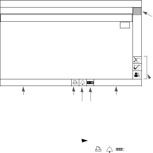
Main Screen Display
Note — The illustrations in this manual show the screens on a fully configured VS2 monitor.
The main screen contains the following basic elements:
•Numeric panes display vital signs measurements and are shown when the display is set to Vital Signs mode.
•The Patient Records Table shows patient records that are saved in the monitor and is shown when the display is set to Patient Records mode. See Display Modes on page 2-9 for more information on display modes.
•The Message area displays short text descriptions of all active alarms. Highpriority alarms pre-empt lower priority alarms. Once the high-priority alarm has been resolved, the low priority alarm message appears. If multiple alarms of the same priority occur at the same time, the alarm messages rotate every 1.5 seconds.
•The Print button is used to open the Print Patient Data menu. In the Print Patient Data menu, you can select the number of records to print or export patient records to a USB drive.
•The Alarms button is used to open the Alarm Limits Menu, where you can set alarm limits. From the Alarm Limits Menu, you can open the Alarm Settings Menu, where you can show or hide alarm limits, set the alarm tone volume, restore default alarm settings, and set the monitor to print on alarm.
•The Battery Status icon shows the current charge of the monitor’s battery.
•The Date/Time pane displays the current date and time. You can hide the time, as described in Changing System Settings on page 2-11.
•The Patient Records buttons are used to view, save, edit, delete, or cancel changes to patient records. See Chapter 3, “Creating a New Patient Record,” for more information.
Basic Operation
2-8 SureSigns VS2 Instructions for Use

Main Screen Display
Display Modes
Press the Display Mode key to switch between the monitor’s two display modes: Vital Signs and Patient Records. By default, the main screen is in
Vital Signs mode and displays vital signs for the current patient.
Display Mode key
Numeric Panes |
Patient Records |
|
buttons |
Adult 0009875433
SYS |
|
|
mmHg |
|
SpO2% |
98 |
|
|
SpO2% |
|||||||||||
90 |
122 |
|
90 |
|
|
|
|
|
||||||||||||
160 |
85 |
|
100 |
|
|
|
|
|
|
|
|
|
|
|
|
|||||
|
|
|
|
|
|
|
|
|
|
|
|
|
|
|
||||||
|
|
|
|
|
|
|
|
|
|
|
|
|
|
|
||||||
DIA |
|
|
|
|
bpm |
80 |
|
|
|
|||||||||||
90 |
|
12050 |
|
|
|
|
|
|
||||||||||||
50 |
|
|
|
|
|
|
|
|||||||||||||
MAP |
98 |
|
|
|
|
ºC |
37.1 |
Oral |
||||||||||||
|
|
|
|
|
|
|
|
|
|
|
|
|
|
|||||||
110 |
|
|
|
|
39.0 |
|
|
|
|
|
|
|
|
|
|
|
|
|||
70 |
|
|
|
|
36.0 |
|
|
|
|
|
|
|
|
|
|
|
|
|||
|
|
|
|
|
|
|
|
|
|
|
|
|
|
|
|
|
|
|
|
|
|
|
|
|
|
|
|
|
|
|
|
|
|
|
|
|
|
06/21/2009 03:31:00 |
|||
|
|
|
|
|
|
|
|
|
|
|
|
|
|
|
|
|
||||
|
|
|
|
|
|
|
|
|
|
|
|
|
|
|
|
|
||||
|
|
|
|
|
|
|
|
|
|
|
|
|
|
|
|
|||||
|
Message |
|
Area |
Print button |
|
|
|
|
|
|
|
|
|
|
|
|
||||
|
|
|
|
|
|
|
|
Date/Time Pane |
||||||||||||
|
|
|
|
Alarms button |
|
|
|
|
|
|
Battery Status icon |
|
|
|||||||
|
|
|
|
|
|
|
|
|
|
|||||||||||
Basic Operation |
|
SureSigns VS2 Instructions for Use |
2-9 |
Main Screen Display
In Patient Records mode, the main screen displays the patient records table. You can display all patient records or all records for a specific patient. When highlighted, the record expands to show vital signs and patient type, as well as the patient name and patient ID, if entered. If you do not enter a patient ID, the text ID Unknown is displayed. You can also edit or delete patient records. See Chapter 3, “Creating a New Patient Record,” for more information on the Patient Records table.
Patient/Type |
|
Date |
Time |
HR |
NBP |
SpO2 |
Temp |
|
0009875433 |
A |
06/21/09 |
03:20:12 |
65SpO2 |
-- / -- (--) |
98 |
36.8 |
Scroll bar |
0007363627 |
A |
06/21/09 |
03:16:44 |
64SpO2 |
-- / -- (--) |
98 |
39.1 |
|
0006352516 |
A |
06/21/09 |
03:12:41 |
72SpO2 |
-- / -- (--) |
99 |
36.9 |
|
0008763842 |
A |
06/21/09 |
03:08:03 |
60SpO2 |
-- / -- (--) |
98 |
37.1 |
|
0006655321 |
A |
06/21/09 |
03:00:43 |
80SpO2 |
-- / -- (--) 99 36.6 |
|
||
0008764332 |
A |
06/21/09 |
02:55:11 |
56 NBP |
111/60 (82) |
97 |
37.2 |
|
0008893376 |
A |
06/21/09 |
02:50:06 |
77SpO2 |
-- / -- (--) |
95 |
37.0 |
|
0008873221 |
A |
06/21/09 |
02:44:32 |
78SpO2 |
-- / -- (--) |
98 |
36.8 |
|
0003323876 |
P |
06/21/09 |
02:40:51 |
75SpO2 |
-- / -- (--) 97 36.9 |
|
||
|
|
|
|
|
06/21/2009 03:31:00 |
Patient |
||
|
|
|
|
|
|
|
|
Records |
Message Area |
Print button |
|
Date/Time Pane |
buttons |
||||
|
|
|||||||
Alarms button Battery Status icon
Tool Tips
When you rotate the navigation wheel to highlight a button in the main screen, a description of the highlighted button pops up, as seen in the following illustration.
Tool Tip pops |
|
|
|
|
|||||||
up for Print |
|
|
|
|
|
|
|
|
|
|
|
|
|
|
|
|
|
|
|
|
|
||
button |
|
|
|
|
|
|
|
|
|
|
|
|
|
|
|
|
|
|
|
|
|
||
|
|
|
|
|
|
|
|
|
|
||
|
|
|
|
|
|
|
|
|
|
|
|
Basic Operation
2-10 SureSigns VS2 Instructions for Use

Changing System Settings
Changing System Settings
System Menu
key
The System Menu contains several system settings and a System Admin button that provides access to the password-protected System Admin Menu.
The System Info button opens a list of monitor-specific information.
To change settings in the System Menu:
Step
1Press the System Menu key on the front panel to open the System Menu.
The System Menu appears. Current settings are displayed.
Basic Operation |
|
SureSigns VS2 Instructions for Use |
2-11 |

Changing System Settings
2Turn the wheel to select one of the following system settings:
•Date Format — You can change the monitor’s date format. Options are mm/dd/yyyy and dd/mm/yyyy.
•Display Time — Use this setting to show or hide the time in the lower right corner of the display.
•Default Patient Type — Select a patient type. Each time you start a new patient, the default patient type is selected and the alarm settings are restored to the default values for the specified patient type.
•Monitor Name— The default monitor name is the monitor serial number. You can use this field to change the default name to something more meaningful. The Monitor Name can be up to 10 characters long.
•System Info button — Use this button to open a list of monitorspecific information, including the monitor’s hardware and software versions.
•System Admin button — Only qualified service personnel can open the System Admin Menu, which is password-protected.
For more information on these settings, see the appropriate sections of this manual.
3Press the Main Screen key on the front panel to close the menu.
Alternative: Rotate the wheel until the Main Screen button is selected and press the wheel.
Basic Operation
2-12 SureSigns VS2 Instructions for Use

Networked Monitors
Networked Monitors
If your monitor is networked, the records in the Patient Records table change from white to green after they have been exported; if the records do not change from white to green, see your system administrator for assistance.
Caution If you are using the optional serial interface adapter to export data and you disconnect the adapter to move the monitor to a different location, make sure the black sheath completely covers the RS-232 connector after you reconnect the cable.
Using the Monitor Safely
All of the patient applied parts on the SureSigns VS2 vital signs monitor are classified as type CF, which specifies their degree of protection against electrical shock. All are rated as defibrillator proof, as indicated by the heart symbol on the side panel.
This monitor is suitable for use in the presence of electrosurgery.
SureSigns VS2 vital signs monitors conform to CISPR 11. SureSigns VS2 vital signs monitors are suitable for use in all establishments except domestic establishments and those directly connected to the public low-voltage power supply network that supplies buildings used for domestic purposes.
Ensure that the monitor is in working condition before clinical use. If the accuracy of any measurement does not seem reasonable, first check the patient’s vital signs by alternative means and then with the monitor to make sure it is working properly. Always verify that the monitor’s settings match your intended selections.
If you connect the monitor to any instrument, verify proper operation before clinical use. Refer to the instrument’s Instructions for Use for full instructions.
Accessory equipment connected to the monitor’s data interface must be certified according to IEC Standard 60950 for data-processing equipment or IEC Standard
Basic Operation |
|
SureSigns VS2 Instructions for Use |
2-13 |

Using the Monitor Safely
60601-1 for electromedical equipment. All combinations of equipment must be in compliance with IEC Standard 60601-1-1 systems requirements.
Anyone who connects additional equipment to the signal input port or signal output port configures a medical system and is therefore responsible to ensure that the system complies with the requirements of system standard IEC Standard 60601-1-1. If in doubt, contact the Philips Customer Care Center or your local Philips representative.
The monitor and its accessories must be tested by qualified service personnel at regular intervals to ensure that performance has not been degraded by aging or environmental conditions. Periodic performance verification tests can be performed, as described in the
SureSigns VS2 Service Guide.
Warning Explosion Hazard. Equipment not suitable for use in the presence of a flammable anaesthetic mixture with air or oxygen or nitrous oxide. Oxygen concentrations must be <25% and partial pressure <27.5 kPa when no other oxidants are present.
Electric shock hazard. Covers should be removed only by qualified service personnel. There are no user-serviceable parts inside.
Do not touch the patient, or table, or instruments during defibrillation.
Measurement accuracy may decrease temporarily while performing electro-surgery or defibrillation. This does not affect patient or equipment safety.
Do not open the monitor or attempt to change the battery. If you suspect a problem with parts within the monitor, contact your biomed or local Philips Representative.
Before you begin monitoring, make sure that the correct patient type is selected. The monitor’s default alarm limits and initial cuff inflation pressures are based on the selected patient type.
Route patient cabling to reduce the possibility of patient entanglement or strangulation.
Do not place the monitor in any position that might cause it to fall on the patient. Do not lift the monitor by the power supply cord or patient connections.
The roll stand basket has a maximum capacity of 8 pounds (3.6 kg). If you place more than 8 pounds (3.6 kg) in the basket, the roll stand may tip.
Do not use the monitor on more than one patient at a time.
To ensure patient electrical isolation, connect only to other equipment that provides patient electrical isolation. Use only unshielded network cables.
Basic Operation
2-14 SureSigns VS2 Instructions for Use
Loading...