


User Manual
SM30
Sound Management System
User Manual
LBB 1280
Philips
Communication &
Security Systems

CONTENTS |
|
page |
|
1 |
Introduction |
|
1 |
2 |
System operation |
|
4 |
3 |
Attention and alarm signals |
|
6 |
4 |
Control centre |
LBB 1280 |
8 |
5 |
Setting up the hardware |
|
11 |
6 |
SM30 call station |
LBB 9568 |
18 |
7 |
Call station input module |
LBB 1283 |
22 |
8 |
Microphone input module |
LBB 1282 |
23 |
9 |
Control input module |
LBB 1284 |
24 |
10 |
Recorded message module |
LBB 1285 |
26 |
11 |
Music input module |
LBB 1286 |
28 |
12 |
Zone relay module |
LBB 1287 |
30 |
13 |
Control relay module |
LBB 1288 |
32 |
14 |
Programming |
|
|
14.1 |
Summary SM30 User Programming |
|
34 |
14.2 |
General |
|
35 |
14.3 |
User programming |
|
35 |
14.4 |
Error messages |
|
44 |
14.5 |
Summary of SM30 Installer programming |
* |
|
14.6 |
Setup programming |
|
* |
14.7 |
Installer programming |
|
* |
15 |
Specifications |
|
45 |
*Installer supplementary sheets

1 INTRODUCTION
The SM30 sound management system provides an ideal solution for public address distribution systems, requiring a compact and flexible set-up with ease of operation. Being controlled by a microprocessor, the system is particularly flexible, specific functions being easily made and changed by non technical personnel. In order to meet differing application needs a variety of plug-in modules are available, and a wide range of system configurations are possible. The total public address distribution system comprises:
■One Control Centre, containing a microprocessor and plug-in modules.
■SM30 Call stations.
■Power amplifiers which feed loudspeakers located in geographical and/or functional zones where people must be reached with background music, announcements, prerecorded messages, and alarm signals.
A maximum of 6 Call Stations may be used, their functions being programmed from a keyboard and display unit built into the Control Centre. The system is designed to handle calls and music simultaneously, so that if a call is made to a particular zone or combination of zones, music playing in other zones will not be interrupted. A system of priorities has been developed to cope with conflict situations, for example a person attempting to make a call when another call is being made by someone with a higher priority, the new call will not be switched through.
Control Centre
At the heart of each SM30 system is the Control Centre. This is a self contained unit, housing the microprocessor which controls SM30, and 12 slots which hold the
plug-in modules.
On the front panel of the Control Centre are programming keys and associated LEDs, an alpha-numeric LCD display, and keys for controlling the functions of the music source inputs. The programming keys enable the installer to program SM30 to suit the overall system configuration, and the user’s specific needs. To allow the operator to control the music sources, four Music Function Keys are provided on the front panel.
These keys allow the operator to select the music source; alter the music volume level up or down; and mute the music signal.
Programming
The displays and the programming menus are presented in the selected language. In the normal ‘run’ mode of the system, the LCD display indicates the name of the current music source (e.g. “TUNER”, or “MUSIC OFF”), plus the current music volume level. In the ‘programming’ mode, the display will enable the installer/user to see:
■Program selections while scrolling through the programming menus.
■Function selections within a program.
■The number of the current Call Station; Function Key; Microphone; Control Inputs; etc., being programmed.
■Call priority status.
■Attention or Alarm signal number.
■Pre-recorded message number.
■Loudspeaker Zone call; Control Relay; and music routing.
■Alternative Function Key functions.
■Alternative Music Input text.
■Current program status (e.g. CLEARING MEMORY PLEASE WAIT).
■‘Error’ indications.
■Language selection.
■Alarm interruption.
■Power-on delay.
1

SM30 plug-in modules
All of the interconnections between individual modules in the Control Centre take place automatically when they are plugged into the interconnection board of the Control Centre, so that no complex inter-wiring is required. Owing to the unique construction of the housing, the modules slide in and out quickly and easily. These features make SM30 simple and inexpensive to install and maintain.
All switching and routing of the system is carried out by software, so that hard-wiring problems are kept to a minimum. This means that though SM30 comprises a great amount of features, making it a comprehensive Public Address Centre, the unit itself is uncluttered and simple to assemble and use.
Call Station
The Call Station is the primary input to the system, allowing the operator to route and broadcast calls, announcements and music. Each Call Station includes:
■An electret condenser microphone.
■A Numeric Keypad, allowing individual selection of up to 18 loudspeaker zones by typing in the zone number. Each Call Station can be programmed with a priority status, attention tone and prerecorded message. These become operational whenever the keypad is used to route a call.
■Zone Selection Indicator.
Each zone has its own LED which is illuminated when the zone is selected. When the call is completed the LEDs will be extinguished.
■4 Function Keys.
Programmable with: priority; alarm and attention tones; pre-recorded messages; routing to loudspeaker zones; and Control Relay activation.
■Alternative functions.
These include music volume up/down; music source selection; music mute; and independent Control Relay switching or toggling.
Using the Function Keys to make a call is done in the same way as using the Key-pad. The main difference being that instead of the operator selecting the zones using the Numeric Keypad, the Function Keys route the call to a pre-programmed selection of zones.
This of course saves a great amount of time when an operator has to frequently call the same selection of zones, or when an “ALL CALL” must be made in emergencies.
Signal generator
Built into the SM30 Control Centre is a signal generator, programmed with attention tones and alarm signals. These can be programmed, via the User Menu, to precede a call or pre-recorded message, or to be activated independently.
Background music
Background music sources, such as a background music player, a radio tuner, a compact disc player, a cassette deck, etc. are connected and pre-adjusted.
Emergency Power Supply +48 VDC
In situations where the mains power supply is unreliable, and SM30 is used for security/evacuation purposes, an emergency power supply may be used. This will be switched on automatically whenever the mains power fails.
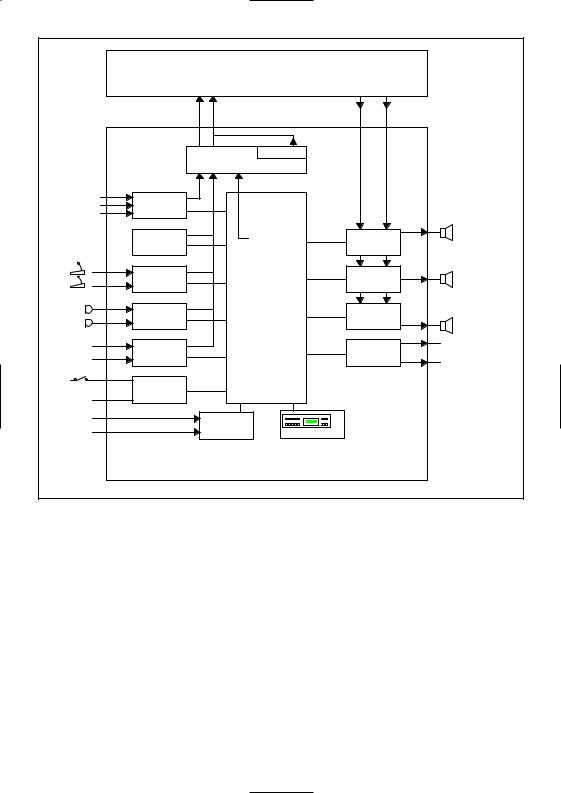
Block diagram
The block diagram of a SM30 system is shown in fig.1.
2
|
|
|
|
2-channel p.a. amplifier for |
|
|||||
|
|
|
SQ45 call and music applications |
|
||||||
|
|
|
music |
call |
|
|
|
|
|
|
|
|
|
input |
|
|
|
|
output |
|
|
|
|
|
1V |
|
|
|
|
100/70/50V |
|
|
|
|
|
|
|
Pilot tone |
|
|
|
|
|
|
|
|
|
Line output module |
|
|
|
|
|
|
Radio |
1 |
Music input |
|
|
|
|
|
|
|
|
Cassette |
2 |
|
|
|
|
|
|
|
||
C D |
3 |
module |
|
|
|
|
|
|
|
|
|
|
|
Recorded |
|
|
1Zone relay 1 |
Loudspeaker |
|||
|
|
|
|
Chime-, |
zones 1-6 |
|||||
|
message |
|
attention-, |
|
module |
|
|
|
||
|
|
|
module |
|
|
|
6 |
|
||
|
1 |
Call station 1 |
|
alarm-, |
2 |
Zone relay |
7 |
Loudspeaker |
||
|
|
signals |
||||||||
|
|
input |
|
|
|
|||||
|
2 |
|
|
|
module |
|
|
zones 7-12 |
||
|
|
module |
|
|
|
12 |
||||
|
|
|
|
|
|
|||||
|
3Microphone2 |
|
|
3 |
|
13 |
|
|||
|
|
|
input |
|
|
|
Zone relay |
|
Loudspeaker |
|
|
4 |
|
module |
|
|
|
module |
18 |
||
|
|
|
|
|
zones 13-18 |
|||||
|
|
|
|
|
|
|
|
|
|
|
|
5 |
Optional 3 |
Microprocessor |
|
|
|
1 |
|
||
|
Control relay |
Relay |
||||||||
|
|
|
input |
|
board |
|||||
|
6 |
|
|
|
module |
|
12 |
outputs 1-12 |
||
|
|
module |
|
|
|
|
||||
|
|
|
|
|
|
|
|
|||
|
1 |
|
|
|
|
|
|
|
|
|
|
Control input |
|
|
|
|
|
|
|
||
|
8 |
module |
|
|
|
|
|
|
|
|
AC |
|
|
|
Power |
|
|
|
|
|
|
DC |
|
|
|
supply |
Displ/keyboard |
|
|
|
|
|
|
|
|
|
|
|
|
|
|
||
|
|
|
|
|
Sound Management |
|
|
|
||
|
|
|
SM30 System |
|
4SM30011 |
|
||||
Fig. 1 - Block diagram
3

2 SYSTEM OPERATION
SM30 Sound Management System presents the operator with a logical, comprehensive, and easy to use method of routing and broadcasting calls, announcements, prerecorded messages, and music.
SM30 is easy to use and logical in its operation, but it is perhaps helpful to understand, in principle, how the system works.
A Typical Operation
Herewith a typical series of actions, initiated by the person (“the operator”) making an announcement, a paging call, etc., and carried out by the system.
1The operator selects in which loudspeaker zones the call must be broadcast. This is done by simply typing in the number of each desired zone using the Numeric Keypad of the Call Station. The Zone Routing Indicator LEDs for these zones will illuminate.
2The microprocessor, which is continuously monitoring the system, sees which key is pressed. First it looks to see whether another call is currently being broadcast. If so, the processor activates a flashing ‘BUSY’ LED on the call station.
3When the ‘PRESS TO TALK’ key is pressed, the processor checks which priority rating each Call Station, Function Key, microphone, etc., has been given, and if the original caller has a lower priority than the one being made, its call will be muted and overridden by the new caller. If the call being made has the same, or a lower priority than the original caller, the new call will be ignored, and the ‘BUSY’ led will be constantly illuminated to advise the operator that the call has been aborted.
Pressing the ‘REDIAL’ key will automatically reselect the zones which were last selected, eliminating the need to type them in again.
4If all is clear, the processor mutes any music signal which may be broadcast in the zone(s). Music routed to any other zones will not be affected.
5The processor checks which attention tone has been programmed to precede an announcement originating from the Call Station, then it switches on the built-in signal generator; selects a tone; and feeds it out to the amplifier input.
6If a message, recorded on the Recorded Message Module, has been programmed to precede a call, it will be broadcast after the attention signal, and before the call. Meanwhile the processor energises a flashing green ‘WAIT/TALK’ LED in order to tell the user that the call is going through, but that they will have to wait until the attention signal, or recorded message, has finished.
7The output signal of the amplifier is then input into the SM30 Control Centre, via its Zone Relay Module (a processor controlled routing/switching matrix), which routes it out again to the selected loudspeaker zones.
8When the announcement is completed and the ‘PRESS TO TALK’ key is released, the system returns to its idle mode, with the processor continually monitoring the system, until another call is made. If music was playing in the zone(s) it will return at its original volume level.
Activation of Control Relays
Generating a call could also activate a relay, or set of relays, which can be used to switch on (or off) external equipment.
4

Volume Control Override Relays
It is important that announcements and/or alarm signals come through at full volume, regardless of the volume settings of individual loudspeakers. The processor can be programmed to switch in a series of relays mounted on the Control Relay Card, which correspond to the loudspeaker zones selected. These in turn activate individual volume control override relays in the loudspeaker enclosures.
Using the Function Keys to Make a Call
Using the four Function Keys (mounted on the Call Station) to make a call is done in the same way as using the Keypad.
The main difference being that instead of the operator selecting the zones using the Numeric Keypad, the Function Keys route the call to a pre-programmed selection of zones.
This of course saves a great amount of time when an operator has to frequently call the same selection of zones, or when an “ALL CALL” must be made in emergencies.
The Function Keys can also be used to select and broadcast an alarm or attention tone, or activate a pre-recorded message, without any microphone generated call being made.
Whenever the function key is pressed its Function Key LED illuminates, along with any Zone Selection Indicators activated by the routing of the Function Key. When the call is completed the LEDs are extinguished.
Microphone and Control Input Calls
Calls, signals and/or pre-recorded messages, can also be activated by means of a microphone switch connected to the Microphone Input Module, and a remote switch wired to the Control Input Module (The last of course without a “live” call).
Power on delay
In order to conserve power for battery operated systems, the amplifier can be switched on only when a call is made.
It causes a time delay (programmable from 2-9 seconds) between pressing an activation key and the actual activation moment of the call. Relay 3 of the Control Relay Module is dedicated to switching the power to the amplifier(s).
Alarm interrupt
In order to conform with certain European military requirements an alarm call generated by a contact on a Control Input Module can be interrupted by a call with a higher priority. After releasing the relevant call key, the alarm signal will return for the programmed duration. Selection of the noninterrupted or interrupted mode is programmable in the “CTL ALARM MODE” program of the Installer Mode.
3ATTENTION AND ALARM SIGNALS
Built into the SM30 Control Centre is a signal generator, programmed with more than 40 attention tones and alarm signals. These can be programmed, via the User Menu, to proceed a call or pre-recorded message, or to be activated independently. As noted in the list below, some of these signals are terminated when the Call Station key, Control Input Relay, etc. is released. Other signals stop after about 1 minute, or when the Call Station activation key is pressed again. In order to confirm with STANAG (Standard Nato Agreement) requirements, an alarm signal can be interrupted by a call with higher priority. After releasing the call key, the alarm signal will return for the programmed duration. Along with the list below, chapter 6 (Call
5

Station) details the way in which each type |
11 |
Single tone, frequency 1000 Hz, 300 msec on, |
|
of call, when activated via the Call Station, |
|
200 msec off and repeating. Signal duration 5 |
|
can be terminated. |
|
sec. |
|
|
|
12 |
Slow whoop, sweeping from 500 up to |
Signal description |
|
1200 Hz in 3.5 seconds, followed by |
|
Signal numbers from 1 up to 12 are |
|
500 msec silence. This procedure will be |
|
attention or chime tones. The tone is quit as |
|
repeated twice. |
|
soon as the activating key is released. |
|
|
|
Signal numbers from 18 up to 50 are alarm |
Alarm Tones |
||
signals. |
18 |
Single tone, frequency 440 Hz. |
|
Alarm tones continue, even though the |
|
Signal duration 60 seconds. |
|
activating key is released. An alarm tone |
19 |
Single tone, frequency 440 Hz. Lasts until |
|
stops at the end of the signal duration or |
|
second activation. |
|
after activating the relevant key again. |
20 |
Sweeping signal, from 1200 Hz down to |
|
Signal numbers from 81 up to 87 are |
|
500 Hz and repeating. |
|
identical to 1 up to 7. |
|
Signal duration 60 seconds. |
|
These signals are meant for time signalling |
21 |
As signal number 20, lasts until second |
|
purposes. However, they will always finish |
|
activation. |
|
their cycle, even if the activating key is |
22 |
Alternating signal, frequencies 440 and |
|
released. |
|
554 Hz. |
|
|
|
|
Signal duration 60 seconds. |
Attention Chime Tones |
23 |
As signal 22, lasts until second activation. |
|
1 |
1-tone chime, frequency 554 Hz. |
24 |
Sweeping signal, from 100 up to 420 Hz in |
2 |
2-tone chime, frequencies 554 and 440 Hz. |
|
5 seconds, holding that frequency for |
3 |
3-tone chime, frequencies 392, 523 and |
|
60 seconds, sweeping down to 100 Hz in |
|
659 Hz. |
|
5 seconds and ending. |
4 |
3-tone chime, frequencies 659, 523 and |
25 |
Sweeping signal, from 100 up to 420 Hz in |
|
392 Hz. |
|
3 seconds, holding that frequency for |
5 |
4-tone chime, frequencies 554, 440, 493 and |
|
10 seconds, sweeping down to 300 Hz in |
|
330 Hz. |
|
3 seconds, holding that frequency for |
6 |
4-tone chime, frequencies 659, 523, 392 and |
|
10 seconds, repeating complete cycle until |
|
330 Hz. |
|
1 minute passed and ending. |
7 |
4-tone chime, frequencies 196, 262, 330 and |
26 |
STANAG all clear. |
|
392 Hz. |
|
Sweeping signal, from 1000 Hz down to |
8 |
Upsweeping signal, from 700 up to 880 Hz in |
|
650 Hz in 3 seconds, followed by 2 seconds |
|
400 msec, followed by 400 msec silence and |
|
silence and repeating. |
|
repeating. |
|
Signal duration 60 seconds. |
|
Signal duration 5 seconds. |
27 |
As signal 26, lasts until second activation. |
9 |
Alternating signal, frequencies 650 and |
28 |
Sweeping signal, from 700 up to 880 Hz in |
|
850 Hz. Signal duration 5 seconds. |
|
400 msec, followed by 400 msec silence and |
10 |
Up and down sweeping signal, frequencies |
|
repeating. Signal duration 60 seconds. |
|
500 and 600 Hz with sweeptime of 500 msec. |
29 |
As signal 28, lasts until second activation. |
|
|
|
|
Signal duration 5 seconds.
6

30 Alternating signal, frequencies of 650 and
850 Hz, every frequency lasts 500 msec. Signal duration 60 seconds.
31 As signal 30, lasts until second activation.
32 STANAG crash alarm.
Sweeping signal, from 500 up to 600 Hz in 500 msec, sweeping down to 500 Hz in 500 msec and repeating. Signal duration 60 seconds.
33 As signal 32, lasts until second activation.
34 STANAG fire alarm. Single tone, frequency 1000 Hz, 300 msec on and 200 msec off and repeating. Signal duration 60 seconds.
35 As signal 34, lasts until second activation.
36 STANAG air raid (red alert).Sweeping signal, from 900 up to 1000 Hz in 2.5 seconds, sweeping down to 900 Hz in 2.5 seconds and repeating. Signal duration 60 seconds.
37 As signal 36, lasts until second activation.
38 Single tone, frequency 1000 Hz. Signal duration 60 seconds.
39 As signal 38, lasts until second activation.
40 Character ‘F’ in morse, frequency 1000 Hz. Signal duration 60 seconds.
41 As signal 40, lasts until second activation.
42 Slow whoop, sweeping from 500 up to
1200 Hz in 3.5 seconds, followed by
500 msec silence and repeating. Signal duration 60 seconds or until second activation.
43 As signal 42, lasts until second activation.
44 STANAG NBC alarm (black alert). Sweeping signal, from 900 up to 1000 Hz in
2.5 seconds, sweeping down to 900 Hz in
2.5 seconds and repeating. Signal duration
60 seconds or until second activation.
45 As signal 44, lasts until second activation.
46 STANAG mortar attack alarm.
Sweeping signal, from 2000 down to 1700 Hz in 300 msec and repeating. Signal duration 60 seconds or until second activation.
47 As signal 46, lasts until second activation.
48 Muster alarm (ships).
Single signal, frequency 650 Hz, seven times 1 second on, 1 second off, followed by continuous signal. Signal duration 60 seconds or until second activation.
49 As signal 48, lasts until second activation.
50 Ship alarm.
Single tone, frequency 800 Hz, seven times 1 second on and 1 second off followed by 2 seconds on and 1 second off, and repeating until the next activation.
51 Catastrophe alarm.
Single tone, frequency 440Hz, 7 seconds on, followed by 19 times 3 seconds off and 4 seconds on. Signal duration 140 seconds.
52 General warning
Single tone, frequency 440 Hz, signal duration 140 seconds.
53 Fire Alarm
Frequency 440 Hz; 25 seconds on followed by 10 seconds off and repeating.
54 Important Message
(Swedish standard SS081711)
Single tone, frequency 600Hz, 6 times 6 seconds on, 12 seconds off. Signal duration 96 seconds.
55 All Clear (Swedish standard SS081711) Single tone, frequency 600 Hz, signal duration 30 seconds.
56 Immediate Danger (Swedish standard SS031711) Single tone of 600 Hz, 200 ms off. Signal duration 60 seconds.
99Dummy
Empty signal of 0.5 seconds, intended to precede a message from the recorded message module. This message should not be terminated if the activating key is released before the end of the message.
Time signals
81 1-tone chime, frequency 554 Hz.
82 2-tone chime, frequencies 554 and 440 Hz. 83 3-tone chime, frequencies 392, 523 and
659 Hz.
84 3-tone chime, frequencies 659, 523 and
392 Hz.
85 4-tone chime, frequencies 554, 440, 493 and 330 Hz.
86 4-tone chime, frequencies 659, 523, 392 and 330 Hz.
87 4-tone chime, frequencies 196, 262, 330 and 392 Hz.
7

4 CONTROL CENTRE LBB 1280
At the heart of each SM30 sound management system is the Control Centre. This is a self contained unit, housing the microprocessor which controls SM30, and 12 slots which hold the plug-in modules. On the front panel of the Control Centre are programming keys and associated LEDs, an alpha-numeric LCD display, and keys for controlling the functions of the music source inputs. The versatile construction allows the Control Centre to be mounted free-standing on a table top, or with other equipment, in a 19” rack. All of the interconnections between individual modules take place automatically when they are plugged into the interconnection board of the Control Centre, so that no complex inter wiring is required. Thanks to the unique construction of the housing, the modules slide in and out quickly and easily. These features make SM30 simple and inexpensive to install and maintain. All switching and routing of the system is carried out by software, so that hardwiring problems are kept to a minimum. This means that though SM30 comprises a great amount of features, making it a comprehensive Public Address Centre, the unit itself is uncluttered and simple to assemble and use.
4.1Front panel controls
ON/OFF Power Switch (fig.4.1A)
This rocker switch switches mains power to the SM30 Control Centre.
WARNING: When opening the SM30 housing or installing new modules, the mains lead and the 48 V DC battery plug must be removed. It is not sufficient to switch off the ON/OFF switch.
Programming Keys (fig.4.1C)
Ten programming keys are provided on the front panel. These keys, marked with logical symbols, enable the installer to program SM30 to suit the overall system configuration, and the user’s specific needs. For details, see chapter 14 (Programming).
and  (fig.4.1G)
The single arrow keys are used to scroll through the main menu, in order to move to a different program, and also to move the cursor during zone routing.
 and
and  (fig.4.1H)
The double up and down arrow keys are used to select ‘tens’ during selection of an attention or alarm signal number.
 and
and  (fig.4.1I)
The single up and down arrow keys are used to scroll through selections within an actual program, and to select digits 1 to 9 during selection of an attention or alarm signal number.
 (fig.4.1J)
Deselects (turns off) a zone during Function Key; Microphone; Control Input; and Music Source routing. (fig.4.1.N)
Selects (turns on) a zone during Function Key; Microphone; Control Input; and Music Source routing.
 (fig.4.1K)
BREAK will always return to the next higher programming level.
 (fig.4.1O)
ENTER will confirm your selection, storing the information in the memory of the system after the complete programming sequence of e.g keypad is completed.
LEDS (fig.4.1B)
Illuminated LEDs indicate which keys can be used at the current stage of programming.
8
Alpha-Numeric LCD Display (fig.4.1D)
In the normal ‘Run’ mode of the system, the back-lit LCD display indicates the name of the current music source (e.g. “TUNER”, or “MUSIC OFF”), plus the current music volume level.
LED (fig.4.1F)
A single LED is illuminated in ‘Run’ mode, indicating that the Music Function keys can be used.
Music Function Keys (fig.4.1E)
The current music source and the music volume level can be seen on the bottom line in the display.
Four keys are provided for use while the system is in its normal ‘Run’ mode. These allow the operator to select the music source; alter the volume level; and mute the music signal.
The keys are marked as follows:
+Music Volume up (fig.4.1L)
-Music Volume down (fig.4.1P) 0123 Music source Select (fig.4.1M)
Music Mute (fig.4.1Q)
When either ‘Music Volume up’ or ‘Music Volume down’ is pushed, the music volume changes in steps of ‘3’ over a range of ‘00’ to ‘99’ (Each step of 3 represents 2 dB, with ‘99’ equalling 0 dBV).
Any, or all of the four music control functions can also be activated via the:
■Function Keys on the Call Stations,
■Control inputs 1-4 on the Control Input Module.
|
|
A |
|
B |
C |
D |
E |
F |
|
S M30 |
|
|
|
|
|
|
|
PHILIPS |
PH ILIPS |
Power |
|
|
|
|
|
|
|
|
|
|
|
|
|
|
|
|
|
+ |
|
|
|
|
|
|
|
|
|
- |
|
G |
H |
I |
J |
K |
|
|
|
L |
M |
|
|
|
|
|
|
|
|
+ |
|
|
|
|
|
|
* SM 30 SYSTEM * |
|
|
|
|
|
|
|
|
|
TUNER 1 |
87 |
|
- |
|
|
|
|
|
|
|
|
|
|
|
|
|
|
N |
O |
|
|
|
P |
Q |
Fig. 4.1 - Front panel controls
9
4.2 SM30 basic modules
On delivery the rear panel of the SM30 Control Centre (fig.5.1) contains the Line Output Module and the Power Supply Module, as well as the removable blank module panels. (The last only in LBB 1280/30). Both modules are essential components, without which the SM30 system will not function.
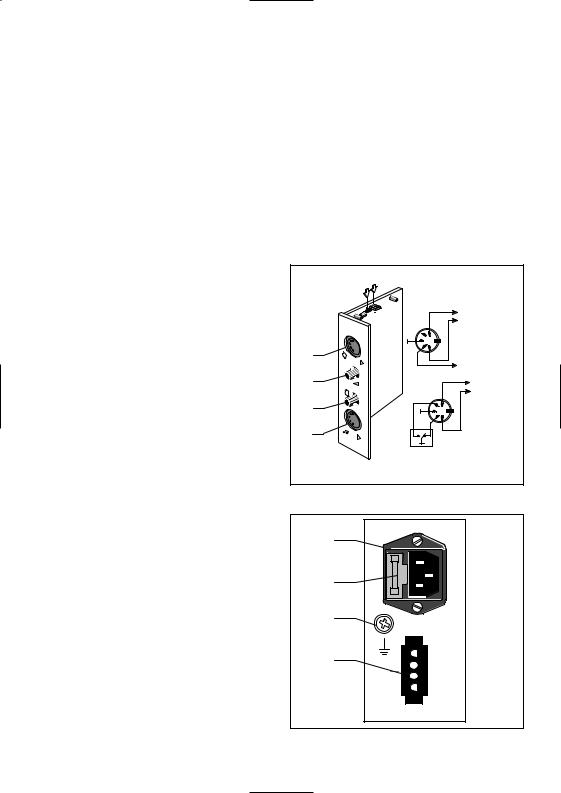
Line Output Module
As its name implies, the Line Output Module terminates line level audio signals for the ‘Call’ output (fig.4.2D) and ‘Music’ output (fig.4.2A).
These feed the inputs of their respective amplifiers. Both signals are terminated on 5- pole 180° DIN sockets, see fig.4.2 for wiring details. For amplifier surveillance purposes, it is possible to activate the built-in pilot tone generator by means of a switch (fig.4.2E) and to adjust the volume level (fig.4.2F).
The module is fitted on the frontpanel with two potentiometers; Alarm Volume Control (fig.4.2C) and Attention Tone Volume Control (fig.4.2B).
These allow the installer to set the output volume of the internal signal generator to the desired level for each of the two types of signal tone.
The output volume level of the Call signal has no preset (setting is done on both the Microphone Input Module and the Call Station Input Module).
Power Supply Module
This module contains the terminations for both the mains power and emergency +48 VDC supply. The mains power socket (fig.4.3A) is of the standard “Europlug” type, and has a mains fuse holder built in. To remove the mains fuse (fig.4.3B), first
remove the mains power cable (cord) from the socket, and carefully insert a medium sized screwdriver under the small lip of the fuse cover (nearest the socket pins), and gently twist the screwdriver to lever the fuse holder out. A ‘Mate-N-Lok’ emergency supply socket (fig.4.3D) is provided to allow a +48 VDC supply to be connected.
An Earth terminal (fig.4.3C) is mounted on the Power Supply Module to allow an extra earth (ground) wire to be connected for use with the Emergency Power Supply, or when the mains power earth is inadequate.
E F
|
|
symmetric |
|
|
Call Out |
4 |
1 |
|
2 |
3 |
|
5 |
|
|
D |
|
Test signal |
|
|
20 kHz |
C |
|
symmetric |
|
|
Music out |
B |
4 |
1 |
|
2 |
3 |
|
5 |
|
A |
SM30 relay not active |
|
|
||
|
during Call. |
|
Fig. 4.2
A
B
C
D
+48
Fig. 4.3
10
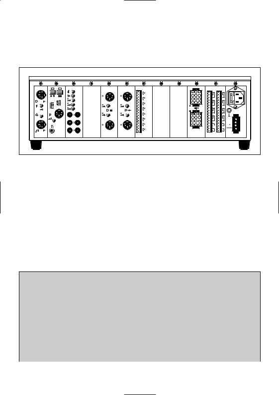
5.SETTING UP THE HARDWARE the Power Supply Module (PSM) mounted
5.1General
The SM30 Control Centre is delivered with only the Line Output Module (LOM) and
in their slots. All other modules must be fitted into their respective slots as indicated in fig.5.1. A survey of configurations with the maximal number of input modules is given in the table.
LOM R M M |
M U M |
|
C S M |
M I M |
CIM |
|
|
ZR M |
C R M |
P S M |
|
|
|
|
|
|
|
|
|
2 |
1 |
|
|
|
|
|
|
|
|
|
|
|
|
|
|
|
|
|
|
|
|
4 |
3 |
|
|
|
|
|
|
|
|
|
6 |
5 |
|
|
|
|
|
|
|
|
|
8 |
7 |
|
|
|
|
|
|
|
|
|
10 |
9 |
|
|
|
|
|
|
|
|
|
|
|
|
|
|
|
|
|
|
|
|
12 |
11 |
L BB 1 2 8 5 |
L B B 1 28 6 |
|
L B B 1283 |
LBB 1282 |
L B B 1 28 4 |
|
|
LB B 1287 |
LB B 1288 |
|
|
|
|
|
|
|
|
|
|
||
A |
B |
C |
D |
E |
F |
G |
H |
I |
J |
|
Line Output Module |
|
X |
|
|
|
|
|
|||
Music and call output signal to amplifier |
|
|
|
LBB 1285/00 Recorded Message Module |
A |
|
|
4 messages = 29,5 sec |
|
|
|
LBB 1286/10 Music Input Module |
B |
|
|
3 music sources |
|
|
|
LBB 1282/00 Microphone Input Module |
C |
D |
E |
2 microphones max. 3 modules = 6 microphones |
|
|
|
LBB 1283/00 Call Station Input Module |
C |
D |
E |
2 Call Stations max. 3 modules = 6 Call Stations |
|
|
|
LBB 1284/00 Contact Input Module |
|
D |
E F |
8 contacts max. 3 modules = 24 contacts |
|
|
|
LBB 1287/00 Zone Relay Module |
|
|
G H I |
6 loudspeaker zones max. 3 modules = 18 zones |
|
|
|
LBB 1288/00 Control Relay Module |
|
|
J |
12 relays, only 9 or 10 relays free to programme |
|
|
|
Power Supply Module |
|
|
X |
220 V mains supply +48 V battery supply |
|
|
|
Maximal configuration of input modules
CSM pos |
Call Station numb. |
MIM pos |
Microphone numb. |
CIM pos |
Contact numb. |
|
|
|
|
|
|
- |
- |
- |
- |
F,E,D, |
1/8, 9/16, 17/24 |
- |
- |
C |
5/6 |
F,E,D, |
1/8, 9/16, 17/24 |
- |
- |
D,C |
3/4, 5/6 |
F,E |
1/8, 9/16 |
- |
- |
E,D,C |
1/2, 3/4, 5/6 |
F |
1/8 |
C |
5/6 |
- |
- |
F,E,D |
1/8, 9/16, 17/24 |
C |
5/6 |
D |
3/4 |
F,E |
1/8, 9/16 |
C |
5/6 |
E,D |
1/2, 3/4 |
F |
1/8 |
D,C |
3/4, 5/6 |
- |
- |
F,E |
1/8, 9/16 |
D,C |
3/4, 5/6 |
E |
1/2 |
F |
1/8 |
E,D,C, |
1/2, 3/4, 5/6 |
- |
- |
F |
1/8 |
|
|
|
|
|
|
Fig. 5.1
11
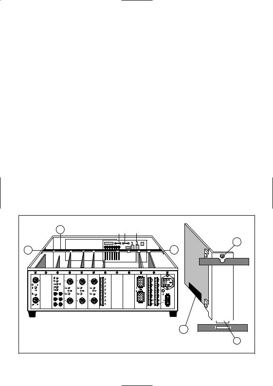
5.2Opening the housing
WARNING: Before attempting to open the housing, the mains lead and the 48 V DC battery plug should be disconnected. It is not sufficient to merely switch off the ON/OFF switch on the front panel.
Access to the inside of the Control Centre is gained by removing the cover. This is done by removing the four ‘cross-head’ screws located in the sides of the unit. The cover is then simply lifted off the housing. When the cover is removed, a ‘retaining bar’ (fig.5.2A) will be seen spanning the top of the housing. This should now be removed by loosening (not removing) the screws located in its ends.
To access the screw heads, the screwdriver must be inserted through the holes in the sides of the housing (fig.5.2B). With the screws loosened a little, the bar can be slid vertically out of the screw slots.
Removing Module Blank Panels
The module blank panels are removed in a similar way, by loosening the cross-head screws a little and sliding the panels vertically out of their keyhole slots.
Mounting the Modules
Before inserting the modules, read their respective chapters to make sure that there are no jumpers that need to be set in order to carry out the desired function(s). The modules are located, as illustrated in fig.5.1, by aligning the front plate screw with the keyhole slot (fig.5.2C); the key at the bottom of the front plate (fig.5.2D) with the slot in the bottom of the housing; and the multi connector (fig.5.2E) with the socket mounted on the mother board. The module is then gently pushed into place by putting pressure on the top of the circuit board. If it does not slot easily into place do not attempt to force it. Check that it is properly aligned and try again. When the modules are inserted, and properly seated in their connectors, tighten their front plate screws.
A |
|
|
FUSE 1- 2 |
X3 |
|
|
|
|
|
|
|
|
|
|
|
|
C |
B |
|
|
|
|
B |
LBB 1286 LB B 1283 |
LB B 1282 |
LB B 1282 |
LBB 1 284 |
LBB 1287 |
LBB 1288 |
|
|
|
|
|
E |
|
|
|
|
|
D |
Fig. 5.2 - Top view
12
The retaining bar (fig.5.2A) can now be replaced by sliding it down in its slots as far as possible, and tightening the screws in its ends (fig.5.2B).
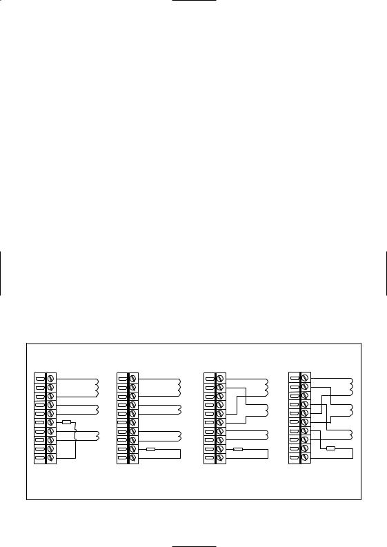
5.3Voltage Setting
The system is delivered with the mains transformer wired for 220 Volts AC.
Before attempting to switch on the unit ensure that the voltage is set correctly for your mains supply.
To change the voltage, unplug the long (grey coloured) screw connector block (fig. 5.2X3), and rewire it for the appropriate voltage, shown in the circuit diagram (fig.5.3). Push the connector block firmly back into place. The cover of the Control Centre can now be replaced, and the screws reinserted in the side panels.
48 Volt Emergency Power Supply
In situations where the mains power supply is unreliable, and SM30 is used for security/evacuation purposes, an emergency power supply may be used. This can be switched in automatically whenever the mains power fails.
A 4-pole ‘Mate-N-Lok’ socket (fig.4.3D) is provided on the Power Supply Module on the back panel, to allow a +48 VDC supply to be connected. The terminations for the supply are clearly marked alongside the Mate-N-Lok socket. The emergency supply plug should be wired accordingly.
Earth Terminal (ground)
An Earth Terminal (fig.4.3C) is mounted on the Power Supply Module to allow an extra earth (ground) wire to be connected.
This should be used when the Emergency Power Supply is used alone, or when the mains power earth is inadequate.
If audible interference is present in the system, caused by an inadequate, or contaminated earth (e.g. due to heavy equipment using the same common earth), a separate “clean” earth may be connected to the Earth Terminal.
X3 |
X3 |
|
X3 |
|
X3 |
|
R E D |
|
R ED |
R ED |
R ED |
|
GR N |
|
G R N |
GR N |
G R N |
|
B L K |
|
B L K |
B L K |
B L K |
|
YE L |
|
YE L |
YE L |
YE L |
|
BL UE |
|
BLU E |
BL UE |
BLU E |
|
BR N |
|
B R N |
BR N |
B R N |
220V230V |
|
240V |
127V |
|
110V |
Fig. 5.2 - Top view
13

5.4Mounting in a 19” rack
The SM30 Control Centre is available in two versions:
LBB 1280/30 for table top use including the cover.
LBB 1280/40 for 19” rack mounting, without cover but including the mounting brackets.
Removing Feet
WARNING: Before attempting to open the housing, the mains lead and the 48 V DC battery plug should be disconnected. It is not sufficient to merely switch off the ON/OFF switch on the front panel.
The feet of the Control Centre may be removed for rack mounting if space is limited. To remove the feet simply unscrew the cross-headed screw which is recessed in the centre of each foot.
If rack space is not limited however, it is preferable to leave the feet in position and to mount a narrow blank rack panel beneath the unit. If the Control Centre then has to be removed for servicing, the feet will protect the surface of furniture from being
scratched by metal components of SM30.
Calculating Required Rack Space
To simplify ordering of modular units and panels to fit into standard 19” rack units, Philips have chosen a standard height ‘HE’ equal to 44.55 mm (1.75 inches). Each SM30 Control Centre, for instance, is 3 HE high, requiring 133.65 mm of rack space. The use of the HE unit eases the problem of calculating the number of equipment housings, blank panels, etc. that will fit into a rack.
General Rules
Certain rules should be observed when planning the equipment layout in a rack:
1To ensure that the SM30 display is clearly visible, and the controls are easy to operate, the Control Centre should be mounted at a height which makes it easily accessible (head, or shoulder height if possible).
2Cassette front loaders, tuner scales, and other frequently used equipment, should be mounted at a height which makes their front panels clearly visible to the operator.
SM3 0 |
PHILIPS |
|
|
Powe r |
|
|
+ |
3H E |
|
|
- |
Fig. 5.4 - Rack mounting
14

3It is always preferable to mount power amplifiers, which generate a certain amount of heat, above heat sensitive equipment, like SM30.If however, power amplifiers must be mounted beneath the Control Centre, a heat shield should be installed above them. This is necessary to deflect the hot air currents, which could otherwise cause instability in the SM30 microprocessor controlled units.
5.5Connecting amplifiers
The SM30 system is intended for use with 2 separate amplifiers, or two separate channels of a multi channel amplifier. One channel will handle the ‘call’ signal, and the other channel will amplify the ‘music’ signal. This allows the music signal to continue, uninterrupted, when a call is made to other loudspeaker zones. It is possible to use only 1 amplifier channel for both the ‘calls’ and ‘music’ signal. This has the disadvantage however, that any music playing will be interrupted whenever a call is made, regardless of the zone(s) to which the call is routed. Though the SM30 system will work with any line level input amplifier, the amplifiers from the Philips SQ45 range have been specifically designed to take the greatest advantage of the functions of SM30.
Two Channel System (fig.5.5.1) Connections of SM30 to two amplifiers, or two channels of a Philips SQ45 amplifier:
1Connect both the ‘Call’ and ‘Music’ outputs of the Line Output Module, to the separate ‘Call’ inputs of the SQ45 amplifier(s).
2Connect the outputs of the amplifiers (with two core loudspeaker cable) to their respective ‘Call’ and ‘Music’ inputs on the ‘Mate-N-Lok’ connector on the Zone Relay Module of the SM30.
One Channel System (fig.5.5.2)
When using a single amplifier system, the following steps must be taken:
1The ‘Call’ and ‘Music’ outputs of the Line Output Module should be connected to their respective ‘Call’ and ‘Music’ inputs on the SQ45 amplifier. The relay on the Line Output Module will switch the active input of the SQ45 amplifier from music to call.
See the relevant SQ45 amplifier Instructions For Use for details of this function.
2The output of the amplifier has to be connected to the ‘Call’ input on the ‘Mate-N-Lok’ on the SM30 Zone Relay Module.
3Refer to Installer Program step 9 to program this function.
As previously stated, zones with music will be interrupted for as long as a call to any other zone(s) lasts.
Rack Mounting
If the amplifier(s) and SM30 are mounted in a rack unit, and an ‘earth loop’ occurs (evident by a 50 or 60 Hz hum through the loudspeakers) follow the Instructions For Use given with the SQ45 amplifier for details of earthing the units.
15

C
3
3 |
1 |
1 |
C |
4X
SQ45 |
SM30 |
Fig. 5.5.1 - Two channel system
16

C |
3 |
1 |
1 |
SQ45 |
SM30 |
Fig. 5.5.2 - One channel system
17

6 |
CALL STATION |
|
|
(CST) |
LBB 9568 |
The SM30 Call Station presents the operator with a logical, comprehensive, and easy to use method of routing and broadcasting calls, announcements, and music. Since each Call Station Input Module will accept two Call Stations, SM30 will accept up to 6 Call Stations in total.
Electret condenser microphone
The high quality phantom powered microphone with built-in bass rolloff filter (fig.6.1L) gives clear voice reproduction, even in difficult acoustic environments.
Built-in Compressor
Helps to keep the audio output level of the Call Station constant, even in situations where the operator’s speech volume level changes radically. The amount of compression is dependent on the Microphone preamplifier gain setting: the higher the gain setting, the greater the amount of compression, and therefore the greater the effect on the microphone signal (see paragraph 6.3).
Balanced Line Level output
Allows Call Stations to be located up to 1000 metres from the Control Centre.
6.1Operating controls
Numeric Keypad (fig.6.1J)
Allowing individual selection of up to 18 loudspeaker zones by typing in the zone number. Each Call Station can be programmed with a priority status, attention tone and pre-recorded message. These become operational whenever the keypad is used to route a call. (See chapter 14 for programming details).
Redial function (fig.6.1I)
Repeats the last zone selection.
Zone Selection Indicator (fig.6.1B) Each zone has its own LED which is
illuminated when the zone is selected. When the call is completed the LEDs will be extinguished.
Function Keys (fig.6.1K)
The 4 function keys are to be programmed with priority; alarm and attention tones; pre-recorded messages; routing to loudspeaker zones; and Control Relay activation. The alternative functions of these keys include: music volume up/down; music source selection; music mute; and independent Control Relay switching or toggling (see chapter 14 for programming details). Using the Function Keys to make a call is done in the same way as using the Keypad. The main difference being that instead of the operator selecting the zones using the Numeric Keypad, the Function Keys route the call to a pre-programmed selection of zones. This of course saves a great amount of time when an operator has to frequently call the same selection of zones, or when an “ALL CALL” must be made in emergencies. Each Function Key may be programmed to carry out a totally different task.
Key F1 can be programmed to route a low priority call, preceded by an attention tone, to several, frequently used, loudspeaker zones.
Key F2 could be programmed to route an alarm tone, followed by a pre-recorded evacuation message, to all loudspeaker zones (an “ALL CALL”).
Key F3 could be used to mute the music signal.
Key F4 could be used to toggle a Control Relay on and off, switching a warning lamp, illuminated notice, etc..
18
NOTE: If a Function Key and the Keypad are both selected to activate a call, the last selection will always have precedence, cancelling any other selection.
During Installer programming a program is available to prevent the user of the Call Station from addressing specific zones selected via the keypad (see program 14.3.12).
Function Key LED (fig.6.1A) Whenever a Function Key is pressed the
LED illuminates, together with any Zone Selection Indicators activated by the routing of the Function Key. When the call is completed the LEDs will be extinguished.
‘Press-To-Talk’ Key (fig.6.1H)
Activates a call after the zones have been preselected using the Key Pad or Function Key. The way in which a call is executed, and how the ‘Press-To-Talk Key’ is used, depends on the type of signal and/or message with which the Key Pad, Function Key, or Microphone is programmed.
■Call without signal or message:
Will stop when the ‘Press-To-Talk’ Key is released.
■Call with attention signal and/or nonrepeating message:
Will stop when the ‘Press-To-Talk’ Key is released.
■Call with attention signal and repeating pre-recorded message:
The message and/or signal cycle will continue after the ‘Press-To-Talk’ Key is released. The cycle can be stopped by pressing the ‘Press-To-Talk’ Key a second time.
If this is done during the attention signal, the call stops immediately.
If the message is playing, the call will stop at the end of the message.
■Call with alarm signal:
The alarm signal will continue after release of the ‘Press-To-Talk’ Key.
It can be stopped by pressing the ‘Press- To-Talk’ Key a second time.
Busy and wait/talk LEDs
(fig.6.1F and 6.1G)
Advise the operator whether a call may be activated, the status of the call, and whether any other calls are active.
The red ‘BUSY’ LED flashing means that another call is in progress.
The red ‘BUSY’ LED illuminated constantly indicates that the call has been blocked by another call with a higher priority.
In its ‘WAIT’ state, the green LED flashes, indicating that the call is accepted, and the attention tone or pre-recorded message is being broadcast.
The green LED illuminates constantly (‘TALK’) when the tone or message finishes and the processor switches on the microphone for the call to proceed.
|
A |
|
|
B |
|
C |
|
|
|
|
|
|
D |
|
|
|
|
|
|
E |
|
|
|
|
|
|
F |
|
F1 |
1 |
2 |
3 |
|
|
|
F 2 |
4 |
5 |
6 |
|
G |
|
|
|
|
|
|
|
|
F 3 |
7 |
8 |
9 |
|
|
|
F 4 |
1 - |
0 |
# |
|
H |
|
|
|
|
|
|
|
|
|
|
|
|
PHILIPS |
PHIL IPS |
|
|
|
|
|
|
|
L |
K |
|
J |
I |
|
|
Fig. 6.1 - Call Station
19
6.2Installation
Loudspeaker Zone Template
A paper template is provided, on which the names of the loudspeaker zones can be written. The template has a detachable blank section at the bottom, allowing it to be used in a typewriter.
To mount the template in the Call Station, first remove the right hand side cheek (fig.6.1D), by unscrewing the two screws in its side (fig.6.1E), and the one screw located in the bottom. The plastic template cover (fig.6.1C) can now be slid out. Place the (type) written template in position over the zone LEDs (having first torn off its blank perforated panel), and carefully slide the plastic template cover back in place.
Connection to Control Centre
Between the Call Station and the Call Station Input Module (see chapter 7.1) the following cabling is needed::
■a shielded twisted pair for audio and power transport;
■a twisted pair for data transport. When the copper diameter of each wire is not less than 0.75 mm2 the length of the cable can be up to 1000 meters for proper functioning.
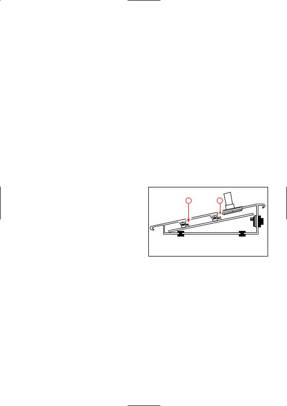
6.3Adjustments
Microphone Pre-amplifier Gain Preset
With the right hand side cheek of the Call Station removed, the microphone preamplifier’s gain can be preset. Turning the potentiometer (fig.6.2B) to the right increases the amount of gain. To obtain nominal 1 Volt output level, the gain can be preset from 84 to 114 dB SPL.
NOTE: The Call Station Input Modules also have input gain presets. The
Microphone Preamplifier Gain Preset should only be used for setting the amount of compression, not for lining up the Call Station output with the rest of the SM30 System. See ‘Built-in Compressor’ earlier in this chapter.
LED Intensity Preset
With the right hand side cheek removed, it is possible to gain access to the LED intensity preset.
To compensate for various local lighting conditions, the illumination intensity of the LEDs can be adjusted. Turning the potentiometer (fig.6.2A) to the right increases the intensity.
With the template and its cover in position, and the microphone volume and LED intensity adjusted, replace the right hand side cheek.
A |
B |
Fig. 6.2 - CST adjustments
6.4Using the Call Station
Using the Keypad to make a Call
1To route a call to one or more loudspeaker zones, simply type in the number of each desired zone using the numeric keypad. Numbers ‘1’ to ‘9’ allow single digit numbers to be entered, number ‘1-’ is for tens, and ‘0’ is the second digit in the number 10. For instance, to route a call to zones 7, 10, and 15, type in: 7, then 1-, then 0; then
20
 Loading...