


MZ-9

Service
Service
Service
Service
MZ-9/22
A02 - 174
Service
Product Service Group CE Audio
Service Information
Already published Service Informations :
CHANGES DURING PRODUCTION
FRONT BOARD
*From production week 0217 onwards the following has been changed
to solve Thin/Thick Disc readability problem and to improve on the
Tape transition timings.
Change 7400 3139 110 53251 TMP87CS71F - 'MZ9S53251'
*From production week 0225 onwards the following has been changed
due to material end of life.
Change 7402 9322 140 83682 IC M24C01-BN6
ETF7 ND/DD/FR TAPE MODULE
*From production week 0218 onwards the ETF7 ND/DD/FR Tape
Module is introduced to replace the ETF5-FE ND/DD/FR Tape
Module for cost savings. For this reason new layout and circuit
drawing are enclosed (Page 9-1 to 9-14).
10 - 09 - 2002
3139 785 30089
9-1
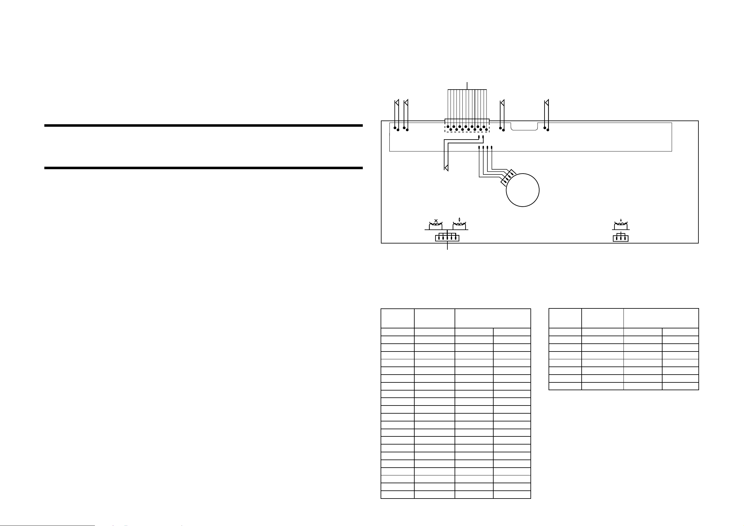
ETF7 TAPE MODULE
Tapedeck wiring (Double deck)
TO ETF BOARD
CONNECTOR 1770 (ND) 14P
CONNECTOR 1740 (DB) 14P
REC
REV
CRO2*
REC
FWD
9-1
CRO2*
* Not for Ferro version
(Non-Dolby Version)
TABLE OF CONTENTS
Tape Module Wiring & variation table ....................... 9-1
Block diagram ............................................................ 9-2
Brief Introduction ....................................................... 9-3
Connector assignment............................................... 9-4
Tape deck electronics & Tape adjustments ............... 9-5
ETF7 Non-Dolby board layouts ................................. 9-6
Analog Circuit diagram .............................................. 9-7
Servo Circuit diagram ................................................ 9-8
Exploded views & parts list........................................ 9-9
Electrical parts list.................................................... 9-13
MODE
SW
Mechanism B Mechanism A
TO ETF BOARD
CONNECTOR 1710 (ND) 5P
CONNECTOR 1720 (DB) 6P
–
+
H
L
TAPE DECK
MOTOR
TO ETF BOARD
CONNECTOR 1730 (3P)
Variations table for Analog Circuit
Autoreverse Non-autoreverse
ND/DD/FR ND/DD/FF
Chrome/Ferro Chrome/Ferro Ferro
2624 - - 100nF
2701 , 2702 150pF 270pF 270pF
2703 , 2704 100pF 220pF 220pF
2717 , 2718 10nF 15nF 15nF
2721 , 2722 6,8nF 6,8nF 2727 , 2728 470pF 1nF 1nF
3616 10k 1k 1k
3618 6k8 - 3620 10k trimmer - 3622 - 10k trimmer 10k trimmer
3672 4k7 - 3676 47k - 3687 220R 220R 3688 680R - 3723 , 3724 15k 18k 18k
3725 , 3726 10R 10R 3727 , 3728 5k6 6k8 6k8
3729 , 3730 3k3 4k7 4k7
3743 , 3744 1k5 2k2 2k2
3745 , 3746 3k3 5k6 5k6
3754 , 3755 1M 47R 47R
3769 12k 8k2 8k2
3772 6k8 5k6 5k6
4785 - - 0R jumper
3774 15k 8k2 8k2
6614 1N4148 - 7616 BC857B - 7622 BC847B - -
Autoreverse Non-autoreverse
ND/DD/FR ND/DD/FF
Chrome/Ferro Chrome/Ferro Ferro
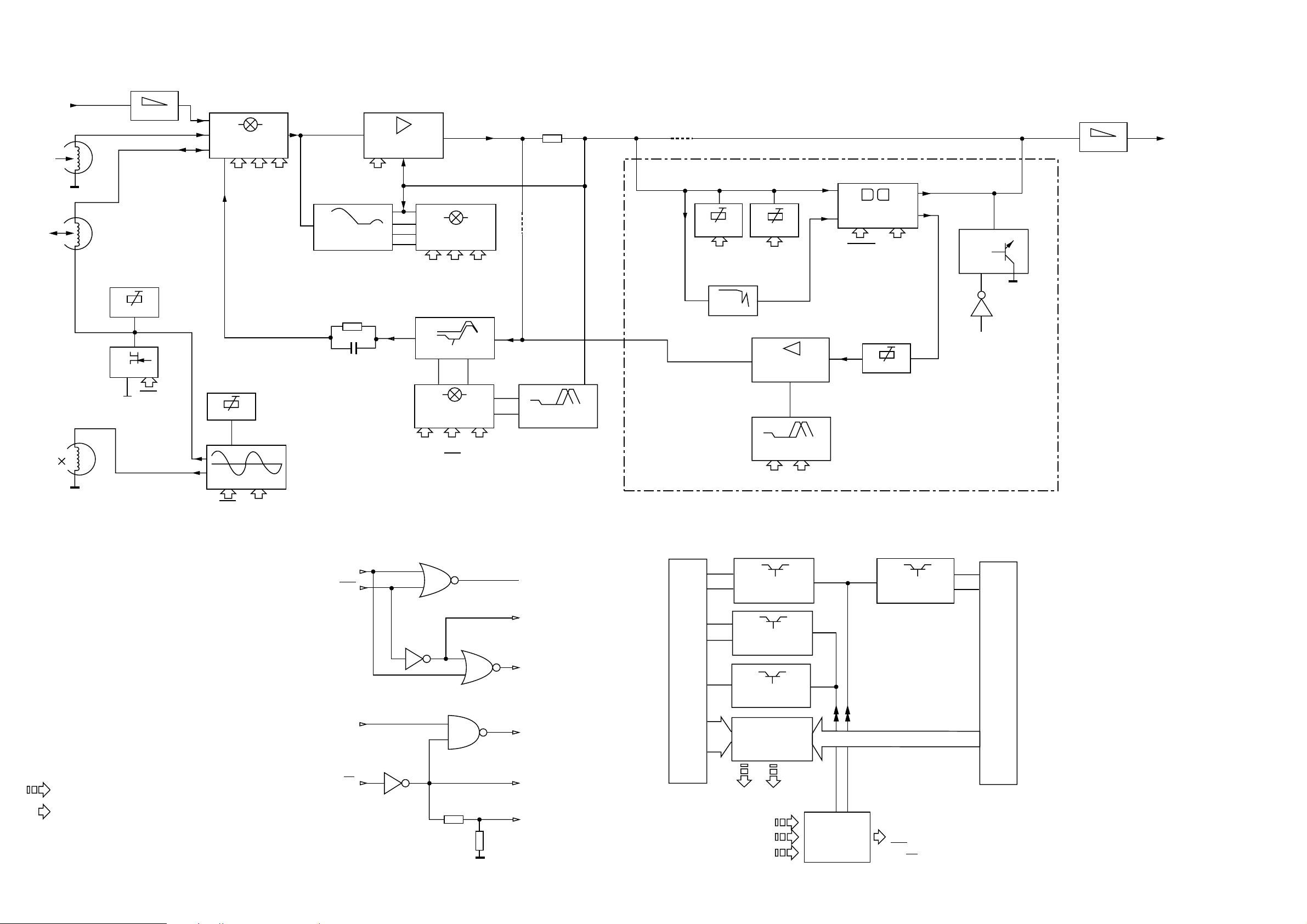
BLOCK DIAGRAM
9-2
9-2
Line-In
Playback
Head
Rec/Pb
Head
Erase
Head
ATTEN
BIAS SYM
HD SW.
REC
Rec current
BIAS ADJ
Bias
7710
SOURCE SEL
HEF4952BT
1A0 1A1 1A2
7720
PRE-AMPLIFIER
AN7318S
ALCEN
PLAYBACK
EQUALISATION
ALC
7740
PB EON. SW.
HEF4952BT
2A0 2A1 2A2
IEC I IEC II
REC EON.
7730
REC EON. SW.
HEF4952BT
3A0 3A1 3A2
(HS) (REC) (CRB)
4794 #
#
NOM/HI SPEED
REC EON.
9792 #
For Dolby version only
PB A ADJ
1A0
MPX
Rec In
PB B ADJ
1A1
7640
RECORD AMP
NJM4560D
NOM/HI SPEED
REC EON.
PB In
7630
DOLBY B NR
CXA1101M
DOLBY
REC ADJ
2A2
PB Out
ATTEN
PB Out
REC Out
MUTE
7788
2A2
NOTE:
Erase
# For Non-dolby version only
Only 1 channel is presented.
MicroProcessor Control / Communication lines
Direct / Indirect Control lines from Shift Registers
OSCILLATOR
REC
CRB
1A0
REC
CRA
NS/HS
(NS)
7622
7780
7787
7792
7791
ALCEN
1A2
1A1
2A0
HS
3A0
3A0 NS
4x
SOLENOID
SUPPLY CTRL
MOTOR VCC
SUPPLY CTRL
NS/HS CTRL
DECK(S) SW.
STATUS TO
VOLTS CONV.
2x
SOLENOID
SUPPLY CTRL
Deck B (Rec/Pb) switches, sensors & motor
AD1 AD2
CLK
DATA
STROBE
7610
SHIFT
REGISTER
HEF4094BT
1A0
2A1
2A2
REC
NS/HS (NS)
Deck A (Pb) switches, sensors & motor

9-3 9-3
Brief introduction
General
1.
Playback Mode
Signal from the playback head Deck A or Deck B is selected and fed through by the Mode Selector IC7710 (HEF4952BT).
The signal is amplified by amplifier IC7720 (AN7323S) before feeding to the IC7740 (HEF4952BT) and out to the AF Board
via connector 1701.
Recording Mode
2.
Recording Signal is selected and fed through by the Mode Selector IC7710 (HEF4952BT) which is then amplified by the
amplifier IC7720 (AN7323S). The amplified output signal will pass through IC7730 (HEF4952BT) for record equalization and
back to IC7710 (HEF4952BT) before registered into the Rec/PB Head of Deck B.
3.
Dubbing Mode
In Dubbing mode, signal from the playback head Deck A is selected and fed through by the Mode Selector IC7710
(HEF4952BT) which is then equalised for playback mode by the amplifier IC7720 (AN7323S) so that a flat response is
obtained after the pre-amp. The equalised signal will then follow the same path as in the Recording mode.
Mode Selector
4.
The Mode Selector IC7710 (HEF4952BT) caters for 4 inputs signal, namely Playback Signal from Deck A, Playback Signal
from Deck B, Recording Signal and Dubbing Signal.
5. Amplifier PB/REC
Amplifier IC7720 (AN7323S) is for the purpose of amplifying the Playback and Recording signal from the Mode Selector.
6.
Automatic Level Control (ALC)
ALC circuit consists of resistors (3760, 3765, 3766, 3767), capacitors (2762 , 2763) and control by transistor 7787 (BC847B).
ALC limits the amplifier output to a constant value when input signal becomes too large, thus limiting recording current to
below saturation level, to prevent recording distortion.
Muting Circuit (For Non-Dolby version only)
7.
Switch S4 of the IC7740 (HEF4952BT) is for the purpose of muting the output during Recording mode. During Recording
mode, S4 is closed and shorted to the ground.
8. IC7740 (HEF4952BT)
The function of the IC7740 (HEF4952BT) is to change time constant between 120us Ferro (IEC I) and 70us Chrome (IEC
II) during playback mode. It will automatically determined whether the tape type is 120us Ferro (IEC I) or 70us Chrome (IEC
II). This IC will switch to Flat Gain during the Recording mode.
9.
IC7730 (HEF4952BT)
The function of the IC7730 (HEF4952BT) is to change gain and time constant according to tape type and recording speed
to boost recording current at higher frequency during recording to compensate for head loss. It will automatically determined
whether the tape type is 120us Ferro (IEC I ) or 70us Chrome (IEC II).
Bias Level
10.
Bias Level making use of the Variable resistor (3773) for adjusting the optimal level of the bias current for Ferro or Chrome.
11.
Bias Symm (For Dolby B NR version only)
Bias Symm making use of the Variable resistor (3785) to adjust the bias current for the left and the right channel to be equal.
PB Switch
12.
Playback Switch which consists of the FETs 7785 (For Dolby B NR version only) & 7786 (J111) is for the purpose of providing
a virtual ground for the Rec/PB Head (Deck B) during Playback mode. During the Playback mode, the FETs are turn on and
shorted pin 2 and 4 of connector 1720 to the ground. During Recording mode, the FETs are turn off to allow the oscillator
signal to be superposition onto the Recording signal for recording.
13.
Motor Speed (For FR versions only)
During High speed dubbing, a feedback signal from the uP through pin 03 of the IC7610 (HEF4094BT) will trigger the
transistors 7622 (BC847B) and 7616 (BC857B) to cause a change in the voltage level between High and Low, thus changing
the speed of the motor.
IC7610 (HEF4094BT)
14.
IC7610 (HEF4094BT) is a Shift Register use for issues the logic for cmos switch ICs (HEF4952BT) via 1A0, 2A1 and 2A2.
It also issues logic to On/Off SOL_A, SOL_B and MOT. Recording speed is controlled via NS/HS.
Dolby Circuit (For sets with Dolby B NR version only)
15.
IC7630 (CXA1551M)
IC7630 (CXA1551M) in the Dolby circuit is a Dolby Noise Reduction Type B IC for the Playback and Recording signal. Noise
Reduction ON/OFF are controlled by DOLBY, which is from CLK, direct from uP. After clocking in DATA, CLK is set to HIGH/
LOW for NR OFF/ON.
19kHz Filter
16.
The 19kHz filters 5631 & 5632 (LXD-210) in the Dolby circuit is for the purpose of filtering the 19kHz Pilot Tone (for Tuner
signal only) of the Recording signal.
17. Level Adjust
The Variable resistor 3635, 3636,3641 and 3642 in the Dolby circuit is for adjusting the playback level of the Dolby reference
(400Hz , 200nWb/m). Transistor 7631, 7632 are ON to enable adjustment of 3641, 3642 during Playback Deck A. Transistor
7633, 7634 and 3635, 3636 are active for Playback Deck B.
18.
Amplifier IC7640 (NJM4560M)
The Amplifiers 7640A & 7640B (NJM4560M) in the Dolby circuit is for the purpose of amplified the Recording signal.
Muting Circuit
19.
The muting circuit which consists of transistors 7788, 7789 and 7790 (BC847B) is for the purpose of muting the output during
Recording mode.
NOTATIONS & ABBREVIATIONS USED IN THIS
DOCUMENT
CR Chrome (IEC type II)
DB Dolby NR type B
DD Double Deck
DM Double Motor
FE Ferro (IEC type I)
FF Non-Autoreverse
FR Autoreverse Deck B
Gnd x Ground x
HSD High speed dubbing
ND Non Dolby
NR Noise Reduction
NSD Normal speed dubbing
PB Playback
REC Record
S/A Sub-assy
SD Single Deck
SM Single Motor
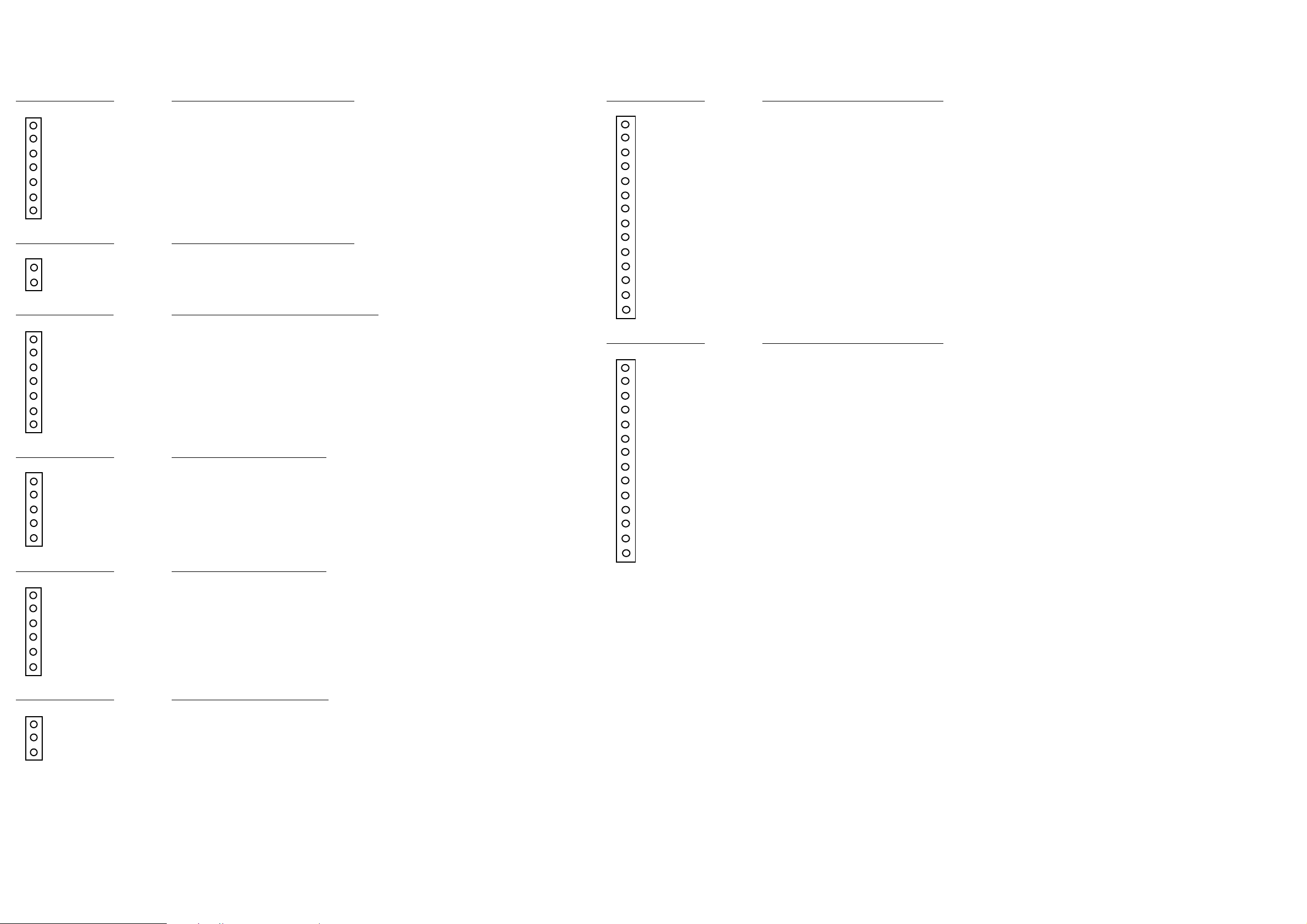
CONNECTORS ASSIGNMENTS:
9-49-4
CONNECTOR 1701 INTERCONNECTION TO AF BOARD
1 REC-L Record input left
2 REC-R Record input right
3 GND A AF Ground
4 TAPE-L Playback output left
5 +12V D.C. supply (+12V) for AF electronics
6 TAPE-R Playback output right
7 -CMOS Negative d.c. supply (-9V) for CMOS ICs
CONNECTOR 1703 INTERCONNECTION TO AF BOARD
1 GND M Motor Ground
2 +MOTOR D.C. supply (+12V) for tape deck motor & solenoid
CONNECTOR 1706 INTERCONNECTION TO FRONT BOARD
1 AD2 Deck sensing switches output voltage / Deck A EOT
2 AD1 Deck sensing switches output voltage / Deck B EOT
3 +5V DC supply +5V for ADC network
4 GND P Control & Oscillator Ground
5 CLK HEF4094BT shift register Clock line
6 DATA HEF4094BT shift register Data line
7 STROBE HEF4094BT shift register Strobe line
CONNECTOR 1710 DECK B HEADS CONNECTON
1 B R/P HD L+ R/P Head left channel positive
2 GND A R/P Head return ground
3 B R/P HD R+ R/P Head right channel positive
4 ERASE HEAD Erase Head
5 GND A Erase Head ground
CONNECTOR 1720 DECK B HEADS CONNECTON
(For Non-Dolby version only)
(For Dolby B NR version only)
CONNECTOR 1740 DECK A & B CONTROL INTERFACE
1 REC REW Record tab protection status switch (reverse) [open=on: close=off]
2 CrO2 B Chrome tape detection switch deck B [open=Cr: close=Fe]
3 REC FWD Record tab protection status switch (forward) [open=on: close=off]
4 PHOTO B Photo sensor output (tape movement indication)
5 SOL B Solenoid supply for deck B
6 Vcc Deck / Motor supply
7 MODE B Mode switch (head engagement) [open=off: close=engaged]
8 GND M Deck / Motor ground
9 SOL A Solenoid supply for deck A
10 PHOTO A Photo sensor output (tape movement indication)
11 MODE A Mode switch (head engagement) [open=off: close=engaged]
12 L L pin for motor
13 CrO2 A Chrome tape detection switch deck A [open=Cr: close=Fe]
14 H H pin for motor
CONNECTOR 1770 DECK A & B CONTROL INTERFACE
1 REC REW Record tab protection status switch (reverse) [open=on: close=off]
2 CrO2 B Chrome tape detection switch deck B [open=Cr: close=Fe]
3 REC FWD Record tab protection status switch (forward) [open=on: close=off]
4 PHOTO B Photo sensor output (tape movement indication)
5 SOL B Solenoid supply for deck B
6 Vcc Deck / Motor supply
7 MODE B Mode switch (head engagement) [open=off: close=engaged]
8 GND M Deck / Motor ground
9 SOL A Solenoid supply for deck A
10 PHOTO A Photo sensor output (tape movement indication)
11 MODE A Mode switch (head engagement) [open=off: close=engaged]
12 L L pin for motor
13 CrO2 A Chrome tape detection switch deck A [open=Cr: close=Fe]
14 H H pin for motor
(For Dolby B NR version only)
(For Non-Dolby version only)
1 B R/P HD L+ R/P Head left channel positive
2 B R/P HD L- R/P Head left channel negative
3 B R/P HD R+ R/P Head right channel positive
4 B R/P HD R- R/P Head right channel negative
5 ERASE HEAD Erase Head
6 GND A Erase Head ground
CONNECTOR 1730 DECK A HEAD CONNECTIONS
1 A PB HD L+ Pb Head left channel positive
2 GND A Pb Head return ground shield
3 A PB HD R+ Pb Head right channel positive
(For Double Deck versions only)
 Loading...