


DVDVIDEO DIGITAL SURROUND SYSTEM MXX5700D
1

Important notes for users in the U.K.
Mains plug
This apparatus is fitted with an approved 13 Amp plug. To change a fuse in this type of plug proceed as follows:
1Remove fuse cover and fuse.
2Fix new fuse which should be a BS1362 5 Amp, A.S.T.A. or BSI approved type.
3Refit the fuse cover.
If the fitted plug is not suitable for your socket outlets, it should be cut off and an appropriate plug fitted in its place.
If the mains plug contains a fuse, this should have a value of 5 Amp. If a plug without a fuse is used, the fuse at the distribution board should not be greater than 5 Amp.
Note: The severed plug must be disposed of to avoid a possible shock hazard should it be inserted into a 13 Amp socket elsewhere.
How to connect a plug
The wires in the mains lead are coloured with the following code: blue = neutral (N), brown = live (L).
¶As these colours may not correspond with the colour markings identifying the terminals in your plug, proceed as follows:
–Connect the blue wire to the terminal marked N or coloured black.
–Connect the brown wire to the terminal marked L or coloured red.
–Do not connect either wire to the earth terminal in the plug, marked E (or e) or coloured green (or green and yellow).
Before replacing the plug cover, make certain that the cord grip is clamped over the sheath of the lead - not simply over the two wires.
Copyright in the U.K.
Recording and playback of material may require consent. See Copyright Act 1956 and The Performer’s Protection Acts 1958 to 1972.
Italia
DICHIARAZIONE DI CONFORMITA’
Si dichiara che l’apparecchio MX5700D, Philips risponde alle prescrizioni dell’art. 2 comma 1 del D.M. 28 Agosto 1995 n. 548.
Fatto a Eindhoven
Philips Consumer Electronics
Philips, Glaslaan 2
5616 JB Eindhoven,The Netherlands
Norge
Typeskilt finnes på apparatens underside.
Observer: Nettbryteren er sekundert innkoplet. Den innebygde netdelen er derfor ikke frakoplet nettet så lenge apparatet er tilsluttet nettkontakten.
For å redusere faren for brann eller elektrisk støt, skal apparatet ikke utsettes for regn eller fuktighet.
CAUTION
Use of controls or adjustments or performance of procedures other than herein may result in hazardous radiation exposure or other unsafe operation.
VAROITUS
Muiden kuin tässä esitettyjen toimintojen säädön tai asetusten muutto saattaa altistaa vaaralliselle säteilylle tai muille vaarallisille toiminnoille.
2

1 2 |
|
3 |
|
|
4 5 6 7 |
|
8 9 0 ! @ # $ % ^ & * |
||||
OPEN•CLOSE |
|
|
|
|
|
|
|
|
|
|
DVD VIDEO DIGITAL SURROUND SYSTEM |
DISC 1 |
DISC 2 |
DISC 3 |
DISC 4 |
DISC 5 |
|
|
|
|
|
|
|
DISC 1 |
|
|
|
|
|
|
|
|
|
|
TREBLE |
DISC 2 |
|
|
|
|
|
|
|
PLAY• PAUSE STOP |
SEATING SOURCE |
VOLUME |
|
|
|
|
|
|
|
|
|
T |
|
|
|
DISC 3 |
|
|
|
|
|
|
|
CEN RE |
|
|
|
|
|
|
|
|
|
|
IS |
|
|
|
|
|
|
|
|
|
|
T |
D C RI |
|
|
|
|
|
|
|
|
|
|
|
G |
|
|
|
|
DISC 4 |
|
|
|
|
|
|
LEF |
DVD HT |
|
|
|
|
|
|
|
|
|
|
SEARCH |
SURROUND |
|
||
DISC 5 |
|
|
|
|
|
|
|
|
|
|
|
|
|
|
|
|
5 DISC CHANGER |
|
|
PROG |
TUNING CLOCK•TIMER |
|
|
|
|
|
|
|
|
|
S |
R-R |
|
|
|
|
|
|
|
|
|
|
UR |
|
|
|
|
|
|
|
|
|
|
|
-L |
SU |
|
|
|
|
|
|
|
|
|
|
|
SUB |
|
|
|
|
|
|
|
|
|
|
|
|
|
|
BASS |
STANDBYON |
iR SENSOR |
|
|
|
|
|
|
|
|
|
|
|
|
|
|
|
MEDIA SLOT |
|
|
EJECT |
|
|
|
|
|
|
|
|
|
DISC/ |
TUNER |
AUX/DI |
|
fi |
|
|
|
|
$ |
TV/AV |
MEDIA |
|
|
|
|||
|
|
|
|
|
|
|
|
|
|
||
|
|
|
|
|
1 |
2 |
|
3 |
|
› |
|
|
|
|
|
|
4 |
5 |
6 |
|
|
||
|
|
|
|
|
|
|
|
||||
|
|
|
|
|
7 |
8 |
|
9 |
|
|
|
|
|
|
# |
SURR. |
0 |
|
SOUND |
|
‹ |
|
|
|
|
|
|
|
|
|
|
||||
|
|
|
^ |
|
VOL |
|
|
|
|
||
|
|
|
|
|
|
|
|
|
|
||
|
|
|
|
|
SYSTEM MENU |
|
|
DISC MENU |
|
|
|
|
|
|
( |
|
|
|
|
|
¤ |
|
|
|
|
|
) |
SEATING |
|
|
ZOOM |
|
|
|
|
|
|
|
|
|
|
|
|
|
|
||
|
|
|
@ |
|
|
|
|
|
⁄ |
|
|
|
|
|
|
|
PREV |
|
|
NEXT |
|
|
|
|
|
|
¡ |
|
OK |
|
|
! |
|
||
|
|
|
|
|
STOP |
PLAY/PAUSE |
|
|
|||
|
|
|
™ |
DISC SKIP REPEAT |
REPEAT |
PROGRAM |
|
0 |
|
||
|
|
|
£ |
|
|
A-B |
|
|
º |
|
|
|
|
|
VOICE |
MUTE |
|
|
|
|
|||
|
|
|
≤ |
DIM |
SLEEP |
SUB |
TV VOL |
|
ª |
|
|
|
|
|
∞ |
|
|
||||||
|
|
|
|
|
|
|
|
|
|
||
|
|
|
§ |
|
|
|
|
|
|
|
|
|
|
|
≥ |
|
|
|
|
|
• |
|
|
3 |
|
|
|
|
|
|
|
|
|
|
3 |

DK
Advarsel: Usynlig laserstråling ved åbning når sikkerhedsafbrydere er ude af funktion. Undgå utsættelse for stråling.
Bemærk: Netafbryderen er sekundært indkoblet og ofbryder ikke strømmen fra nettet. Den indbyggede netdel er derfor tilsluttet til lysnettet så længe netstikket sidder i stikkontakten.
S
Klass 1 laseraparat
Varning! Om apparaten används på annat sätt än i denna bruksanvisning specificerats, kan användaren utsättas för osynlig laserstrålning, som överskrider gränsen för laserklass 1.
Observera! Stömbrytaren är sekundärt kopplad och bryter inte strömmen från nätet. Den inbyggda nätdelen är därför ansluten till elnätet så länge stickproppen sitter i vägguttaget.
SF
Luokan 1 laserlaite
Varoitus! Laitteen käyttäminen muulla kuin tässä käyttöohjeessa mainitulla tavalla saattaa altistaa käyttäjän turvallisuusluokan 1 ylittävälle näkymättömälle lasersäteilylle.
Oikeus muutoksiin varataan. Laite ei saa olla alttiina tippu-ja roiskevedelle.
Huom.Toiminnanvalitsin on kytketty toisiopuolelle, eikä se kytke laitetta irti sähköverkosta. Sisäänrakennettu verkkoosa on kytkettynä sähköverkkoon aina silloin, kun pistoke on pistorasiassa.
4

Index
English ----------------------------------------- |
6 |
Français -------------------------------------- |
46 |
Español -------------------------------------- |
86 |
Deutsch ------------------------------------------- |
126 |
Nederlands -------------------------------------- |
166 |
Italiano -------------------------------------------- |
206 |
Italiano Nederlands Deutsch Español Français English
5

hsilgnE
Contents
General Information |
|
Supplied accessories ............................................ |
8 |
Care and safety information .............................. |
8 |
Connections |
|
Step 1: Set up the surround speakers .............. |
9 |
Step 2: Set up the front speakers with the |
|
subwoofer stands ................................................. |
9 |
Step 3: Connecting speakers and |
|
twin subwoofer ................................................... |
10 |
Step 4: Placing the speakers and subwoofer |
|
stands .................................................................... |
11 |
Step 5: Connecting FM/MW antennas ........... |
11 |
Step 6: Connecting TV ....................................... |
12 |
Using Scart jacks ........................................... |
12 |
Using Composite Video jack (CVBS) ....... |
12 |
Using S-Video jack ........................................ |
12 |
Step 7: Connecting the power cord ............... |
13 |
Connections (optional) |
|
Connecting a VCR or Cable/Satellite Box .... |
14 |
Viewing and listening to the playback ...... |
14 |
Using the VCR for recording DVDs ......... |
14 |
Connecting digital audio equipment .............. |
15 |
Listening to the playback ............................ |
15 |
Recording (digital) ........................................ |
15 |
Functional Overview |
|
Main unit and remote control ......................... |
16 |
Control buttons available on the |
|
remote only ................................................... |
17 |
Getting Started |
|
Step 1: Inserting batteries into the |
|
remote control ................................................... |
18 |
Using the remote control to operate the |
|
system ............................................................. |
18 |
Step 2: Setting the clock ................................... |
18 |
Step 3: Setting the TV ........................................ |
19 |
Changing the NTSC/PAL setting via the |
|
remote control .............................................. |
19 |
Selecting the colour system that |
|
corresponds to your TV .............................. |
19 |
Step 4: Selecting speaker layout ...................... |
20 |
Changing seating control position ............ |
20 |
Setting the speakers’ channels ................... |
21 |
Step 5: Setting language preference ................ |
21 |
Disc Operations |
|
|
Playable discs ....................................................... |
|
22 |
Playing discs ......................................................... |
|
22 |
Turning on/off auto Eco standby mode ... |
23 |
|
Using the Disc Menu ......................................... |
|
23 |
Basic playback controls ..................................... |
|
23 |
Resuming playback from the last stopped |
|
|
point (DVD/VCD) ........................................ |
|
23 |
Replacing discs without interrupting |
|
|
playback ........................................................... |
|
23 |
Selecting various repeat functions .................. |
|
24 |
Repeat play mode ......................................... |
|
24 |
Repeating a section within a |
|
|
chapter/track ................................................. |
|
24 |
Programme favourite tracks |
|
|
(audio CDs and VCDs) .............................. |
24–25 |
|
Clearing the programme ............................. |
|
25 |
Using the menu bar to programme ............... |
|
25 |
Playing MP3/Picture disc (Kodak, JPEG) ........ |
|
26 |
Programme MP3 disc ........................................ |
|
26 |
Media Slot Operations |
|
|
About media slot ................................................ |
|
27 |
Playing JPEG pictures from memory card |
..... |
27 |
DVD Menu Options |
|
|
Using the menu bar ........................................... |
|
28 |
Using the Setup Menu ....................................... |
|
29 |
Setting the TV shape .................................... |
|
29 |
Setting the video output ............................. |
|
30 |
Screen saver - turning on/off ...................... |
|
30 |
Setting the analogue output ....................... |
|
30 |
Setting the digital output ............................ |
|
31 |
Setting the PCM output .............................. |
|
31 |
Night modeturning on/off ........................ |
|
32 |
Restoring the original settings ................... |
|
32 |
Restricting playback by parental control . 33 |
||
Changing the password ............................... |
|
34 |
Tuner Operations |
|
|
Tuning to radio stations .................................... |
|
35 |
Presetting radio stations ................................... |
|
35 |
Using the Plug and Play ............................... |
|
35 |
Automatic presetting ................................... |
|
36 |
Manual presetting ......................................... |
|
36 |
Selecting a preset radio station ....................... |
|
36 |
Deleting a preset radio station .................. |
|
36 |
6

Timer Operations |
|
Setting the timer ................................................. |
37 |
Activating/Deactivating the timer ............. |
37 |
Setting the Sleep timer ..................................... |
38 |
Sound and Volume Controls |
|
Sound Control .................................................... |
39 |
Selecting surround sound ........................... |
39 |
Turning on/off clear voice effect ................ |
39 |
Changing subwoofer volume level ............ |
39 |
Adjusting Bass/Treble level ......................... |
39 |
Selecting digital sound effects .................... |
39 |
Volume Control .................................................. |
39 |
Other Functions |
|
Switching on/off .................................................. |
40 |
Switching to active mode ............................ |
40 |
Switching to Eco Power standby mode ... 40 |
|
Switching to standby mode (view clock) . 40 |
|
Dimming system’s display screen .................... |
40 |
Recording to an external device ..................... |
40 |
Using the remote to operate your |
|
television .............................................................. |
40 |
Specifications .................................. |
41 |
Troubleshooting .............................. |
42–43 |
Glossary ........................................ |
44–45 |
Contents
English
7
hsilgnE
General Information
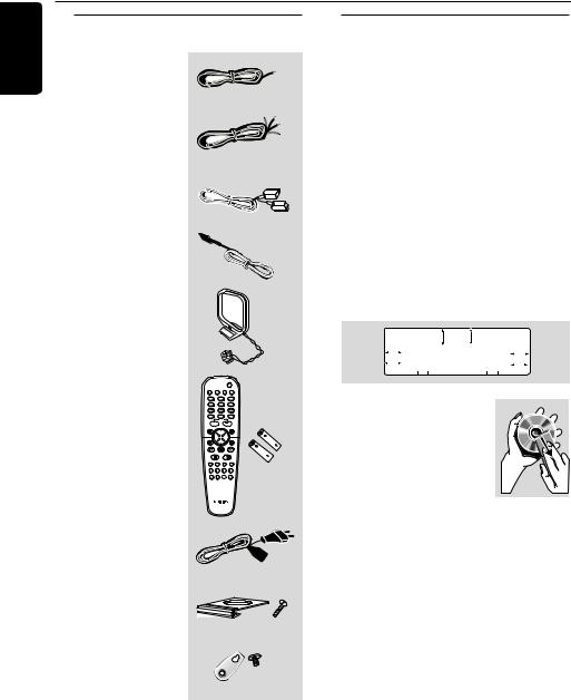
Supplied accessories
Surround/centre
 (3x)
(3x)
speaker cable
Front speaker and |
(2x) |
Subwoofer cables |
Scart cable (black)
FM wire antenna
MW loop antenna
DISC/
TV/AV MEDIA TUNER AUX/DI
1 |
2 |
3 |
4 |
5 |
6 |
7 |
8 |
9 |
SURR. |
0 |
SOUND |
|
VOL |
|
Remote control and
two batteries |
OK |
|
|
|
A-B |
AC power cable |
|
Mini speaker stands |
|
and screws |
(4x) (8x) |
Brackets and screws
(4x)
Care and safety information
Avoid high temperatures, moisture, water and dust
– Do not expose the system, batteries or discs to humidity, rain, sand or excessive heat (caused by heating equipment or direct sunlight.) Always keep the disc tray closed to avoid getting dust on the lens.
Avoid condensation problem
– The lens may cloud over when the player is suddenly moved from cold to warm surroundings, making it impossible to play a disc. Leave the player in the warm environment until the moisture evaporates.
Do not block the vents
– Do not operate the DVD system in an enclosed cabinet and allow about 10 cm
(4 inches) of free space all around the player for adequate ventilation.
10 cm (4 inches)
|
|
|
|
|
PHILIPS |
|
|
|
|
|
|
10 cm |
|
|
|
|
|
10 cm |
|||
(4 inches) |
|
|
DVD Home Cinema System |
|
|
(4 inches) |
||||
|
|
|
|
|
|
|
|
|
|
|
|
|
|
|
|
|
|
|
|
|
|
Care of disc
– To clean a CD, wipe it in a straight line from the centre towards the edge using a soft, lint-free cloth. Do not use
cleaning agent, as they may damage the disc!
– Write only on the printed
side of a CDR(W) and only with a soft felttipped pen.
– Handle the disc by its edge, do not touch the surface.
Care of the cabinet
– Use a soft cloth slightly moistened with a mild detergent solution. Do not use a solution containing alcohol, spirits, ammonia or abrasives.
Finding a suitable location
– Place the player on a flat, hard, stable surface.
8

Connections
Step 1: Set up the surround speakers
 screws


 mini speaker
  stand
stand
Step 2: Set up the front speakers with the subwoofer stands
front speaker
1
2
subwoofer stand
1 OR 2
1Before connecting the speakers to the DVD system, firmly attach the mini speaker stands to the surround speakers using the supplied screws.
OR
2Alternatively, you can choose to mount the speakers on the wall. Attach the supplied bracket firmly to the rear of speakers using the supplied screws. Then mount a screw (not supplied) on the wall where the speaker is to be hung and hook the speaker securely onto the mounted screw.
CAUTION!
You should get a qualified person to attach the brackets to the wall. DO NOT do it by yourself to avoid unexpected damage to the equipment or injury to personnel.
Note:
– The surround speakers are labelled as REAR L (left) or REAR R (right).
The connections between front speakers and DVD system are through the twin subwoofer stands.
1Attach the left front speaker to the left subwoofer stand and right front speaker to the right subwoofer stand.
2If you want to disconnect speaker from the subwoofer stand, press the button at the rear of subwoofer stand while pulling up the speaker.
Note:
– The front speakers are labelled as FRONT L (left) or FRONT R (right).
English
9
hsilgnE
Connections
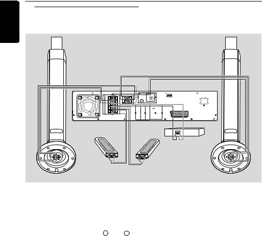
Step 3: Connecting speakers and twin subwoofer
front speaker |
front speaker |
with subwoofer |
with subwoofer |
stand (right) |
stand (left) |
SYSTEMSSPEAKER(8Ω) |
CENTERSURROUNDFRONT |
SR |
SUB-WOOFER |
|
L |
|
|
SCART OUT |
|
|
L |
|
L |
|
MW |
|
~ AC MAINS |
|
|
R |
|
R |
|
|
FM ANTENNA |
|
|
|
C |
|
|
|
AUDIO |
|
VIDEO |
|
|
SL |
|
DIGITAL |
AUX |
TV |
LINE |
OUT |
|
|
|
OUT |
IN |
IN |
OUT |
CVBS |
|
R
DIGITAL |
S-VIDEO |
IN |
|
Centre speaker
Surround speaker |
Surround speaker |
(right) |
(left) |
Connect the supplied speaker systems using the supplied speaker cables by matching the colours of the jacks and speaker cables. Fully insert the stripped portion of the speaker wire into the jacks.
Speakers / Subwoofer |
- |
+ |
Front Left (FL) (L) |
black |
white |
|
|
|
Front Right (FR) (R) |
black |
red |
Center (C) |
black |
green |
|
|
|
Surround Left (SL) |
black |
blue |
|
|
|
Surround Right (SR) |
black |
gray |
Subwoofer (L) |
black |
purple |
|
|
|
Subwoofer (R) |
black |
purple |
Notes:
–Ensure that the speaker cables are correctly connected. Improper connections may damage the system due to short-circuit.
–Do not connect more than one speaker to any one pair of +/- speaker jacks.
–Do not connect speakers with an impedance lower than the speakers supplied. Please refer to the SPECIFICATIONS section of this manual.
10
|
|
|
Connections |
|
|
|
|
|
Step 4: Placing the speakers |
|
Step 5: Connecting FM/MW |
|
and subwoofers |
|
antennas |
Centre speaker and DVD system
Front speaker |
2 |
|
|
|
Front speaker |
||||||
with subwoofer |
|
|
|
|
with subwoofer |
||||||
|
stand (Left) |
|
|
|
|
stand (Right) |
|||||
|
1 |
|
|
|
|
1 |
|
||||
|
|
|
|
|
|
|
|
|
|
|
|
|
|
|
|
|
|
|
|
|
|
|
|
|
|
|
|
|
|
|
|
|
|
|
|
|
|
|
|
|
|
|
|
|
|
|
|
|
|
|
|
|
|
|
|
|
|
|
|
3 |
3 |
Surround |
Surround |
Speaker |
Speaker |
(Left) |
(Right) |
|
|
FM |
MW |
antenna |
|
|
antenna |
|
|
1 |
|
fix the claw |
|
into the |
2 |
slot |
|
|
|
L |
|
|
|
|
|
|
|
R |
|
|
|
FM ANTENNA |
|
|
|
|
|
|
|
||
|
|
C |
|
|
AUDIO |
|
VIDEO |
|
|
|
DIGITAL |
AUX |
TV |
LINE |
OUT |
|
|
SL |
OUT |
IN |
IN |
OUT |
CVBS |
SYSTEMSSPEAKER(8Ω) |
SURROUNDCENTERFRONT |
SR |
WOOFERSUB- |
L |
|
|
|
|
|
|
|
||||
|
|
|
|
R |
|
|
|
|
|
|
DIGITAL |
|
|
|
S-VIDEO |
|
|
|
IN |
|
|
|
|
For best possible surround sound, all the speakers should be placed at the same distance from the listening position.
1Place the left and right front speakers with subwoofer stands at equal distances from the TV and at an angle of approximately 45 degrees from the listening position.
2Place the centre speaker above the TV or the DVD system so that the centre channel’s sound is localised.
3Place the surround speakers at normal listening ear level facing each other or mounted on the wall.
Notes:
–To avoid magnetic interference, do not position the front speakers too close to your TV.
–Allow adequate ventilation around the DVD system.
1Connect the supplied MW loop antenna to the MW jack. Place the MW loop antenna on a shelf or attach it to a stand or wall.
2Connect the supplied FM antenna to the FM jack. Extend the FM antenna and fix its ends to the wall.
For better FM stereo reception, connect an external FM antenna (not supplied).
MW
FM ANTENNA
Notes:
–Adjust the position of the antennas for optimal reception.
–Position the antennas as far as possible from your TV,VCR or other radiation source to prevent unwanted interference.
English
11
hsilgnE
Connections
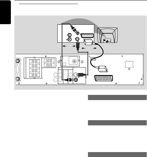
Step 6: Connecting TV
|
S-VIDEO |
AUDIO |
IN |
OUT |
SCART IN |
VIDEO IN 
OR
OR
SYSTEMSSPEAKER(8Ω) |
CENTERSURROUNDFRONT |
SR |
SUB-WOOFER |
|
|
|
Pb |
~ AC MAINS |
|
|
L |
|
|
MW |
|
|
|
|
|
R |
|
|
|
FM ANTENNA |
|
|
|
|
C |
|
|
AUDIO |
|
VIDEO |
|
|
|
|
DIGITAL |
AUX |
TV |
LINE |
OUT |
|
|
|
SL |
OUT |
IN |
IN |
OUT |
CVBS |
|
|
|
|
|
L |
|
|
|
SCART OUT |
|
|
|
|
|
|
|
|
|
|
|
|
|
R |
|
|
P-SCAN |
|
|
|
|
|
|
|
ON |
OFF |
|
|
|
|
DIGITAL |
|
|
|
S-VIDEO |
|
|
|
|
IN |
|
|
|
|
|
IMPORTANT!
–You only need to make one video connection from the following options, depending on the capabilities of your TV system.
–Connect the DVD system directly to the TV.
–Scart Video connection provides higher picture quality and S-Video connection provides better picture quality. These options must be available on your TV.
–If both Scart Video and S-Video connections are used to connect to your TV, the video signal will automatically switch to S-Video when you power up the DVD system. To set the VIDEO OUT(put) to ‘Scart’, see page 30.
Using Scart jack
●Use the scart video cable (black) to connect the DVD system’s SCART jack to the corresponding Scart input jacks on the TV.
OR
Using Composite Video jack (CVBS)
●Use the composite video cable (yellow - not supplied) to connect the DVD system’s CVBS jack to the video input jack (or labelled as A/V In, Video In, Composite or Baseband) on the TV.
OR
Using S-Video jack
●Use the S-video cable (not supplied) to connect the DVD system’s S-VIDEO OUT jack to the S-Video input jack (or labelled as Y/C or S-VHS) on the TV.
12
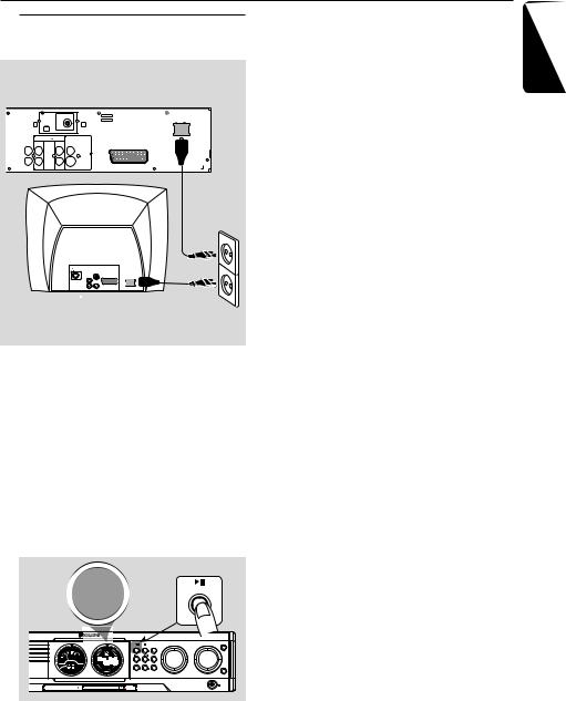
Step 7: Connecting the power cord
VOLTAGE SELECTOR ~ AC MAINS
|
|
MW |
|
|
|
|
|
|
FM ANTENNA |
|
|
|
|
|
|
110V |
220V |
|
|
AUDIO |
|
127V |
240V |
|
|
|
VIDEO |
|
|
DIGITAL |
AUX |
TV |
LINE |
OUT |
|
OUT |
IN |
IN |
OUT |
CVBS |
|
|
|
|
|
SCART OUT |
|
|
L |
|
|
|
|
|
R |
|
|
P-SCAN |
|
|
|
|
ON OFF |
|
|
DIGITAL |
|
|
|
S-VIDEO |
|
IN |
|
|
|
|
|
S-VIDEO
IN AUDIO 
OUT
~ AC MAINS
VIDEO IN
After everything is connected properly, plug in the AC power cord to the power outlet.
Never make or change any connections with the power switched on.
On the DVD system,
"AUTO INSTALL - PRESS PLAY" may appear on the display panel. Press ÉÅon the front panel to store all available radio stations or press Çto exit (see page 35 “Tuner Operations”).
AUTO INSTALL - PRESS PLAY |
PLAY• PAUSE |
|
|
||
|
|
TREBLE |
|
PLAY• PAUSE STOP SEATING SOURCE |
VOLUME |
|
RE |
|
|
R |
|
|
IGHT |
|
|
SEARCH SURROUND |
|
ISC CHANGER |
PROG TUNING CLOCK•TIMER |
|
|
SU |
|
|
R-L |
|
|
S |
|
|
|
BASS |
MEDIA SLOT |
EJECT |
|
Connections
English
13
hsilgnE
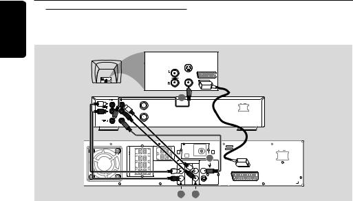
Connections (optional)
Connecting a VCR or
Cable/Satellite Box
S-VIDEO
IN
AUDIO
OUT
SCART IN
VIDEO IN
1 |
~ AC MAINS
ANT IN
|
VCR or |
TO TV |
Cable/Satellite Box |
SYSTEMSSPEAKER(8Ω) |
CENTERSURROUNDFRONT |
SR |
SUB-WOOFER |
L |
|
|
|
Pb |
SCART OUT |
|
|
L |
|
|
MW |
|
|
|
~ AC MAINS |
|
|
R |
|
|
|
FM ANTENNA |
3 |
|
|
|
|
C |
|
|
AUDIO |
|
VIDEO |
|
|
|
|
|
DIGITAL |
AUX |
TV |
LINE |
OUT |
|
|
|
|
SL |
OUT |
IN |
IN |
OUT |
CVBS |
|
|
|
|
|
|
R |
|
|
|
P-SCAN |
|
|
|
|
|
|
|
|
ON |
OFF |
|
|
|
|
DIGITAL |
|
|
|
S-VIDEO |
|
|
|
|
|
IN |
|
|
|
|
|
|
|
|
|
|
2 |
|
4 |
|
|
|
Viewing and listening to the playback |
|
Using the VCR for recording DVDs |
|
|
|
1Connect the VCR or Cable/Satellite Box to the TV as shown.
2Connect the DVD system’s AUX IN (R/L) jacks to the AUDIO OUT jacks on the VCR or cable/satellite box.
Before starting operation, press AUX/DI on the remote to select “AUX” in order to activate the input source.
Some DVDs are copy-protected. You cannot record or dub protected discs using a VCR.
3Connect the DVD system’s CVBS jack to the VIDEO IN jack on the VCR.
4Connect the DVD system’s LINE OUT (R/L) jacks to the AUDIO IN jacks on the VCR.
This will allow you to make analogue stereo (two channel, right and left) recordings.
To view DVD playback while recording, you must connect the DVD system to your TV using the SCART (as shown above) or the S-VIDEO connection.
14
 Loading...