


MP40-50 IntelliVue
Table of contents
 Loading...
M8000-9001F
1Table Of Contents
1 Basic Operation 1
Introducing the IntelliVue Family 1
IntelliVue MP20/MP20Junior/MP30 2
MP20/MP30 Major Parts and Keys 2
IntelliVue MP40/MP50 3
MP40/MP50 Major Parts and Keys 4
IntelliVue MP60/MP70 5
MP60/MP70 Major Parts and Keys 5
MP80/MP90 Major Parts and Keys 6
Remote Alarm Device 6
Docking Station 7
Related Products 7
Flexible Module Server (M8048A) 7
Measurement Modules 8
Multi-Measurement Server (M3001A) 9
Measurement Server Extensions 10
M3014A, M3015A and M3016A Capnography Extensions 10
M3012A Hemodynamic Measurement Server Extension 11
Operating and Navigating 12
Selecting Screen Elements 13
Using the Setup Menu 13
Using the Touchscreen 13
Disabling Touchscreen Operation 13
Using the SpeedPoint 14
Using the Navigation Point 15
Using a Mouse or Trackball 15
Using Keys 15
Permanent Keys 15
SmartKeys 16
Hardkeys 17
Pop-Up Keys 17
Using the On-Screen Keyboard 17
Using the On-Screen Calculator 18
Operating Modes 19
Standby Mode 19
Understanding Screens 20
Switching to a Different Screen 20
Changing a Screen’s Content 20
Using a Second Display 21
Using the Visitor Screen 21
Understanding Profiles 22
Swapping a Complete Profile 23
i

Swapping a Settings Block 23
Default Profile 23
Locked Profiles 23
Understanding Settings 24
Changing Measurement Settings 24
Switching a Measurement On and Off 24
Switching Numerics On and Off 25
Adjusting a Measurement Wave 25
Changing Wave Speeds 25
Changing the Wave Group Speed 25
Changing Wave Speed for a Channel 25
Freezing Waves 26
Freezing An Individual Wave 26
Freezing All Waves 26
Measuring Frozen Waves 26
Changing The Wave Speed 26
Updating The Frozen Wave 26
Releasing Frozen Waves 27
Using Labels 27
About Label Sets 27
Changing Measurement Labels (e.g. Pressure) 27
Resolving Label Conflicts 28
Changing Monitor Settings 29
Adjusting the Screen Brightness 29
Adjusting Touch Tone Volume 29
Setting the Date and Time 29
Checking Your Monitor Revision 29
Getting Started 30
Inspecting the Monitor 30
Switching On 30
Setting up the Measurement Servers and Modules 30
Starting Monitoring 30
Disconnecting from Power 31
Monitoring After a Power Failure 31
Networked Monitoring 31
Using Remote Applications 31
Remote Application Popup Keys 32
2 What’s New? 33
What’s New in Release C.0? 33
What’s New in Release B.1? 34
What’s New in Release B.0? 35
What’s New in Release A.2? 37
3 Alarms 39
Visual Alarm Indicators 40
ii

Audible Alarm Indicators 40
Alarm Tone Configuration 40
Traditional Audible Alarms (HP/Agilent/Philips/Carenet) 41
ISO/IEC Standard 9703-2 Audible Alarms 41
Changing the Alarm Tone Volume 41
Minimum Volume for No Central Monitoring INOP 41
Acknowledging Alarms 42
Acknowledging Disconnect INOPs 42
Alarm Reminder (ReAlarm) 42
Pausing or Switching Off Alarms 42
To Pause All Alarms 43
To Switch All Alarms Off 43
To Switch Individual Measurement Alarms On or Off 43
While Alarms are Paused or Off 43
Restarting Paused Alarms 44
Resetting Arrhythmia Alarm Timeouts 44
Extending the Alarm Pause Time 44
Alarm Limits 44
Viewing Individual Alarm Limits 44
Viewing All Alarm Limits 45
Changing Alarm Limits 46
About Automatic Alarm Limits (AutoLimits) 47
Documenting Alarm Limits 47
Reviewing Alarms 48
Alarm Messages Window 48
Review Alarms Window 48
Understanding Alarm Messages 49
Latching Alarms 49
Viewing the Alarm Latching Settings 49
Alarm Latching Behavior 50
Silencing Latched Alarms from an Information Center 50
Testing Alarms 50
Alarm Behavior at On/Off 50
4 Patient Alarms and INOPs 51
Patient Alarm Messages 51
Technical Alarm Messages (INOPs) 57
5 Managing Patients 75
Admitting a Patient 75
Patient Category and Paced Status 76
Admitting a Centrally-Monitored Patient 76
Quick Admitting a Patient 76
Editing Patient Information 77
Discharging a Patient 77
Transferring Patients 78
iii

Transferring a Centrally-Monitored Patient 78
Transferring a Patient with an MMS (no Central Station) 79
Data Upload from an MMS 79
Data Exchange Between Information Centers 80
Resolving Patient Information Mismatch 80
Manually Resolving Patient Mismatch 80
Patient Mismatch - If One Set of Patient Data is Correct 81
Patient Mismatch - If Neither Patient Data Set is Correct 81
Patient Mismatch - If Both Patient Data Sets Are Correct 82
Automatically Resolving Patient Mismatch 82
Care Groups 82
Understanding the Care Group Overview Bar 83
Viewing the My Care Group Window 84
Viewing the Other Bed Window 85
Other Bed Pop-Up Keys 86
Visual Alarm Status Information in the Other Bed Window 86
Care Group Alarms 86
Telemetry Data Overview 87
Unpairing a Telemetry Device 87
Telemetry Data Overview Screen Element 87
Silencing Telemetry Alarms from the Bedside 88
Suspending Telemetry Alarms 88
Using Standby 88
6 ECG, Arrhythmia, and ST Monitoring 89
Skin Preparation for Electrode Placement 89
Connecting ECG Cables 89
Selecting the Primary and Secondary ECG Leads 90
Checking Paced Status 90
Understanding the ECG Display 91
Monitoring Paced Patients 91
Setting the Paced Status (Pace Pulse Rejection) 92
Avoiding Pace Pulse Repolarization Tails 92
Changing the Size of the ECG Wave 92
To Change the Size of an Individual ECG Wave 92
To Change the Size of all the ECG Waves 93
Changing the Volume of the QRS Tone 93
Changing the ECG Filter Settings 93
Choosing EASI or Standard Lead Placement 94
About ECG Leads 94
ECG Leads Monitored 94
Changing Lead Sets 94
ECG Lead Fallback 95
ECG Lead Placements 95
Standard 3-Lead Placement 96
Standard 5-Lead Placement 96
iv

Chest Electrode Placement 97
10-Lead Placement 98
Conventional 12-Lead ECG 98
Modified 12-Lead ECG 99
Choosing Standard or Modified Electrode Placement 99
Labelling 12-Lead ECG Reports 99
Capture 12-Lead 100
EASI ECG Lead Placement 100
ECG, Arrhythmia, and ST Alarm Overview 102
Using ECG Alarms 103
Extreme Alarm Limits 103
ECG Alarms Off Disabled 103
HR Alarms When Arrhythmia Analysis is Switched Off 103
HR Alarms When Arrhythmia Analysis is Switched On 103
ECG Safety Information 103
About Arrhythmia Monitoring 105
Arrhythmia Options 105
Where Can I Find More Information? 105
Switching Arrhythmia Analysis On and Off 106
Choosing an ECG Lead for Arrhythmia Monitoring 106
Aberrantly-Conducted Beats 106
Atrial Fibrillation and Flutter 106
Intermittent Bundle Branch Block 107
Understanding the Arrhythmia Display 107
Viewing Arrhythmia Waves 107
Arrhythmia Beat Labels 107
Arrhythmia Status Messages 108
Rhythm Status Messages 108
Ectopic Status Messages 109
Arrhythmia Relearning 109
Initiating Arrhythmia Relearning Manually 109
Automatic Arrhythmia Relearn 110
Arrhythmia Relearn and Lead Fallback 110
Arrhythmia Alarms 110
Yellow Arrhythmia Alarms 111
Arrhythmia Alarms and Latching 111
Switching Individual Arrhythmia Alarms On and Off 111
Switching All Yellow Arrhythmia Alarms On or Off 111
Adjusting the Arrhythmia Alarm Limits 111
Arrhythmia Alarm Timeout Periods 111
What is a Timeout Period? 112
Resetting the Timeout Period 112
How are Yellow Arrhythmia Alarms Indicated? 112
Behavior of Unsilenced Arrhythmia Alarms 112
Behavior of Silenced Arrhythmia Alarms 112
Arrhythmia Alarm Chaining 113
v

Understanding PVC-Related Alarms 114
About ST Monitoring 115
Switching ST On and Off 115
Selecting ST Leads for Analysis 115
Understanding the ST Display 116
Updating ST Baseline Snippets 117
Recording ST Segments 117
About the ST Measurement Points 118
Adjusting ST Measurement Points 118
ST Alarms 120
Single- or Multi-lead ST Alarming 120
Changing ST Alarm Limits 120
Viewing ST Maps 120
Current View 120
Tre n d V i ew 121
Viewing an ST Map 122
Working in the ST Map Task Window 122
Switching Between ST Map Views 122
Displaying an ST Reference Baseline 123
Updating an ST Map Reference Baseline 123
Changing the Scale of the ST Map 123
Changing the Trending Interval 123
Printing an ST Map Report 123
7 Monitoring Pulse Rate 125
Entering the Setup Pulse Menu 125
System Pulse Source 125
Switching Pulse On and Off 126
Using Pulse Alarms 126
Selecting the Active Alarm Source: HR or Pulse? 126
Alarm Source Selection Disabled 127
Changing HR/Pulse Alarm Limits 127
Extreme Alarm Limits 127
QRS Tone 127
8 Monitoring Respiration Rate (Resp) 129
Lead Placement for Monitoring Resp 129
Optimizing Lead Placement for Resp 129
Cardiac Overlay 129
Lateral Chest Expansion 130
Abdominal Breathing 130
Understanding the Resp Display 130
Changing Resp Detection Modes 130
Auto Detection Mode 130
Manual Detection Mode 131
Resp Detection Modes and Cardiac Overlay 131
vi

Changing the Size of the Respiration Wave 131
Changing the Speed of the Respiration Wave 131
Using Resp Alarms 132
Changing the Apnea Alarm Delay 132
Resp Safety Information 132
9 Monitoring SpO
2
SpO2 Sensors 133
Applying the Sensor 133
Connecting SpO2 Cables 134
Measuring SpO
2
134
Assessing a Suspicious SpO2 Reading 135
Understanding SpO2 Alarms 136
Adjusting the Alarm Limits 136
Adjusting the Desat Limit Alarm 136
Pleth Wave 136
Perfusion (Pleth) Indicator 137
Setting SpO2/Pleth as Pulse Source 137
Setting Up Tone Modulation 137
Setting the QRS Volume 137
Calculating SpO2 Difference 137
10 Monitoring NBP 139
Introducing the Oscillometric NBP Measurement 139
Measurement Limitations 140
Measurement Methods 140
Reference Method 140
Preparing to Measure NBP 140
Correcting the Measurement if Limb is not at Heart Level 141
Understanding the NBP Numerics 141
Starting and Stopping Measurements 142
Enabling Automatic Mode and Setting Repetition Time 142
Choosing the NBP Alarm Source 143
Assisting Venous Puncture 143
Calibrating NBP 143
133
11 Monitoring Temperature 145
Making a Temp Measurement 145
Selecting a Temperature for Monitoring 145
Extended Temperature Label Set 146
Calculating Temp Difference 146
12 Monitoring Invasive Pressure 147
Setting up the Pressure Measurement 147
Selecting a Pressure for Monitoring 148
Extended Pressure Label Set 148
vii

Zeroing the Pressure Transducer 148
Zeroing ICP (or IC1/IC2) 149
Determining a Pressure’s Most Recent Zero 149
Zeroing a Pressure Measurement 149
Using the Zero Hardkey 149
Zeroing All Pressures Simultaneously 150
Troubleshooting the Zero 150
Adjusting the Calibration Factor 150
Displaying a Mean Pressure Value Only 150
Changing the Pressure Wave Scale 151
Optimizing the Waveform 151
Non-Physiological Artifact Suppression 151
Choosing the Pressure Alarm Source 151
Calibrating Reusable Transducer CPJ840J6 152
Making the Pressure Calibration 152
Troubleshooting the Pressure Calibration 153
Calculating Cerebral Perfusion 153
Calculating Pulse Pressure Variation 153
Measuring Pulmonary Artery Wedge Pressure 154
Editing the Wedge 155
Identifying the Pressure Analog Output Connector 155
13 Monitoring Cardiac Output 157
Hemodynamic Parameters 158
Using the C.O. Procedure Window 159
Accessing the Setup C.O. and Setup CCO Menus 160
Entering the HemoCalc Window 160
Measuring C. O. Using the PiCCO Method 160
Measuring Continuous Cardiac Output 160
Measuring Systemic Vascular Resistance 160
Setting Up the PiCCO C.O. Measurement 161
Performing PiCCO C.O. Measurements 162
Editing PiCCO C.O. Measurements 162
Saving and Calibrating PiCCO C.O. Measurements 163
CCO Calibration Status Indicators 163
Measuring C.O. Using the Right Heart Thermodilution Method 164
Setting up RH C.O. Measurements 164
Ice-Bath Setup for RH Thermodilution C.O. Measurements 164
Setting the Computation Constant 165
Performing RH C.O. Measurements 165
Editing and Saving RH C.O. Measurements 165
Documenting C.O. Measurements 165
C.O. Injectate Guidelines 166
Guidelines for Right Heart Thermodilution C.O. Injectate 166
Guidelines for PiCCO C.O. Injectate 166
Injectate Volume, Patient Weight and ETVI Values (PiCCO Only) 166
viii

C.O./CCO Curve Alert Messages 167
C.O./CCO Prompt Messages 168
C.O./CCO Warning Messages 169
C.O./CCO Safety Information 169
14 Monitoring Carbon Dioxide 171
Using the Capnography Extension (M3014A) 172
Preparing to Measure Mainstream CO
Attaching and Removing the CO2 Sensor 172
Zeroing the CO2 Sensor 173
2
Using the Mainstream CO2 Extension (M3016A) 174
Preparing to Measure Mainstream CO
Checking Transducer Accuracy 174
Calibrating the Transducer 175
Attaching and Removing the CO2 Tra n s d u c e r 175
2
Using the Microstream CO2 Extension (M3015A) 176
Preparing to Measure Microstream CO2 176
Setting up Microstream CO2 Measurements 176
Using Microstream Accessories 176
Using the FilterLine and Airway Adapter 177
Removing Exhaust Gases from the System 177
Suppressing Zero Calibration 177
Suppressing Sampling 178
Setting up Mainstream and Microstream 178
Adjusting the CO2 Wave S c ale 178
Setting up CO2 Corrections 178
Changing CO2 Alarms 179
Changing the Apnea Alarm Delay 179
Deriving Alarms From awRR 180
Changing awRR Alarm Limits 180
172
174
15 Monitoring tcGas 181
Identifying tcGas Module Components 181
Setting the tcGas Sensor Temperature 182
Using the tcGas Site Timer 182
Setting the tcGas Site Timer 182
Restarting the tcGas SiteTimer 183
Disabling the tcGas Site Timer 183
Setting the tcGas Barometric Pressure 183
Remembraning the tcGas Transducer 183
New/Dried Out Transducers 184
Storing tcGas Transducers 184
Calibrating the tcGas Transducer 185
Calibration Failure 186
Troubleshooting tcGas Calibration 186
Applying the tcGas Transducer 187
ix

Selecting the tcGas HeatPowerDisplay Mode 188
Zeroing the tcGas Relative Heat Power 188
Finishing tcGas Monitoring 188
TcGas Corrections 188
Temperature Correction for tcpCO
Metabolism Correction for tcpCO
2
2
188
188
16 Monitoring SvO
Preparing to Monitor SvO
2
2
190
Carrying out a Pre-insertion Calibration 190
Inserting the Catheter 191
Performing a Light Intensity Calibration 191
Performing In-Vivo Calibration 192
Setting Up the In-Vivo Calibration 192
Making the In-Vivo Calibration 192
Calculating Oxygen Extraction 192
17 Monitoring EEG 193
EEG Monitoring Setup 194
Using the EEG Impedance/Montage Window 194
Choosing an EEG Electrode Montage 195
Changing the Impedance Limit 195
About Electrode-to-Skin Impedance 196
Impedance Indicators 196
About Compressed Spectral Arrays (CSA) 197
Displaying CSAs 198
Changing EEG Settings 198
Switching EEG Numerics On and Off 198
Changing the Scale of the EEG Waves for Display 198
Changing Filter Frequencies 199
Changing the Speed of the EEG Wave 199
EEG Reports 199
EEG Safety Information 200
EEG and Electrical Interference 200
189
18 Monitoring BIS 201
BIS Monitoring Setup 202
Monitoring BIS Using the DSC and BIS Engine 202
Monitoring BIS using the BISx 203
Manufacturer’s Information 204
BIS Continuous Impedance Check 204
BIS Cyclic Impedance Check 204
Starting a Cyclic Impedance Check 204
Stopping a Cyclic Impedance Check 204
BIS Window 205
BIS Impedance Indicators 205
x

Changing the BIS Smoothing Rate 206
Switching BIS and Individual Numerics On and Off 206
Changing the Scale of the EEG Wave 206
Switching BIS Filters On or Off 206
BIS Safety Information 207
19 Trends 209
Viewing Trends 209
Viewing Graphic Trends 210
Viewing Vital Signs Trends 210
Tre n ds Po p - U p K e y s 211
Setting Up Trends 211
Making Segment Settings 212
Expanded View 212
Trend Scales for Segment Measurements 212
Optimum Scale 212
Tr e n d Gr o u p 2 1 2
No. of Segments 212
Tre n d Gr o u p s 213
Tre n d I n te r v a l 213
Tre n d Pr i o r i t y 213
Trend Parameter Scales 213
Graphical Trend Presentation 214
Documenting Trends 214
Trends Databases 215
Aperiodic Trends Database 215
Trending Multiple-Value Measurements 215
Screen Trends 215
Setting the Screen Trend Time 216
Changing the Selection of Screen Trends Displayed 217
Activating the Cursor for Screen Trends 217
Changing the Screen Trend View 217
Tabular View 217
Horizon View 218
Setting the Horizon 218
Setting the Horizon Trend Scale 218
20 Calculations 219
Viewing Calculations 219
Calculations Windows 220
Calculations Pop-Up Keys 220
Reviewing Calculations 221
Performing Calculations 221
Entering Values for Calculations 222
Automatic Value Substitution 222
Automatic Unit Conversion 222
xi

Manual Unit Conversion 222
BSA Formula 222
Documenting Calculations 223
21 High Resolution Trend Waves 225
Changing the Hi-Res Trend Waves Displayed 225
Hi-Res Trend Wave Scales 225
Hi-Res Trend Waves and OxyCRG 225
Printing Hi-Res Trend Wave Reports 226
Hi-Res Trend Wave Recordings 226
22 Event Surveillance 227
Levels of Event Surveillance 227
Event Groups 228
Event Episodes 228
Events Pop-Up Keys 229
Event Triggers 230
Event Retriggering 231
Event Notification 231
Setting Triggers for NER and Basic Event Surveillance 231
Setting Triggers and Notification for Advanced Event Surveillance 232
Triggering Events Manually 233
The Events Database 233
Viewing Events 233
Event Counter 233
Counting Combi-Events 234
Counting Neonatal Event Review (NER) Events 234
Event Summary Window 235
Event Review Window 235
Event Episode Window 236
Annotating Events 237
Documenting Events 237
Documenting Event Review 237
Documenting an Event Episode 238
Event Recordings 238
Event Review Recordings 238
Event Episode Recordings 239
Event Reports 239
Event Review Reports 240
Event Episode Reports 241
Event Summary Reports 241
23 Using Timers 243
Viewing Timers 243
Notification 243
Timer Types 244
xii

Timer Setup Pop-up Keys 244
Setting Up Timers 244
Timer Label 244
Run Time 245
Timer Counting Direction 245
Displaying Timers On The Main Screen 245
Main Screen Timer Pop-up Keys 246
Displaying A Clock On The Main Screen 246
24 Recording 247
Starting and Stopping Recordings 248
Quickstarting Recordings 248
Extending Recordings 249
Stopping Recordings 249
Recording Without a Template 249
Overview of Recording Types 249
All ECG Waves Recordings 250
Creating and Changing Recordings Templates 250
Changing ECG Wave Gain 251
Recording Priorities 252
Sample Recording Strip 252
Recording Strip Code 252
Recorded Waveforms 253
Maintaining Recording Strips 253
Reloading Paper 254
Recorder Status Messages 255
25 Printing Patient Reports 257
Starting Reports Printouts 257
Stopping Reports Printouts 258
Setting Up Reports 258
Setting Up ECG Reports 258
Setting Up Vital Signs and Graphic Trend Reports 259
Setting Up Auto Reports 259
Setting Up Individual Print Jobs 260
Checking Printer Settings 260
Switching Printers On Or Off for Reports 261
Dashed Lines on Reports 261
Unavailable Printer: Re-routing Reports 261
Printer Status Messages 262
Sample Report Printouts 262
Alarm Limits Report 263
Realtime Report 264
Cardiac Output Report 265
ECG Reports 266
Other Reports 266
xiii

26 Using the Drug Calculator 267
Accessing the Drug Calculator 267
Performing Drug Calculations 268
About the Rule of Six 268
Performing Calculations for a Non-Specific Drug 268
Performing Calculations for a Specific Drug 269
Charting Infusion Progress 270
Using the Titration Table 270
Documenting Drug Calculations 270
27 VueLink Modules 271
Connecting an External Device 272
Changing VueLink Waves and Numerics Displayed 272
Viewing the VueLink Device Data Window 272
Using VueLink Screens 273
Switching VueLink On and Off 273
Alarms/INOPs From External Devices 273
Language Conflict with External Device Drivers 274
28 Respiratory Loops 275
Viewing Loops 275
Capturing and Deleting Loops 276
Showing/Hiding Loops 276
Changing Loops Display Size 277
Using the Loops Cursor 277
Changing Loops Type 277
Source Device 277
Documenting Loops 278
29 Care and Cleaning 279
General Points 279
Cleaning 280
Disinfecting 280
Cleaning Monitoring Accessories 280
Sterilizing 281
Cleaning the Recorder Printhead (M1116B only) 281
Cleaning the Batteries and Battery Compartment 281
30 Using the Batteries 283
Battery Power Indicators 284
Battery LED 284
Battery Status on the Main Screen 284
Battery Status Window 286
Viewing Individual Battery Status 286
Recording Battery Status 286
xiv

Printing Battery Reports 286
Checking Battery Charge 286
Replacing Batteries 287
Optimizing Battery Performance 287
Display Brightness Setting 288
Charging Batteries 288
Conditioning Batteries 288
Unequally-Charged Batteries 288
Battery Safety Information 289
31 Maintenance and Troubleshooting 291
Inspecting the Equipment and Accessories 291
Inspecting the Cables and Cords 291
Maintenance Task and Test Schedule 292
Troubleshooting 293
Disposing of the Monitor 293
Disposing of Empty Calibration Gas Cylinders 293
32 Accessories 295
ECG/Resp Accessories 295
Tr u nk C a b l e s 295
3-Electrode Cable Sets 295
5-Electrode Cable Sets 296
10-Electrode Cable Sets 296
3-Electrode One Piece Cables 296
5-Electrode One Piece Cables 296
Set Combiners and Organizers 297
NBP Accessories 297
Adult/Pediatric Multi-Patient Comfort Cuffs and Disposable Cuffs 297
Reusable Cuff Kits 297
Adult/Pediatric Antimicrobial Coated Reusable cuffs 298
Adult/Pediatric Soft Single Patient Single-Hose Disposable Cuffs 298
Neonatal/Infant Cuffs (Disposable, non-sterile) 298
Invasive Pressure Accessories 299
SpO2 Accessories 299
Temperature Accessories 303
Cardiac Output (C.O.) Accessories 304
Mainstream CO2 Accessories (for M3014A) 304
Mainstream CO2 Accessories (for M3016A) 305
Microstream CO2 Accessories 306
tcGas Accessories 306
EEG Accessories 307
BIS Accessories 307
BIS Sensors 307
Other BIS Accessories 308
SvO2 Accessories 308
xv

Recorder Accessories 309
33 Installation and Specifications 311
Intended Use 311
Indication for Use 311
Manufacturer’s Information 312
BIS Manufacturer’s Information 312
Responsibility of the Manufacturer 312
Trademark Acknowledgement 313
Symbols 314
Installation Safety Information 315
Connectors 315
MP20/MP30 316
MP40/MP50 317
MP60/MP70 318
MP80/MP90 320
Altitude Setting 321
Monitor Safety Specifications 321
Physical Specifications 322
Environmental Specifications 323
M4605A Battery Specifications 326
Monitor Performance Specifications 326
Measurement Specifications 332
ECG/Arrhythmia/ST 332
Respiration 334
SpO
2
NBP 336
Invasive Pressure and Pulse 337
Te m p 339
CO
2
Cardiac Output / Continuous Cardiac Output 341
tcGas 342
SvO
2
EEG 343
BIS 344
Safety and Performance Tests 345
Electromagnetic Compatibility (EMC) Specifications 345
Accessories Compliant with EMC Standards 345
Electromagnetic Emissions 345
Avoiding Electromagnetic Interference (Resp and BIS) 345
Electromagnetic Immunity 346
Recommended Separation Distance 346
Recommended separation distances from portable and mobile RF communication equipment347
Electrosurgery Interference/Defibrillation/Electrostatic Discharge 348
Fast Transients/Bursts 348
Restart time 348
334
339
343
xvi

34 Default Settings Appendix 349
Alarm Default Settings 350
ECG, Arrhythmia, and ST Default Settings 350
Pulse Default Settings 353
Respiration Default Settings 354
SpO2 Default Settings 354
NBP Default Settings 355
Temperature Default Settings 355
Invasive Pressure Default Settings 356
Cardiac Output Default Settings 357
CO2 Default Settings 358
tcGas Default Settings 358
SvO2 Default Settings 359
EEG Default Settings 359
BIS Default Settings 359
VueLink Default Settings 360
xvii

xviii

1
1Basic Operation
These Instructions for Use are for clinical professionals using the IntelliVue MP20/MP30 (M8001A/
M8002A), MP40/50 (M8003A/M8004A) and MP60/70/80/90 (M8005A/M8007A/M8008A/
M8010A) patient monitors.Unless otherwise specified, the information here is valid for all the above
IntelliVue patient monitors.
The basic operation section gives you an overview of the monitor and its functions. It tells you how to
perform tasks that are common to all measurements (such as entering data, switching a measurement
on and off, setting up and adjusting wave speeds, working with profiles). The alarms section gives an
overview of alarms. The remaining sections tell you how to perform individual measurements, and how
to care for and maintain the equipment.
Familiarize yourself with all instructions including warnings and cautions before starting to monitor
patients. Read and keep the Instructions for Use that come with any accessories, as these contain
important information about care and cleaning that is not repeated in this book.
This guide describes all features and options. Your monitor may not have all of them; they are not all
available in all geographies. Your monitor is highly configurable. What you see on the screen, how the
menus appear and so forth, depends on the way it has been tailored for your hospital and may not be
exactly as shown here.
In this guide:
•A warning alerts you to a potential serious outcome, adverse event or safety hazard. Failure to
observe a warning may result in death or serious injury to the user or patient.
•A caution alerts you to where special care is necessary for the safe and effective use of the product.
Failure to observe a caution may result in minor or moderate personal injury or damage to the
product or other property, and possibly in a remote risk of more serious injury.
• Monitor refers to the entire patient monitor. Display refers to the physical display unit. Display
Screen and Screen refer to everything you see on monitor’s display, such as measurements, alarms,
patient data and so forth.
Introducing the IntelliVue Family
The Philips IntelliVue family of patient monitors offers a monitoring solution optimized for the
surgical, cardiac, medical and neonatal care environments. Combining patient surveillance and data
management, it allows multi-measurement monitoring by linking separate modules with “plug-andplay” convenience.
1
1 Basic Operation Introducing the IntelliVue Family
1
4
5
6
7
3
Your monitor stores data in trend, event, and calculation databases. You can see tabular trends (vital
signs) and document them on a local or remote printer. You can view measurement trend graphs, with
up to three measurements combined in each graph, to help you identify changes in the patient’s
physiological condition. You can view fast-changing measurement trends with beat to beat resolution
and see up to four high resolution trend segments. Event surveillance enhances documentation and
review of physiologically significant events by automatically detecting and storing up to 50 userdefined clinical events over a 24 hour period.
There is a choice of monitor configurations, as explained below. All models can also use computer
devices such as a mouse, a trackball and a keyboard.
IntelliVue MP20/MP20
The IntelliVue MP20/MP20Junior/MP30 (M8001A/
M8002A) patient monitor has a 10-inch TFT LCD
flat panel SVGA display. The standard input devices
for the MP30 are the Touchscreen and integrated
navigation point; the MP20 is supplied with an
integrated navigation point only. Up to six waves can
be shown on MP20/MP30 Screens (USA - up to four
waves, MP20Junior - up to 3 waves). 12 ECG traces
can be shown on the 12-Lead ECG Screen.
The MP20/MP30 can be connected to one MultiMeasurement Server (MMS) and any one of the
measurement server extensions. There is an optional
built-in recorder. The Flexible Module Server
(M8048A) and all plug-in modules cannot be used
with the MP20/MP30. With an optional Interface
board Bispectral Index (BIS) monitoring is possible.
MP20Junior is an option of MP20 (M8001A) and is
not referred to separately in these Instructions for Use.
Junior
/MP30
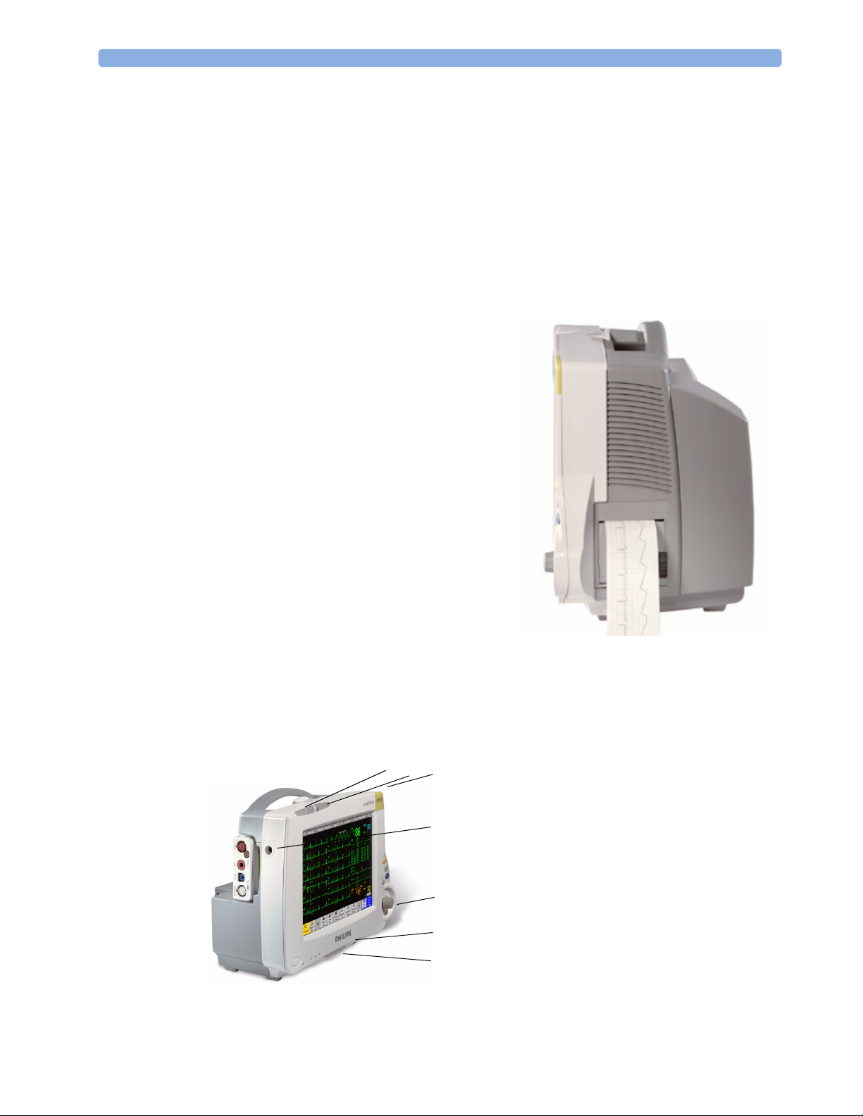
MP20/MP30 Major Parts and Keys
MP20/MP30 left side
12
2
3
4
5
6
7
1 Color-coded alarm lamps
2 Alarms off lamp
3 Model indicator
4 ECG out
5 Navigation Point
6 Part number and serial number
7 Mounting quick-release lever
2
Introducing the IntelliVue Family 1 Basic Operation
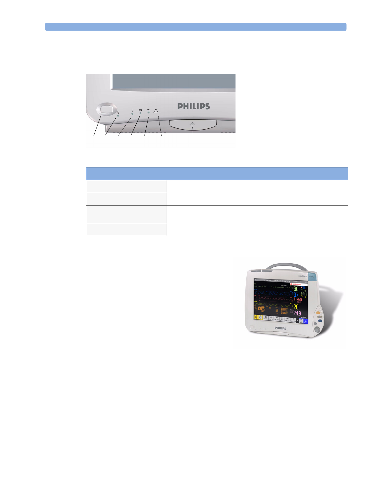
MP20/MP30 front panel
1
On/Standby switch
2
On/Standby LED
3
Error LED
4
Battery status LED
5
AC power operation LED
6 “read the documentation”
symbol
7
Mounting quick-release lever
123 4 5 67
MP20/MP30 LED Colors and their Meanings
On/Standby LED
Error LED
Battery LED
AC Power LED
IntelliVue MP40/MP50
The IntelliVue MP40/MP50 (M8003A/M8004A)
patient monitor has a 12-inch TFT LCD flat panel
SVGA display. The standard input devices for the MP50
are the Touchscreen and integrated navigation point; the
MP40 is supplied with an integrated navigation point
only. Up to six waves can be shown on MP40/MP50
Screens, 12 ECG traces can be shown on the 12-Lead
ECG Screen.
The MP40/MP50 can be connected to one MultiMeasurement Server (MMS) and any one of the
measurement server extensions. The IntelliVue family
plug-in measurement modules can be connected to its
four integrated plug-in module slots with plug-and-play convenience (the only exception is the SvO
module, M1021A, which cannot be used with the MP40/MP50). The Flexible Module Server
(M8048A) cannot be used with the MP40/MP50.
Green when monitor is switched on
Red if there is a problem with the monitor
Green, yellow, and red.
See the section on Using the Batteries for details
Green while the monitor is connected to AC power (mains)
2
3
1 Basic Operation Introducing the IntelliVue Family
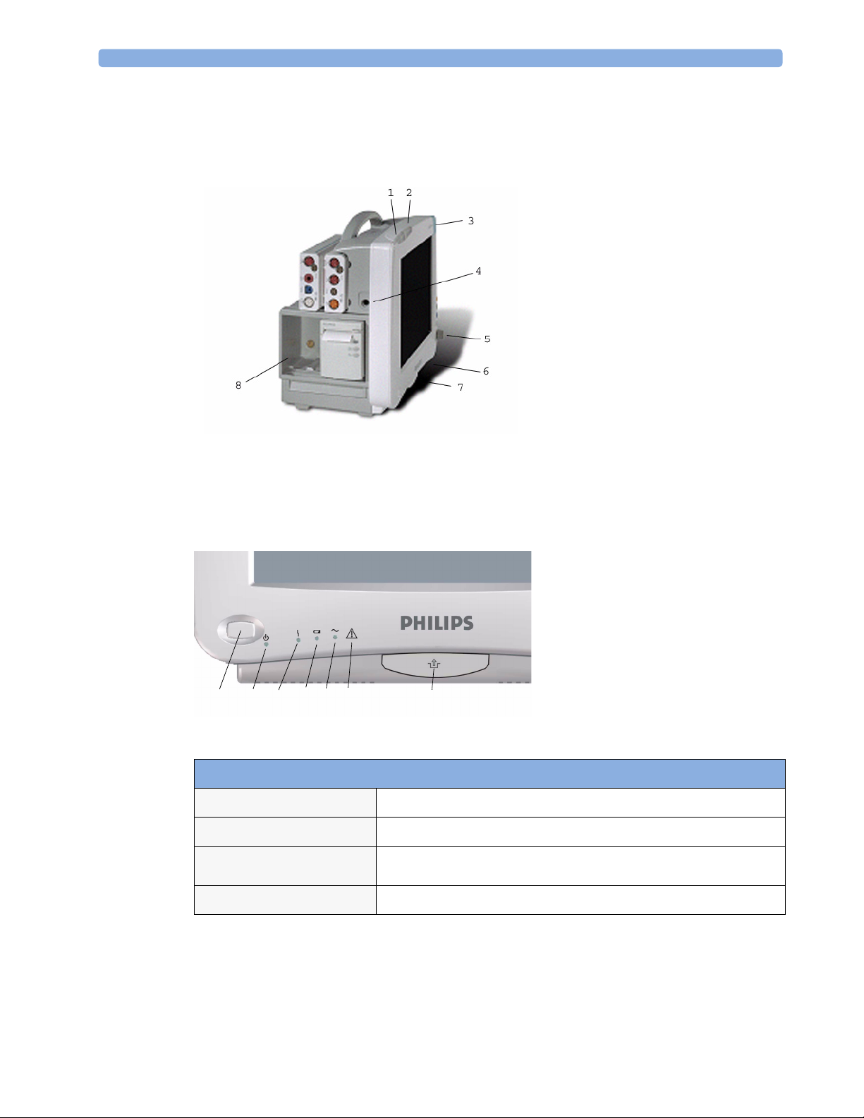
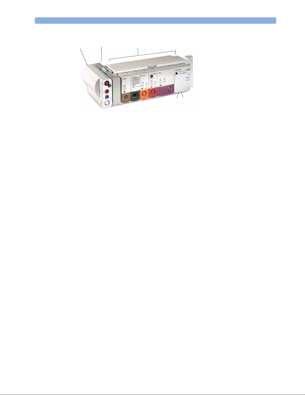
MP40/MP50 Major Parts and Keys
MP40/MP50 left side
1 Color-coded alarm lamps
2 Alarms off lamp
3 Model indicator
4 ECG out
5 Navigation Point
6 Part number and serial number
7 Mounting quick-release lever
8 Plug-in module slots
MP40/MP50 front panel
1
456 7
32
MP40/MP50 LED Colors and their Meanings
On/Standby LED
Error LED
Battery LED
AC Power LED
Green when monitor is switched on
Red if there is a problem with the monitor
Green, yellow, and red.
See the section on Using the Batteries for details
Green while the monitor is connected to AC power (mains)
1
On/Standby switch
2
On/Standby LED
3
Error LED
4
Battery status LED
5
AC power operation LED
6 “read the documentation”
symbol
7
Mounting quick-release lever
4

Introducing the IntelliVue Family 1 Basic Operation
IntelliVue MP60/MP70
The IntelliVue MP60/MP70 (M8005A/M8007A) patient monitors integrate the display unit, with a
15” color LCD display, and the data processing unit into one. Up to eight waves can be shown on the
screens, as well as the 12-Lead ECG Screen. The MP60 uses the SpeedPoint as its primary input device
while the MP70 uses touch screen operation but may have an optional SpeedPoint.
The monitors can be connected to the Multi-Measurement Server (MMS) and any one of the
measurement server extensions, and to the Flexible Module Server (M8048A). The IntelliVue family
plug-in measurement modules can be connected to its FMS module slots with plug-and-play
convenience.
The MP60/MP70 has two integrated slots for plug-in modules. You can combine one each of the
following modules in these slots: Pressure, Temperature, C.O., SpO
the two-slot recorder module in the integrated slots.
and VueLink. You can also use
2
MP60/MP70 Major Parts and Keys
1 Color coded alarm lamps
1
2
891011 7
3
6
4
5
2 Alarms Off lamp
3Display
4Model indicator
5 SpeedPoint (optional for MP70)
6 Part number and serial number
7 Mounting quick-release lever
8AC power LED
9Error LED
10 Power on/standby switch
11 Power on LED
5
1 Basic Operation Introducing the IntelliVue Family
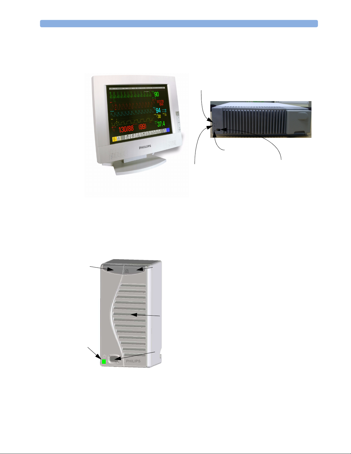
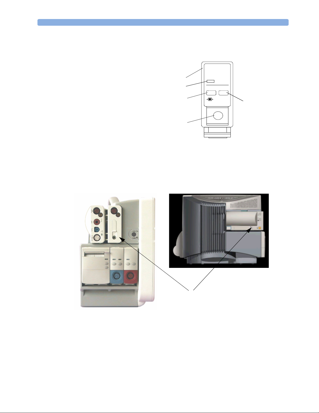
MP80/MP90 Major Parts and Keys
In the MP80 and MP90, the display and the processing unit are separate components. They offer both
touchscreen and the Remote SpeedPoint as standard input devices.
AC Power LED
Power on LED
Display Unit
Remote Alarm Device
The Remote Alarm Device provides audio and visual indicators of alarms, in addition to those shown
on the display.
1
5
Error LED
Processing Unit
2
1 Two color coded alarm lamps (right-hand lamp flashes
red or yellow for patient alarms, left-hand lamp flashes
light blue for INOPs)
2 Alarms off lamp - when illuminated it indicates that all
alarms are deactivated.
3
4
3 Speaker - for alarm prompts, QRS tones and so forth
4 Monitor power on /standby switch. Press to switch
monitor on remotely. Press and hold for one second to
turn monitor off.
5 Power on LED - green when monitor is on
Power on Switch
6
Related Products 1 Basic Operation
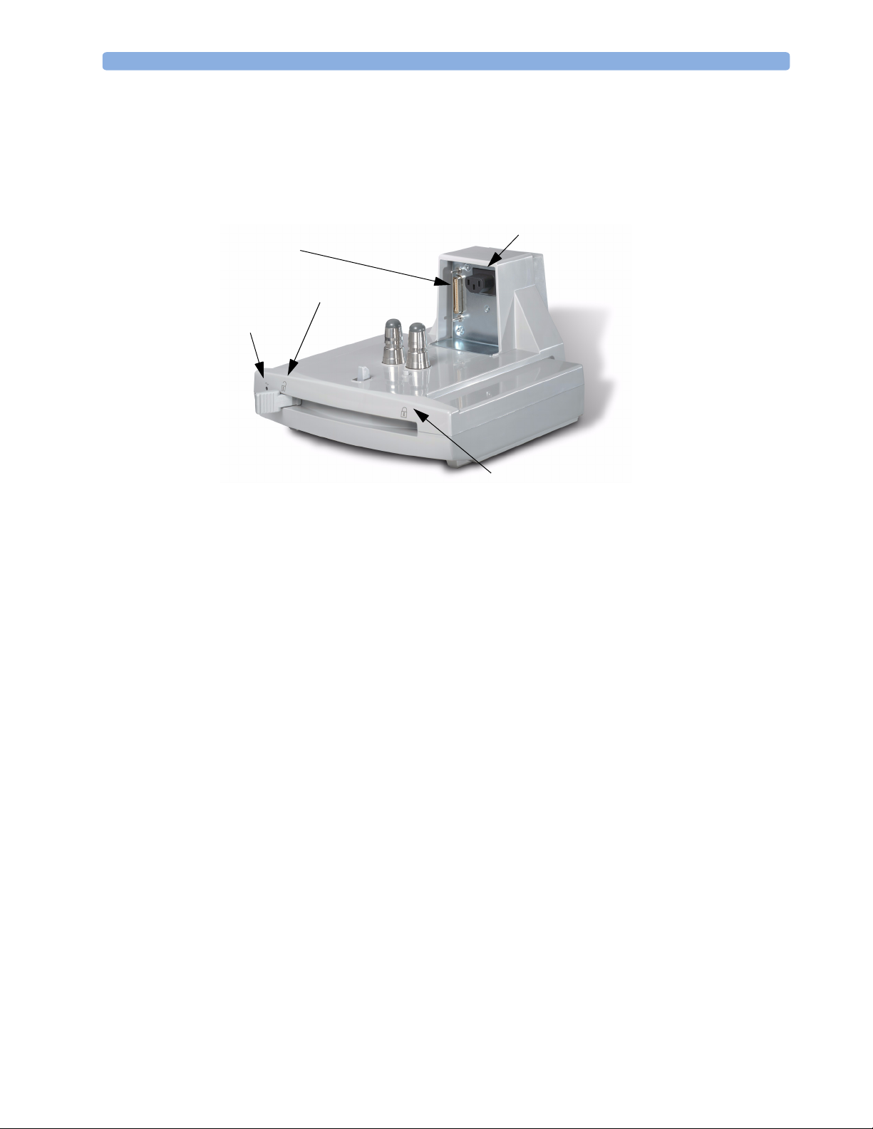
Docking Station
MP20/30/
40/50 only
The docking station provides quick mounting and connections in a one-step operation. By placing the
monitor on the docking station and closing the lever you can make the connection to power and to a
wired network, if present.
Data Connector
Open Position
Power On LED
Related Products
Power Connector
Locked Position
Related products extend the measurement capabilities of your monitor. None of the related devices
have their own power on/standby switches. They take their power from the monitor, and switch on
automatically when you turn on the monitor. A green power-on LED indicates when they are drawing
power from the monitor. A permanently illuminated, or flashing, red LED indicates a problem with
the unit that requires the attention of qualified service personnel.
Flexible Module Server (M8048A)
MP60/70/80
/90 only
The flexible module server (FMS) lets you use up to eight plug-in physiological measurement modules.
With the MP60/70/80 you can connect only one FMS. With the MP90 (M8010A) you can connect
two FMSs to use up to 10 measurement modules. For individual modules, the maximum that can be
used simultaneously in an FMS is: five pressure modules, four temperature modules, four VueLink
modules.
Connect the FMS to the monitor via the measurement server link cable (MSL). Use the MSL
connector on the left-hand side to connect additional measurement servers. Use the connector on the
right to connect to the monitor.
7
1 Basic Operation Related Products
1
1
2
3
Multi-Measurement
Server
2
Measurement server
mount
3
Flexible Module Server
4 Power on LED
5
Interruption indicator
5
4
Measurement Modules
You can use up to eight measurement modules with the Flexible Module Server (M8048A), two
additional modules in the integrated module slots in the MP60/MP70, and up to four in the integrated
slots in the MP40/MP50. Available modules are:
• Invasive blood pressure (M1006B)
• Temperature (M1029A)
• Oxygen saturation of arterial blood (SpO
) (M1020B)
2
• Cardiac output (M1012A), and Continuous cardiac output with M1012A Option #C10
• Transcutaneous gas (M1018A)
• Mixed venous oxygen saturation - SvO
(M1021A) MP60/70/80/90 monitor only
2
• Recorder (M1116B)
• VueLink device interface (M1032A)
• EEG (M1027A)
• Bispectral Index - BIS (M1034A)
You can plug and unplug modules during monitoring. Insert the module until the lever on the module
clicks into place. Remove a module by pressing the lever upwards and pulling the module out.
Reconnecting a module to the same monitor restores its label and measurement settings, such as alarms
limits. If you connect it to a different monitor, the module remembers only its label.
The connector socket on the front of each module is the same color as the corresponding connector
plug on the transducer or patient cable.
Press the Setup key on the module’s front to display the measurement’s setup menu on the monitor
screen. When the setup menu is open, a light appears above the key. Some modules have a second key.
On the pressure module, for example, it initiates a zeroing procedure.
8
Related Products 1 Basic Operation
Example Module (Pressure)
1Module name
2Setup key LED
3 Setup key to enter setup menu of
measurement modules or VueLink
device data window
4 Connector socket for patient cable/
transducer
5 Second module-specific key, for
example Zero
Multi-Measurement Server (M3001A)
The Multi-Measurement Server (MMS) can simultaneously monitor 3-, 5- or 10-lead ECG (including
arrhythmia and ST monitoring), respiration, SpO
Depending on the monitor model, you can connect it to the monitor via a cable or mount it either on
the left side of the FMS or on the back of the monitor, as shown here.
PRESS
1
2
3
80x80
Press
5
4
, NBP and either invasive pressure or temperature.
2
MMS mounted on rear of MP40/MP50
(left) and MP60/MP70
9

1 Basic Operation Related Products
M3001A Connectors and Symbols
1 White ECG/Resp connector
2 Blue SpO
5
3 Red NBP connector
4 & 5Combined pressure (red) and temperature
(brown) connector - connect either invasive
4
3
pressure transducer or temperature probe.
You might have a version of the MMS that
does not have this connector.
connector
2
2
1
6
NBP Start/Stop key -
6
7
starts or stops NBP
measurements
7
NBP STAT key - starts NBP
STAT series of
measurements
9
8
8
9
Measurement Server Extensions
The measurement server extensions connect to the MMS and use the MMS settings and power. Trend
data and measurement settings from the measurements in the extensions are stored in the measurement
server.
The measurement server extensions are not intended to be disconnected from the MMS. To exchange
an extension, you should exchange the measurement server and extension together.
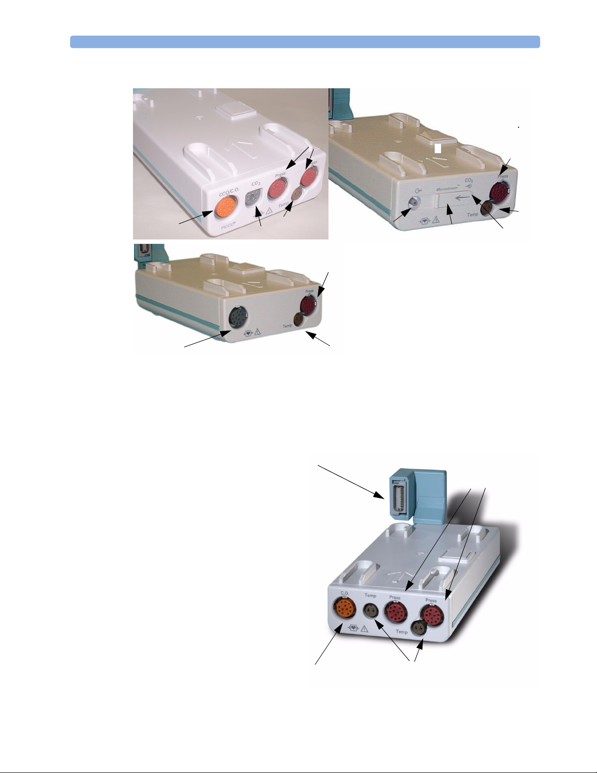
M3014A, M3015A and M3016A Capnography Extensions
The M3014A Capnography Extension adds mainstream capnography, and optionally one pressure
plus either a pressure or a temperature, Cardiac Output and Continuous Cardiac Output to the MMS.
The optional M3015A Microstream CO
either pressure or temperature to the MMS. The optional M3016A Mainstream CO
mainstream capnography and optionally either pressure or temperature to the MMS.
Extension adds microstream capnography and optionally
2
OR
Zero key - initiates a zero procedure for the
connected pressure transducer when
pressed and held for a second
Silence: acknowledges all active
alarms by switching off audible
alarm indicators and lamps
MSL cable connector to the monitor
Extension adds
2
10
Related Products 1 Basic Operation
M3014A Capnography
4
M3016A Mainstream
3
Pressure connectors (red)
1
Temperature connector (brown)
2
Mainstream connector CO2 (optional)
3
Cardiac Output connector
4
M3015A Microstream
1
1
2
2
3
7
6
5
1
2
Inlet
5
Microstream
6
Gas sample outlet
7
connector CO
2
M3012A Hemodynamic Measurement Server Extension
Connection to MMS
The M3012A Hemodynamic
Measurement Server Extension
(HMSE) can be connected to the
M3001A Multi-Measurement Server to
provide the following additional
measurements: Temperature, Pressure,
an additional Pressure or Temperature,
and C.O. and CCO measurements.
Cardiac Output (orange;
optional)
Pressure connectors
(red)
Temperature connectors (brown)
11
1 Basic Operation Operating and Navigating
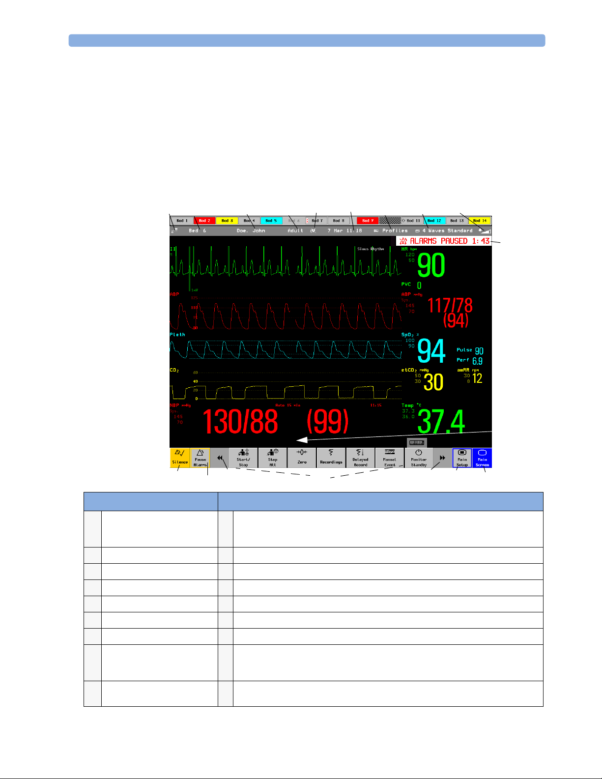
Operating and Navigating
Everything you need to operate the monitor is contained on its screen. Almost every element on the
screen is interactive. Screen elements include measurement numerics, waveforms, screen keys,
information fields, alarms fields and menus.
The configurability of the monitor means that often you can access the same element in different ways.
For example, you might be able to access an item through its on-screen setup menu, via a hard key, or
via a SmartKey. These Instructions for Use always describe how to access items via an on-screen menu.
You may use whichever way you find most convenient.
2
1
ABP Zero done at 11 Nov 02 7:31 am
18 16
17
3
5
4
67 8
9
10
11
15
14
13
12
Monitor information line Other screen elements
12
network connection indicator
1
(documented in Information
Center Instructions for Use)
bed label
2
patient identification
3
patient category
4
paced status
5
date and time
6
access the profiles menu
7
current screen name/enter
8
change screen menu
adjust alarm volume/level
9
indicator
alarm status area - shows active alarm messages
10
status line - shows information messages and prompting you for action
11
close all open menus and windows and return to main screen
12
enter Main Setup menu
13
scroll right to display more SmartKeys
14
SmartKeys - these change according to your monitor’s configuration
15
scroll left to display more SmartKeys
16
Pause Alarms - pauses alarm indicators. Pause duration depends on monitor
17
configuration. If pause duration is infinite, this key is labeled Alarms Off. Select again to
immediately re-enable alarm indicators.
Silence - acknowledges all active alarms by switching off audible alarm indicators and
18
lamps permanently or temporarily, if alarm reminder (ReAlarm) is configured on.
Loading...