


PN28480K-SG
Panasonic PN28480K-SG, PN28160K, PN28240K, PN28240K-ID, PN28480K Operation Manual
...
Thank you for purchasing our product.
This manual provides important information about safe and proper
operations of this Switching Hub.
Please read the "Important Safety Warnings" on pages 3 to 4.
Any problems or damage resulting from disassembly of this Switching Hub
by customers are note covered by the warranty.
Applicable product names and model numbers are described on page 2.
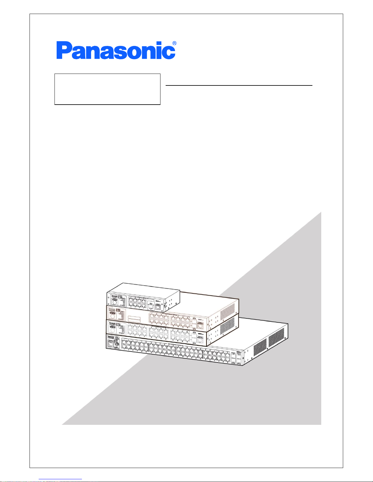
Layer 2 Switching Hub
Model Number: PN28080K/PN28160K
PN28240K/PN28480K
Operation Manual
for CLI

2
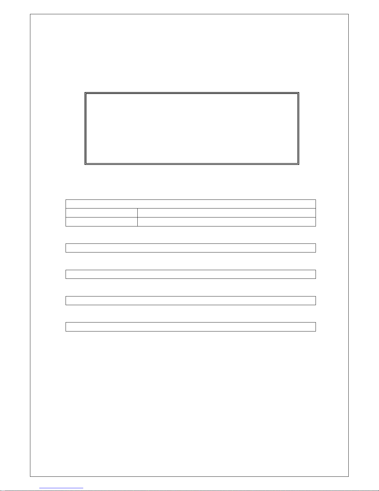
This operation manual is applicable to the following Switching Hubs:
Product name
Model No.
Firmware version
Switch-M48eG
PN28480K-ID
PN28480K-TH
PN28480K-MY
PN28480K-SG
2.0.1.05 or higher
Switch-M24eG
PN28240K-ID
PN28240K-TH
PN28240K-MY
PN28240K-SG
2.0.1.05 or higher
Switch-M16eG
PN28160K-ID
PN28160K-TH
PN28160K-MY
PN28160K-SG
2.0.1.05 or higher
Switch-M8eG
PN28080K-ID
PN28080K-TH
PN28080K-MY
PN28080K-SG
2.0.1.05 or higher

3
Important Safety Instructions
This chapter contains important safety instructions for preventing bodily
injury and/or property damage. You are required to follow them.
Severity of bodily injury and/or property damage, which could result from
incorrect use of the Switching Hub, are explained below.
The following symbols are used to classify and describe the type of
instructions to be observed.
This symbol is used to alert
users to what they must not do.
Do not use power supply other than AC 100 - 240V.
Deviation could lead to fire, electric shock, and/or equipment failure.
Do not handle the power cord with wet hand.
Deviation could lead to electric shock and/or equipment failure.
Do not handle this Switching Hub and connection cables during a
thunderstorm.
Deviation could lead to electric shock.
Do not disassemble and/or modify this Switching Hub.
Deviation could lead to fire, electric shock, and/or equipment failure.
Do not damage the power cord. Do not bend too tightly, stretch,
twist, bundle with other cord, pinch, put under a heavy object, and/or
heat it.
Damaged power cord could lead to fire, short, and/or electric shock.
Do not put foreign objects (such as metal and combustible) into the
opening (such as twisted pair port, console port, SFP extension slot),
and/or do not drop them into the inside of the Switching Hub.
Deviation could lead to fire, electric shock, and/or equipment failure.
This symbol indicates safety instructions.
Deviation from these instructions could lead
to bodily injury and/or property damage.
This symbol is used to alert
users to what they must do.
WARNING
This symbol indicates a potential hazard that
could result in serious injury or death.
CAUTION
WARNING

4
DO
Do not connect equipment other than
10BASE-T/100BASE-TX/1000BASE-T to twisted pair port.
Deviation could lead to fire, electric shock, and/or equipment failure.
Do not place this Switching Hub in harsh environment (such as near
water, high humid, and/or high dust).
Deviation could lead to fire, electric shock, and/or equipment failure.
Do not place this Switching Hub under direct sun light and/or high
temperature.
Deviation could lead to high internal temperature and fire.
Do not install this Switching Hub at the location with continuous
vibration or strong shock, or at the unstable location.
Deviation could lead to injury and/or equipment failure.
Do not install any module other than the separately sold SFP module
(PN54021K/PN54023K) to SFP extension slot.
Deviation could lead to fire, electric shock, and/or equipment failure.
Do not put this Switching Hub into fire.
Deviation could lead to explosion and/or fire.
Do not use the supplied power cord for anything other than this
product.
Deviation could lead to fire, electric shock, and/or equipment failure.
Do not place this Switching Hub under direct sun light and or high
temperature.
Deviation could lead to fire to high internal temperature and fire.
WARNING

5
Use the bundled power cord (AC 100 – 240V specifications).
Deviation could lead to electric shock, malfunction, and/or
equipment failure.
Unplug the power cord in case of equipment failure.
Deviation, such as keeping connected for a long time, could lead to
fire.
Connect this Switching Hub to ground.
Deviation could lead to electric shock, malfunction, and/or
equipment failure.
Connect the power cord firmly to the power port.
Deviation could lead to electric fire, shock, and/or malfunction.
Unplug the power cord if the STATUS/ECO LED (Status/ECO mode)
blinks in orange (system fault).
Deviation, such as keeping connected for a long time, could lead to
fire.
When this Switching Hub is installed on wall surface, mount it firmly so
as not to drop down because of weight of the main body and
connection cable.
Deviation, could lead to injury and/or equipment failure.
Handle the Switching Hub carefully so that fingers or hands may not
be damaged by twisted pair port, SFP extension slot, console port, or
power cord hook block.
WARNING
CAUTION

6
Basic Instructions for the Use of This
Product
For inspection and/or repair, consult the shop.
Use commercial power supply from a wall socket, which is close and easily
accessible to this Switching Hub.
Unplug the power cord when installing or moving this Switching Hub.
Unplug the power cord when cleaning this Switching Hub.
Use this Switching Hub within the specifications. Deviation could lead to
malfunction.
When connecting a cable, hold the Switching Hub firmly.
Do not put a floppy disk or a magnetic card near the rubber feet (with built-in
magnets). Otherwise, recorded content may be lost.
After installing this Switching Hub on an OA desk, do not move either without
dismounting it. Otherwise, the desk surface may be damaged.
Do not touch the metal terminal of the RJ45 connector, the modular plug of
connected twisted pair cable, or the metal terminal of the SFP extension slot.
Do not place charged objects in the proximity of them. Static electricity could
lead to equipment failure.
Do not put the modular plug of the connected twisted pair cable on objects
that can carry static charge, such as carpet. Do not place it in the proximity.
Static electricity could lead to equipment failure.
Do not put a strong shock, including dropping, to this Switching Hub.
Deviation could lead to equipment failure.
Before connecting a console cable to the console port, discharge static
electricity, for example by touching metal appliance (do not discharge by
touching this Switching Hub).
Do not store and/or use this Switching Hub in the environment with the
characteristics listed below.
(Store and/or use this Switching Hub in the environment in accordance with
the specification.)
- High humidity. Possible spilled liquid (water).
- Dusty. Possible static charge (such as carpet).
- Under direct sunlight.
- Possible condensation. High/low temperature exceeding the specifications
environment.
- Strong vibration and/or strong shock.
Please use this Switching Hub in place where ambient temperature is from 0
to 50C.

7
Failure to meet the above conditions may result in fire, electric shock,
breakdown, and/or malfunction. Please take notice because such cases are
out of guarantee.
Additionally, do not cover the bent hole of this Switching Hub.
Deviation could lead to high internal temperature, equipment failure and/or
malfunction.
When stacking Switching Hubs, leave a minimum of 20 mm space between
them.
Operation is not guaranteed if a module other than the optional SFP
extension modules (PN54021K/PN54023K) is inserted into the SFP extension
slot. For the latest information about compatible SFP extension modules,
check our website.
1. Panasonic will not be liable for any damage resulting from the operation
not in accordance with this document or the loss of communications,
which may or may not be caused by failure and/or malfunction of this
product.
2. The contents described in this document may be changed without prior
notice.
3. For any question, please contact the shop where you purchased the
product.
* Brands and product names in this document are trademarks or registered
trademarks of their respective holders.

8
Table of Contents
Important Safety Instructions ................................................................................ 3
Basic Instructions for the Use of This Product ....................................................... 6
1. Command Hierarchy ...................................................................................... 10
2. Basic Information Display .............................................................................. 14
3. Basic Switch Configuration ............................................................................ 23
3.1. System Administration Configuration ..................................................... 23
3.1.1. Username and Password Configuration ............................................ 31
3.2. IP Address Configuration ......................................................................... 34
3.3. SNMP Configuration ................................................................................ 43
3.4. Port Configuration ................................................................................... 77
3.5. System Security Configuration ................................................................ 95
3.5.1. Console Configuration ..................................................................... 100
3.5.2. Telnet Configuration ........................................................................ 105
3.5.3. SSH Configuration ............................................................................ 114
3.5.4. Web Configuration .......................................................................... 122
3.5.5. RADIUS Server Configuration .......................................................... 127
3.5.6. Configuration of the Easy IP Address Setup Function .................... 137
3.5.7. Configuration of the Syslog Transmission Function ........................ 142
3.6. MAC Address Table Display, Registration, and Configuration ............. 147
3.7. Time Configuration ................................................................................ 159
3.8. ARP Configuration ................................................................................. 170
4. Advanced Switch Configuration ................................................................. 176
4.1. VLAN Configuration .............................................................................. 176
4.1.1. Internet Mansion Function Configuration ...................................... 189
4.2. Link Aggregation Configuration ........................................................... 195
4.2.1. About Link Aggregation .................................................................. 195
4.3. Port Monitoring Configuration ............................................................. 201
4.4. Access Control Configuration ................................................................ 206
4.5. QoS (Quality of Service) Configuration ................................................. 230
4.6. Bandwidth Control Configuration ......................................................... 237
4.7. Storm Control Configuration ................................................................. 242
4.8. Authentication Function Configuration ................................................ 250
4.9. AAA Configuration ................................................................................ 263
4.10. Authentication Log Configuration ...................................................... 273
4.11. IEEE802.1X Port-Based Authentication Configuration ....................... 279
4.12. IEEE802.1X MAC-Based Authentication Configuration ...................... 298
4.13. MAC Authentication Configuration .................................................... 319
4.14. WEB Authentication Configuration .................................................... 333
4.8. LED Base Mode Configuration .............................................................. 359
4.9. Line Configuration ................................................................................. 364
4.9.1. Loop Detection Configuration ......................................................... 364
4.9.2. Configuration of MNO Series Power Saving Mode ......................... 371
4.9.3. Line Configuration Display ............................................................... 374
4.10. Port Group Configuration ............................................................ 377
9
5. Statistical Information Display .................................................................... 384
.......................................................................... 390 6. Configuration File Transfer
....................................................................................... 393 7. Firmware Upgrade
......................................................................................................... 396 8. Reboot
8.1. Normal Reboot ....................................................................................... 396
8.2. Restoration to Factory Default Settings ................................................ 399
8.3. Reboot Timer Configuration .................................................................. 402
9. Ping Execution ............................................................................................. 405
.................................................................................... 408 10. System Log Display
....................................... 419 11. Save and Display of Configuration Information
................................................ 424 12. Obtaining Technical Support Information
Appendix A. Specifications ................................................................................. 427
Appendix B. Easy IP Address Setup Function ................................................... 428
Appendix C. Example of Network Configuration using Loop Detection Function
and Its Precautions ....................................................................... 429
Appendix D. MIB List .......................................................................................... 431
Troubleshooting ................................................................................................. 436
After-sales Service ............................................................................................... 437

10
1. Command Hierarchy
There are four levels in the hierarchy.
(1) User mode:
This is the default mode after login. Limited operations are allowed.
(2) Privileged mode:
This mode allows you to check the state of the Switching Hub, to edit
configuration files, etc.
(3) Global configuration mode:
This mode allows you to set the general configuration of the Switching
Hub.
(4) Interface configuration mode:
This mode allows you to set individual items, such as each port and each
VLAN, in details.
Fig. 1-1 Command hierarchy
enable Command
• Enter this command to switch from the User mode to the Privileged mode.
M24eG> ···················· User mode
M24eG> enable ·············· User mode Privileged mode
M24eG# ···················· Privileged mode
M24eG# disable ·············· Privileged mode User mode
M24eG> ···················· User mode
disable Command
• Enter this command to switch from the Privileged mode to the User mode.
M24eG# ···················· Privileged mode
M24eG# disable ·············· Privileged mode User mode
M24eG> ···················· User mode
M24eG> enable
M24eG# configure
M24eG(config)# interface gi0/1
M24eG(config-if)# exit
M24eG(config)# exit
M24eG#

11
configure Command
• Enter this command to switch from the Privileged mode to the Global
configuration mode.
M24eG# ····················· Privileged mode
M24eG# configure ············ Privileged mode
Global configuration mode
M24eG(config)# ·············· Global configuration mode
interface Command
• Enter this command to switch from the Global configuration mode to the
Interface configuration mode.
M24eG(config)# ·············· Global configuration mode
M24eG(config)# interface vlan1 ·· Global configuration mode
Interface
configuration mode (vlan1)
M24eG(config-if)# exit ········· Interface configuration mode
Global configuration mode
M24eG(config)# interface Gigabitethernet0/1
········· Global configuration mode
Interface
configuration mode (interface1)
M24eG(config-if)# exit ········· Interface configuration mode
Global configuration mode
M24eG(config)# ·············· Global configuration mode
exit Command
• Enter this command to return to the previous mode.
M24eG(config-if)# exit ········· Interface configuration mode
Global configuration mode
M24eG(config)# exit ··········· Global configuration mode
Privileged mode
M24eG# exit ·················· Privileged mode User mode
M24eG> ····················· User mode

12
end Command
• Enter this command to switch from configuration modes to the Privileged
mode.
M24eG(config-if)# end ········ Interface configuration mode
Privileged mode
M24eG# configure
M24eG(config)# end ·········· Global configuration mode
Privileged mode
logout Command
• Enter this command to return to the menu screen from any command
mode.
M24eG(config)# logout ······· Configuration mode Menu
? Command
• Enter a question mark (?) to view available commands in that command
mode.
Fig. 1-2 ? command
Command History Support
• Press the (up arrow) key to view the history of the entered commands.
M24eG> ?
enable Privilege level to go to.
exit Exit from current mode
logout To logout from the CLI shell
ping Send ICMP ECHO_REQUEST to network hosts
M24eG>

13
Command-line Completion Support
• Enter a question mark (?) immediately after a command. This will
show command candidates to complete the entered command.
Fig. 1-3 Command-line completion support
Abbreviated Command Entry
After entering just enough characters of a command or an argument to
identify it uniquely, you can omit the rest of the command or the argument.
[Example of Abbreviated Command Entry]
enable en
show running-config sh ru
[Bad Example of Abbreviated Command Entry]
co Because both "configure" and "copy" are possible, an error occurs.
Symbols used in the command description are as follows:
< > : Required - You must enter this.
{ | } : Selections - Select one from the selections.
[ ] : Option - Enter as required.
Commands are case sensitive. Uppercase and lower case letters are treated as
different letters.
Note that in this manual, ports are specified for Switch-M24eG (24 ports)
except for a few commands. When entering a command, make sure to specify
existing port numbers of your switch.
M24eG# configure
M24eG(config)# ip address ?
<ip-address> ex: 192.168.1.1
M24eG(config)# ip address
14
2. Basic Information Display
Enter the commands listed below in the "Privileged mode" to show this
Switching Hub's basic information.
Command to show the system information (up time and version information)
M24eG#
show sys-info
Command to show the address information (MAC address and IP address
information)
M24eG#
show ip conf
Command to show the ipv6 address information (MAC address and IPv6
address information)
M24eG#
show ipv6 conf

15
<Command Entry Example>
An example of executing the command to show the system
information is shown below.
Fig. 2-1 Example of executing the command to show the system information
(1) System up for
Shows the Switching Hub's up duration in days and time.
(2) Boot Code Version
Shows the Switching Hub's boot code version.
(3) Runtime Code Version
Shows the Switching Hub's firmware version.
(4) Hardware Information
Shows the Switching Hub's hardware information.
M24eG> enable
M24eG# show sys-info
System up for : 0 days, 0:1:29
Boot Code Version : 1.00.17
Runtime Code Version : 1.0.0.07
Hardware Information
Version : A1
DRAM Size : 128MB
Fixed Baud Rate : 9600bps
FLASH Size : 32MB
Administration Information
Switch Name :
Switch Location :
Switch Contact :
System Address Information
MAC Address : 00:C0:8F:A0:13:98
IP Address : 0.0.0.0
Subnet Mask : 0.0.0.0
Default Gateway : 0.0.0.0
System Address Information
IPv6 Status : Disable
MAC Address : 00:C0:8F:A0:13:98
IPv6 Address/prefixlen : ::/128
IPv6 Link Local Address : ::
IPv6 Default Gateway : ::
M24eG#
(1)
(2)
(3)
(4)
(9)
(14)
(4)
(6)
(7)
(4)
(5)
(8)
(4)
(5)
(13)
(10)
(11)
(12)
(15)
(16)
(17)
(18)
(19)
(20)
(21)
16
(5) Version
Shows the Switching Hub's hardware version.
(6) DRAM Size
Shows the Switching Hub's DRAM memory size.
(7) Fixed Baud Rate
Shows the baud rate of the Switching Hub's console port.
(8) Flash Size
Shows the Switching Hub's flash memory size.
(9) Administration Information
Shows the Switching Hub's administration information.
(10) Switch Name
Shows the Switching Hub's current host name.
(11) Switch Location
Shows the Switching Hub's current installation location name.
(12) Switch Contact
Shows the Switching Hub's current contact information.
(13) System Address Information
Shows the Switching Hub's address information.
(14) MAC Address
Shows the Switching Hub's MAC address.
(15) IP Address
Shows the Switching Hub's current IP address in operation.
(16) Subnet Mask
Shows the Switching Hub's current subnet mask in operation.
(17) Default Gateway
Shows the Switching Hub's current default gateway in operation.

17
(18) IPv6 Status
Shows the IPv6 Status (Enabled or Disabled).
Enabled
The IPv6 function is enabled.
Disabled
The IPv6 function is disabled.
(19) IPv6 Address/prefixlen
Shows the Switching Hub's current ipv6 address and prefix length in
operation.
(20) IPv6 Link Local Address
Shows the Switching Hub's current ipv6 link local address in operation.
(21) IPv6 Default Gateway
Shows the Switching Hub's current ipv6 default gateway in operation.
18
<Command Entry Example>
An example of executing the command to show the address
information is shown below.
Fig. 2-2 Example of executing the command to show the address information
(1) MAC Address
Shows the Switching Hub's MAC address.
(2) IP Address
Shows the Switching Hub's current IP address in operation.
(3) Subnet Mask
Shows the Switching Hub's current subnet mask in operation.
(4) Default Gateway
Shows the Switching Hub's current default gateway in operation.
M24eG> enable
M24eG# show ip conf
MAC Address : 00:C0:8F:A0:13:98
IP Address : 0.0.0.0
Subnet Mask : 0.0.0.0
Default Gateway : 0.0.0.0
M24eG#
(1)
(2)
(3)
(4)
19
<Command Entry Example>
An example of executing the command to show the ipv6 address
information is shown below.
Fig. 2-3 Example of executing the command to show the ipv6 address
information
(1) IPv6 Status
Shows the IPv6 Status (Enabled or Disabled).
Enabled
The IPv6 function is enabled.
Disabled
The IPv6 function is disabled.
(2) MAC Address
Shows the Switching Hub's MAC address.
(3) IPv6 Address/prefixlen
Shows the Switching Hub's current IPv6 address in operation.
(4) IPv6 Link Local Address
Shows the Switching Hub's current ipv6 link local address in operation.
(5) IPv6 Default Gateway
Shows the Switching Hub's current IPv6 default gateway in operation.
M24eG> enable
M24eG# show ipv6 conf
IPv6 Status : Disable
MAC Address : 00:C0:8F:A0:13:98
IPv6 Address/prefixlen : ::/128
IPv6 Link Local Address : ::
IPv6 Default Gateway : ::
M24eG#
(1)
(2)
(3)
(4)
(5)

20
show sys-info
Shows the Switching Hub's system information (such as up time and
version information).
[Parameter]
Parameter name
Description
None
None
[Factory Default Setting]
Parameter name
Factory default setting
None
None
[Setting Range]
Parameter name
Setting range
None
None
[Note]
Parameter name
Note
None
None
21
show ip conf
Shows the address information (such as MAC address and IP address) of
the Switching Hub.
[Parameter]
Parameter name
Description
None
None
[Factory Default Setting]
Parameter name
Factory default setting
None
None
[Setting Range]
Parameter name
Setting range
None
None
[Note]
Parameter name
Note
None
None

22
show ipv6 conf
Shows the ipv6 address information (such as MAC address and IPv6
address) of the Switching Hub.
[Parameter]
Parameter name
Description
None
None
[Factory Default Setting]
Parameter name
Factory default setting
None
None
[Setting Range]
Parameter name
Setting range
None
None
[Note]
Parameter name
Note
None
None
23
3. Basic Switch Configuration
3.1. System Administration Configuration
Configure the host name, installation location and contact information in
"Global configuration mode." Confirm the configuration information by
executing the "show sys-info" command in "Privileged mode."
Command to show the system information
M24eG#
show sys-info
Command to set the host name
M24eG(config)#
hostname <hostname>
Command to delete the host name
M24eG(config)#
no hostname
Command to set the installation location
M24eG(config)#
snmp-server location <server location>
Command to delete the installation location
M24eG(config)#
no snmp-server location
Command to set the contact information
M24eG(config)#
snmp-server contact <server contact>
Command to delete the contact information
M24eG(config)#
no snmp-server contact
24
<Command Entry Example>
An example of executing the command to show the system
information is shown below.
Fig. 3-1-1 Example of executing the command to show the system information
Terms related to this section are explained below.
(1) Administration Information
Shows the Switching Hub's administration information.
(2) Switch Name
Shows the Switching Hub's current host name.
(3) Switch Location
Shows the Switching Hub's current installation location name.
M24eG> enable
M24eG# show sys-info
System up for : 0 days, 0:1:29
Boot Code Version : 1.00.17
Runtime Code Version : 1.0.0.07
Hardware Information
Version : A1
DRAM Size : 128MB
Fixed Baud Rate : 9600bps
FLASH Size : 32MB
Administration Information
Switch Name :
Switch Location :
Switch Contact :
System Address Information
MAC Address : 00:C0:8F:A0:13:98
IP Address : 0.0.0.0
Subnet Mask : 0.0.0.0
Default Gateway : 0.0.0.0
System Address Information
IPv6 Status : Disable
MAC Address : 00:C0:8F:A0:13:98
IPv6 Address/prefixlen : ::/128
IPv6 Link Local Address : ::
IPv6 Default Gateway : ::
M24eG#
(1)
(5)
(2)
(3)
(4)

25
(4) Switch Contact
Shows the Switching Hub's current contact information.

26
show sys-info
Shows the system information.
[Parameter]
Parameter name
Description
None
None
[Factory Default Setting]
Parameter name
Factory default setting
None
None
[Setting Range]
Parameter name
Setting range
None
None
[Note]
Parameter name
Note
None
None
27
hostname <hostname>
Sets or edits the system name.
no hostname
Deletes the system name.
[Parameter]
Parameter name
Description
<hostname>
Set the system name.
[Factory Default Setting]
Parameter name
Factory default setting
<hostname>
None
[Setting Range]
Parameter name
Setting range
<hostname>
Up to 50 one-byte characters
Allowed characters: alphanumeric character
(A-Z, a-z, 0-9)
symbol (!@#$&_-.)
white space
[Note]
Parameter name
Note
<hostname>
To set a system name containing white spaces,
enclose the entire name with a pair of
double-quotation marks (" ").
Example: hostname "switch a"

28
snmp-server location <server location>
Sets or edits the installation location information.
no snmp-server location
Deletes the installation location information.
[Parameter]
Parameter name
Description
<server location>
Set the installation location.
[Factory Default Setting]
Parameter name
Factory default setting
<server location>
None
[Setting Range]
Parameter name
Setting range
<server location>
Up to 50 one-byte characters
Allowed characters: alphanumeric character (A-Z,
a-z, 0-9)
symbol (!@#$&_-.)
white space
[Note]
Parameter name
Note
<server location>
To set a location name containing white spaces,
enclose it with a pair of double-quotation marks
(" ").
Example: snmp-server location "Office 2F"

29
snmp-server contact <server contact>
Sets or edits the contact information.
no snmp-server contact
Deletes the contact information.
[Parameter]
Parameter name
Description
<server contact>
Set the contact information.
[Factory Default Setting]
Parameter name
Factory default setting
<server contact>
None
[Setting Range]
Parameter name
Setting range
<server contact>
Up to 50 one-byte characters
Allowed characters: alphanumeric character (A-Z,
a-z, 0-9)
symbol (!@#$&_-.)
white space
[Note]
Parameter name
Note
<server contact>
To set contact information containing white
spaces, enclose it with a pair of double-quotation
marks (" ").
Example: snmp-server contact "network
manager"

30
<Configuration Example>
Overview: Set this Switching Hub's administration information (host
name, installation location, and contact information).
(1) Set this Switching Hub's name to "Switch."
(2) Set this Switching Hub's installation location to "Office-2F."
(3) Set this Switching Hub's contact information to "manager."
Fig. 3-1-2 Example of configuring the Switching Hub's administration
information
M24eG> enable
M24eG# configure
M24eG(config)# hostname Switch
Switch(config)# snmp-server location Office-2F
Switch(config)# snmp-server contact manager
Switch(config)# exit
Switch#
(1)
(2)
(3)
 Loading...