


PM4H-M
Panasonic PM4H-M, PM4H-SD, PM4H-W, PM4H-F, LT4H Specifications
...
’06–’07
LC2H
98
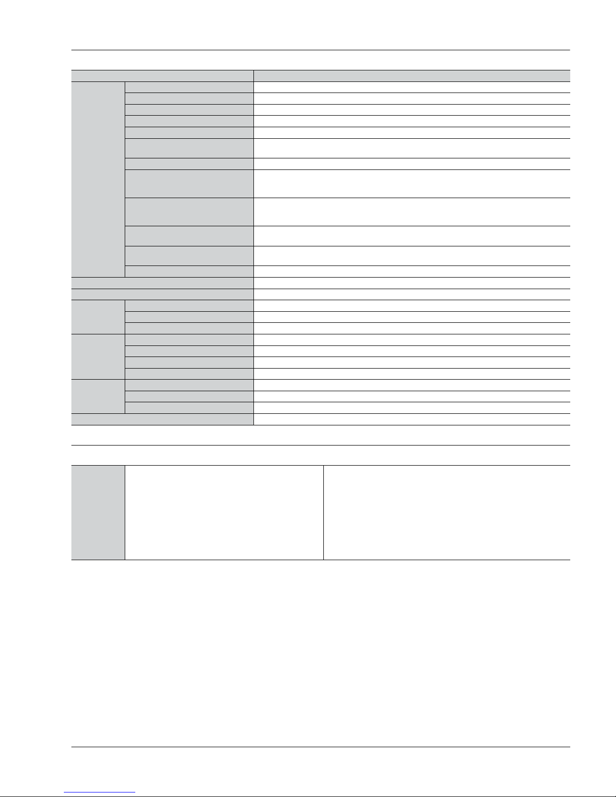
Product types
1. Panel mounting type
1) One-touch installation type
1 Standard type
Note) Please ask us about types without front resetting.
2 Backlight type
DIN HALF SIZE
LCD COUNTER
LC2H
Counters
No. digits Counting speed Front reset Input method Part No.
8 digits
2 kHz/30 Hz switchable
Yes
Non-voltage input type LC2H-FE-2KK
Voltage input type (4.5 to 30 V DC) LC2H-FE-DL-2KK
30 Hz Free voltage input type (24 to 240 V AC/DC) LC2H-FE-FV-30
No. digits Counting speed Front reset Input method Part No.
8 digits 2 kHz/30 Hz switchable Yes Voltage input type (4.5 to 30 V DC) LC2H-FE-DL-2KK-B
Panel mounting type
One-touch installation type
Panel mounting type
Installation frame type
PC board mounting type
Features
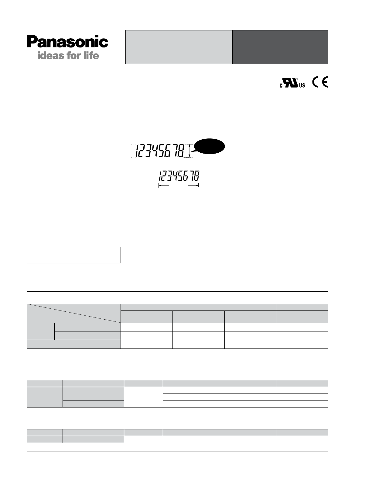
1. 8.7 mm .343 inch Character Height
(previously 7 mm)
Easy-to-read character height increased
from 7 mm to 8.7 mm .276 inch to .343
inch.
2. Plenty of Digits
3. Counting Speed Switchable
between 2 kHz and 30 Hz
4. Panel Mounting Type Features
2 Installation Methods
Comes with very easy one-touch
installation type and also installation
frame type that uses the bracket on the
timer/counter. Choose a method that
suits the application.
5. Battery Replacement Easy on
Environment
To replace battery simply remove body
for the one-touch installation type, and
remove battery lid for the installation
frame type.
6. Screw Terminals Designed for
Safety
Built in finger protection.
7. Panel Covers Replacable
(Standard color is ash gray.)
Change the panel design by replacing
with a black panel cover.
8. Conforms to IP66 Protective
Construction (Only installation frame
type.) (Front panel surface)
9. Input Methods
1) Non-voltage input method
2) Voltage input method
3) Free voltage input method
10. Backlight Type Added to Series
and Now 2-color Switchable (green/
red)
Easy viewing even in dark places and
switchable between green and red
(Voltage input type).
11. Compliant with UL, c-UL and CE.
RoHS Directive compatibility information
http://www.nais-e.com/
8.7mm
.343inch
8 digits
Product chart
Type
Installation type
Standard type Backlight type
Non-voltage input type
Voltage input type
(4.5 to 30 V DC)
Free voltage input type
(24 to 240 V AC/DC)
Voltage input type
(4.5 to 30 V DC)
Panel
mounting
type
One-touch installation type
Installation frame type
PC board mounting type ———
CTi Automation - Phone: 800.894.0412 - Fax: 208.368.0415 - Web: www.ctiautomation.net - Email: info@ctiautomation.net
LC2H
99
2) Installation frame type
1 Standard type
Note) Please ask us about types without front resetting.
2 Backlight type
2. PC board mounting type
Specifications
No. digits Counting speed Front reset Input method Part No.
8 digits
2 kHz/30 Hz switchable
Yes
Non-voltage input type LC2H-F-2KK
Voltage input type (4.5 to 30 V DC) LC2H-F-DL-2KK
30 Hz Free voltage input type (24 to 240 V AC/DC) LC2H-F-FV-30
No. digits Counting speed Front reset Input method Part No.
8 digits 2 kHz/30 Hz switchable Yes Voltage input type (4.5 to 30 V DC) LC2H-F-DL-2KK-B
No. digits Counting speed Front reset Input method Part No.
8 digits
2 kHz
No Non-voltage input type
LC2H-C-2K-N
30 Hz LC2H-C-30-N
1. Panel mounting type
Notes) 1. The value given for battery life is calculated based on continuous operation (count input signal ON/OFF = 1:1), therefore, this value is not guaranteed.
Also, battery life is decreased 30% when operation is continuous with 2 kHz count inputting in 2 kHz mode.
2. Operation is at 25 Hz when using 24 V AC.
3. Only for installation frame type.
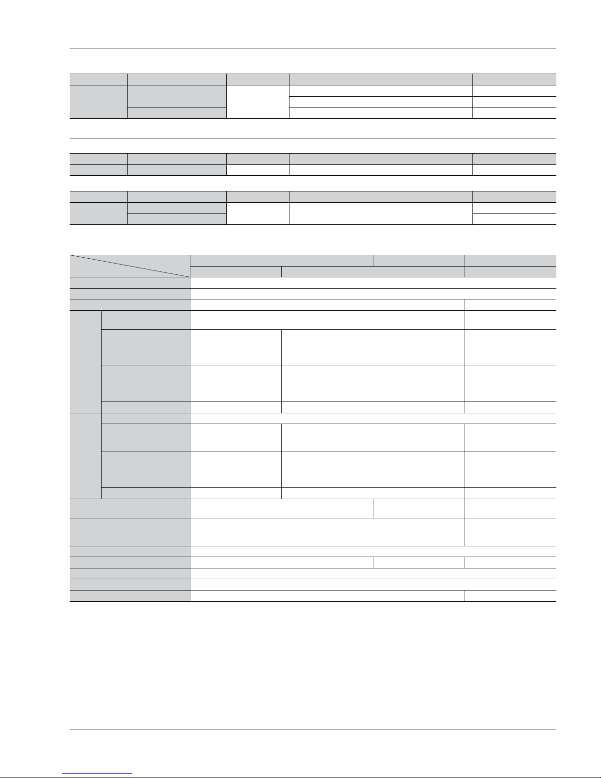
Type
Item
Standard type Backlight type Standard type
Non-voltage input Voltage input Free voltage type
No. digits 8 digits
External power supply Not required (built-in battery)
Max. counting speed 2 kHz/30 Hz (Switchable by switch) 30 Hz (Note 2)
Count
input
Min. input signal width
(ON: OFF = 1:1)
0.25 ms/16.7 ms (Switchable by switch) 16.7 ms
Input method (signal)
Non-voltage input using
contacts or open collector
connection
High level: 4.5 to 30 V DC
Low level: 0 to 2 V DC
High level:
24 to 240 V AC/DC
Low level:
0 to 2.4 V AC/DC
Input impedance
When shorted:
Max. 10 kΩ
When open:
Max. 750 kΩ
Approx. 4.7 kΩ —
Residual voltage Max. 0.5 V — —
Reset
input
Min. input signal width 200 ms
Input method (signal)
Non-voltage input using
contacts or open collector
connection
High level: 4.5 to 30 V DC
Low level: 0 to 2 V DC
Non-voltage input using
contacts or open collector
connection
Input impedance
When shorted:
Max. 10 kΩ
When open:
Max. 750 kΩ
Appox. 4.7 kΩ
When shorted:
Max. 10 kΩ
When open:
Max. 750 kΩ
Residual voltage Max 0.5 V — Max. 0.5 V
Display method 7-segment LCD
7-segment LCD
With green/red backlight
7-segment LCD
Breakdown voltage (initial) Between charged and uncharged parts: 1,000 V AC for 1 minute.
Between charged and
uncharged parts: 2,000 V
AC for 1 minute.
Insulation resistance (initial) Min. 100 MΩ (measured at 500 V DC) Measurement location same as for break down voltage.
Backlight power — 24 V DC (±10%) —
Protective construction (Note 3) IEC Standard IP66 (only panel front: when using rubber gasket)
Accessories (Note 3) Rubber gasket, mounting bracket
Battery life 7 years (at 25°C 77°F) Note 1 6 years (at 25°C 77°F)
CTi Automation - Phone: 800.894.0412 - Fax: 208.368.0415 - Web: www.ctiautomation.net - Email: info@ctiautomation.net
LC2H
100
Applicable standard
Safety standard EN61010-1 Pollution Degree 2/Overvoltage Category III
EMC
(EMI)EN61000-6-4
Radiation interference electric field strength
Noise terminal voltage
(EMS)EN61000-6-2
Static discharge immunity
RF electromagnetic field immunity
EFT/B immunity
Conductivity noise immunity
Power frequency magnetic field immunity
EN55011 Group1 ClassA
EN55011 Group1 ClassA
EN61000-4-2 4 kV contact
8 kV air
EN61000-4-3 10 V/m AM modulation (80 MHz to 1 GHz)
10 V/m pulse modulation (895 MHz to 905 MHz)
EN61000-4-4 2 kV (power supply line)
EN61000-4-6 10 V/m AM modulation (0.15 MHz to 80 MHz)
EN61000-4-8 30 A/m (50 Hz)
2. PC board mounting type
3. Common
Type
Item
PC board mounting type
Input method Non DC voltage input
No. digits 8 digits
Rated operation voltage 3 V DC
Allowable operation voltage range 2.7 to 3.3 V DC
Current consumption Max. 30 µA (max. 250 µA during reset input)
Max. counting speed 2 kHz 30 Hz
Count
input
Min. input signal width
(ON: OFF = 1:1)
0.25 ms 16.7 ms
Input method Non-voltage input using contacts or open collector connection
Input impedance
When shorted: Max. 10 kΩ
When open: Max. 750 kΩ
Residual voltage Max. 0.5 V
Reset
input
Min. input signal width 10 ms
Input method Non-voltage input using contacts or open collector connection
Input impedance
When shorted: Max. 10 kΩ
When open: Max. 750 kΩ
Residual power Max. 0.5 V
Break down voltage (initial) Between charged and uncharged parts: 1,000 V AC for 1 minute.
Insulation resistance (initial) Min. 100 MΩ (measured at 500 V DC) Measurement location same as for break down voltage.
Type
Item
Panel mounting/PC board mounting types
Vibration resistance
Functional 10 to 55 Hz (1 cycle/min.), single amplitude: 0.15 mm .006 inch (10 min. on 3 axes)
Destructive 10 to 55 Hz (1 cycle/min.), single amplitude: 0.375 mm .015 inch (1 hr. on 3 axes)
Shock resistance
Functional Min. 98 m/s2 (4 times on 3 axes)
Destructive Min. 294 m/s2 (5 times on 3 axes)
Operation temperature –10 to +55°C +14 to +131°F (without frost or dew)
Storage temperature –25 to +65°C –13 to +149°F (without frost or dew)
Ambient humidity 35 to 85% RH (non-condensing)
CTi Automation - Phone: 800.894.0412 - Fax: 208.368.0415 - Web: www.ctiautomation.net - Email: info@ctiautomation.net
LC2H
101
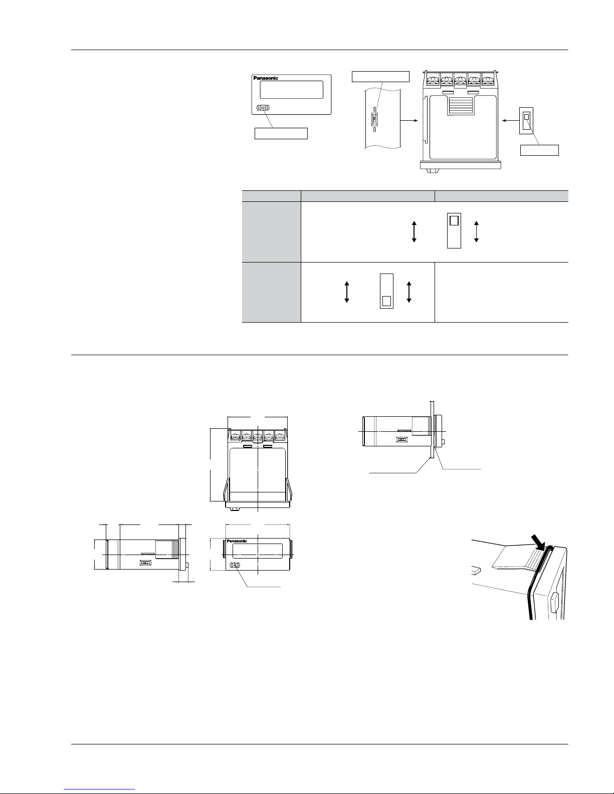
Part names
1. Front reset button
This button resets the count value. It
does not work when the lock switch is
ON. Be aware that battery life will
decrease if this switch is used frequently.
2. Lock switch (Refer to chart on
right.)
Disable the front reset button.
Note) Turn ON at the LCD side (reset disabled) and
OFF at the terminal block side (reset enabled).
3. Count speed switch (Refer to chart
on right.)
Use this switch to switch the count speed
between 30 Hz and 2 kHz. (On the nonvoltage and voltage input types, 30 Hz is
on the LCD side and 2 kHz is on the
terminal block side. Fixed at 30 Hz for
free voltage input type.)
Note) You must press the front reset button when you
change the count speed switch setting.
Confirm, however, that the Lock Switch is OFF
(front switches operable).
Notes) 1. ❇Default setting when shipped.
2. Make the switch setting before installing to panel.
Non-voltage input/voltage input Free voltage input
Lock switch
(Unit display 1)
Count speed
switch
(Unit display 2)
Count speed switch
Lock switch
RESET
COUNTER
LC2H
Front reset button
(Terminal block side)
(LCD side)
OFF❇
ON
(Terminal block side)
(LCD side)
2k Hz
30Hz❇
—
(Fixed at 30 Hz)
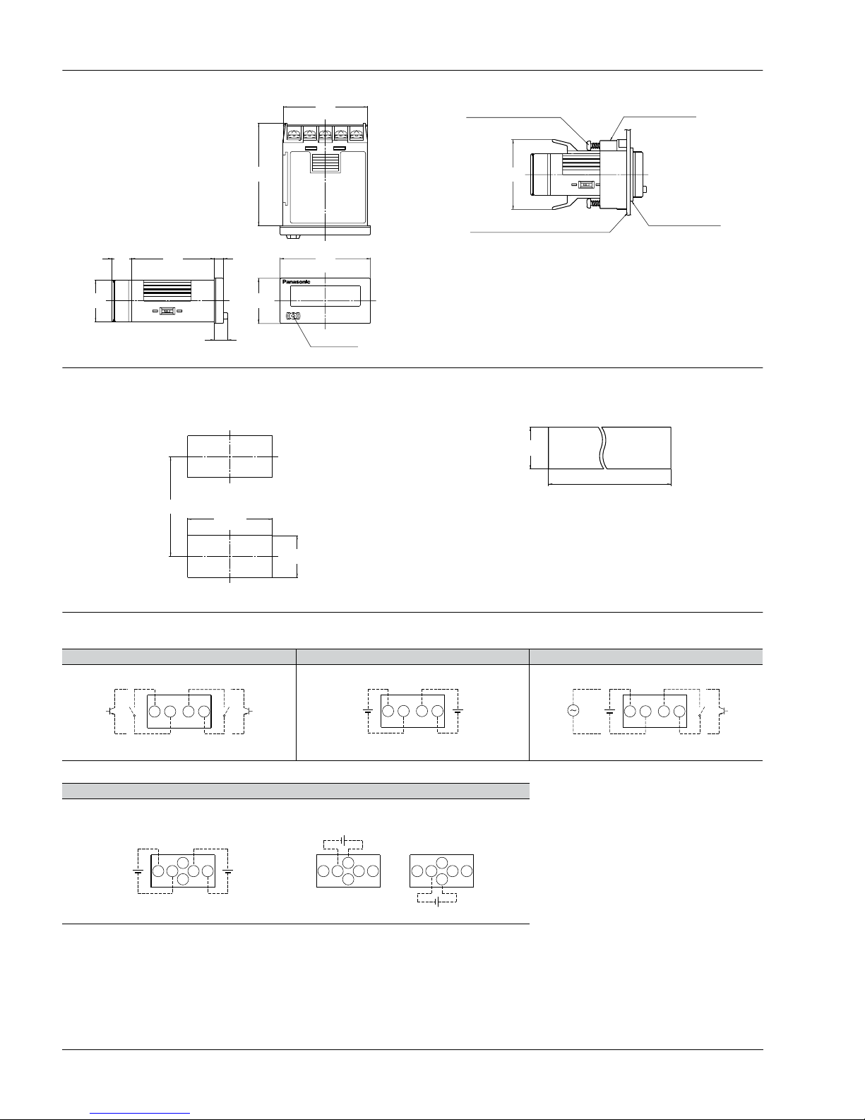
Dimensions
1. Panel mounting type
• External dimensions
1) One-touch installation type
mm inch
General tolerance: ±1.0 ±.039
• Panel installation diagram
Note) When installing to a 4.5 mm .177 inch thick panel, remove the rubber spacer
first.
When installing the one-touch installation type model, make sure
that the installation spring does not pinch the rubber gasket.
To prevent the installation spring
from pinching the rubber gasket:
1. Set the rubber gasket on both
ends of the installation spring
(left and right).
2. Confirm that the installation
spring is not pinching the rubber
gasket, and then insert and fix the
installation spring in place from the
rear of the timer unit.
44.8
1.764
54.4
2.142
5
.197
(44)
(1.732)
10.4
.409
7
.276
22
.866
48
1.890
24
.945
Reset button
COUNTER
LC2H
RESET
Rubber spacer
Panel (1 to 4.5mm
.039 to .177inch
thickness)
CTi Automation - Phone: 800.894.0412 - Fax: 208.368.0415 - Web: www.ctiautomation.net - Email: info@ctiautomation.net
LC2H
102
• Terminal layout and wiring diagrams
1) Standard type
2) Backlight type
Non voltage input type Voltage input type Free voltage input type
Voltage input type
2) Installation frame type • Panel mounting diagram
44.8
1.764
54.4
2.142
5
.197
44
1.732
10.4
.409
7
.276
22
.866
48
1.890
24
.945
Reset button
COUNTER
LC2H
RESET
37
1.457
Mounting screws
(found on mounting frame)
Mounting frame
ATH3803 (included)
Rubber gasket
ATH3804 (included)
Panel
(1 to 4.5mm .039 to .177inch thickness)
• Panel cut-out dimensions
The standard panel cut-out is shown below.
Use the mounting frame (ATH3803) and the rubber packing (ATH3804).
(Only installation frame type.)
• For connected installation (sealed installation)
(Only installation frame type.)
Notes) 1. Suitable installation panel thickness is 1 to 4.5 mm .039 to .177 inch.
2. Waterproofing will be lost when installing repeatedly (sealed installation).
45
1.772
+0.5
0
+.020
0
22.2
.874
+0.5
0
+.020
0
60 min.
2.362 min.
22.2
.874
+0.5
0
+.020
0
A=(48×n-2.5)
A=(1.890×n-.098)
A
+1.0
0
+.039
0
W-R are connected internally.
Count input
2143
Reset input
+V
0V
+V
0V
2143
Count input Reset input
21or 43
Count input Reset input
Backlight
+V0V
<When red><When green>
+V0V
+V
0V
+V
0V
Count input Reset input
12
5
6
34 12
5
6
34 12
5
6
34
CTi Automation - Phone: 800.894.0412 - Fax: 208.368.0415 - Web: www.ctiautomation.net - Email: info@ctiautomation.net
LC2H
103
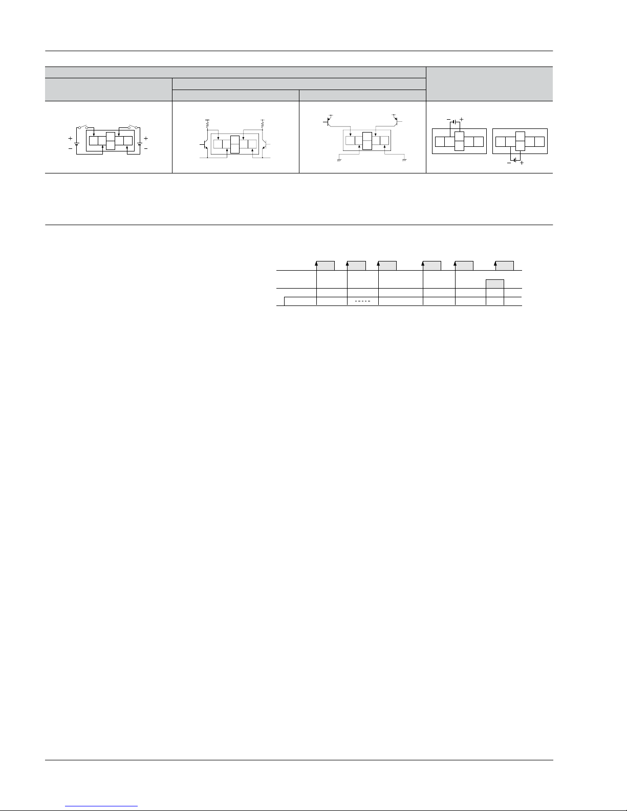
Input method
1. Standard type
Notes) 1. When using contact input, since current flow is small from terminals 1 and 3 on the panel mounting type and terminals e to t and S to F on the PC board
mounting type, please use relays and switches with high contact reliability.
2. When using transistor input, use the following as a guide for which transistors (Tr) to use for inputting. (Collector withstand voltage Q 50 V, leakage current < 1 µA)
Notes) 1. 2 and 4. (The input and reset circuits are functionally insulated.)
2. When using transistor (Tr) input, use the right as a guide. (Collector withstand voltage Q 50 V, leakage current < 1 µA)
3. Be aware that the application of voltage that exceeds the voltage range of the H level to the count input terminal, and the application of voltage to the reset input
terminal, can cause damage to the internal elements.
Non-voltage input type
Panel mounting type PC board mounting type
Contact input
Transistor input
Contact input
Transistor input
NPN transistor NPN transistor
Voltage input type
Free voltage input type
Contact input
Transistor input
NPN transistor PNP transistor
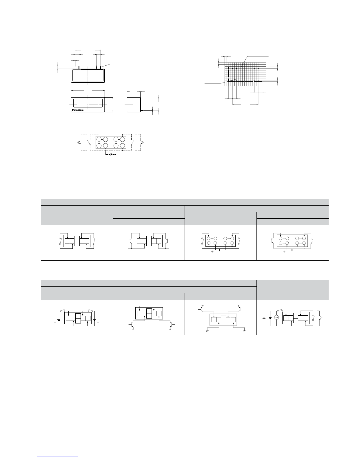
2. PC board mounting type
• External dimensions
• Terminal layout and wiring diagrams
General tolerance: ±1.0 ±.039 mm inch
PC board pattern (BOTTOM VIEW)
General tolerance: ±0.1 ±.004
Note: The AXS212811K is recommended as a compatible connection socket.
LC2HCOUNTER
33.02
±0.3
1.300
±.012
43.4
1.709
17.3
.681
DIP switch × 8
19
.748
15.24
±0.3
.600
±.012
3.3
±0.3
.130
±.012
5.08
±0.3
.200
±.012
0.5
±0.3
.020
±.012
0.3
±0.1
.012
±.004
5.08
±0.3
.200
±.012
0.6
±0.1
.024
±.004
Q-E, }-w, e-t and S-F are connected internally.
An external power supply is required.
Reset inputCount input
15 17 26 28
14 12 3 1
15.24
.600
33.02
1.300
1.9
.075
1.9
.075
5.19
.204
2.54
.100
2.54
.100
8-0.8 dia.
8-.031 dia.
5.08
.200
5.08
.200
5.19
.204
Mounting area
Connection sockets
28 pin DIP terminal
12 34
Reset
input
Count
input
(W and R are connected internally.)
12 34
0V 0V
(W and R are connected internally.)
Reset
input
Count
input
Reset
input
Count
input
3V DC
15
17
14
12
26
28
3
1
Reset
input
Count
input
3V DC
15
17
14
12
26
28
3
1
Reset
input
Count
input
12 34
12 34
Reset
input
Count
input
+V +V
Reset
input
Count
input
12 34
+V +V
12 34
or
or
or
Reset input
Count input
CTi Automation - Phone: 800.894.0412 - Fax: 208.368.0415 - Web: www.ctiautomation.net - Email: info@ctiautomation.net
LC2H
104
2. Backlight type
Notes) 1. Do not reverse the polarities when connecting the DC voltage for the backlight.
2. 2 and 4. (The input and reset circuits are functionally insulated.)
3. When using transistor (Tr) input, use the right as a guide. (Collector withstand voltage Q 50 V, leakage current < 1 µA)
4. Be aware that the application of voltage that exceeds the voltage range of the H level to the count input terminal, and the application of voltage to the reset input
terminal, can cause damage to the internal elements.
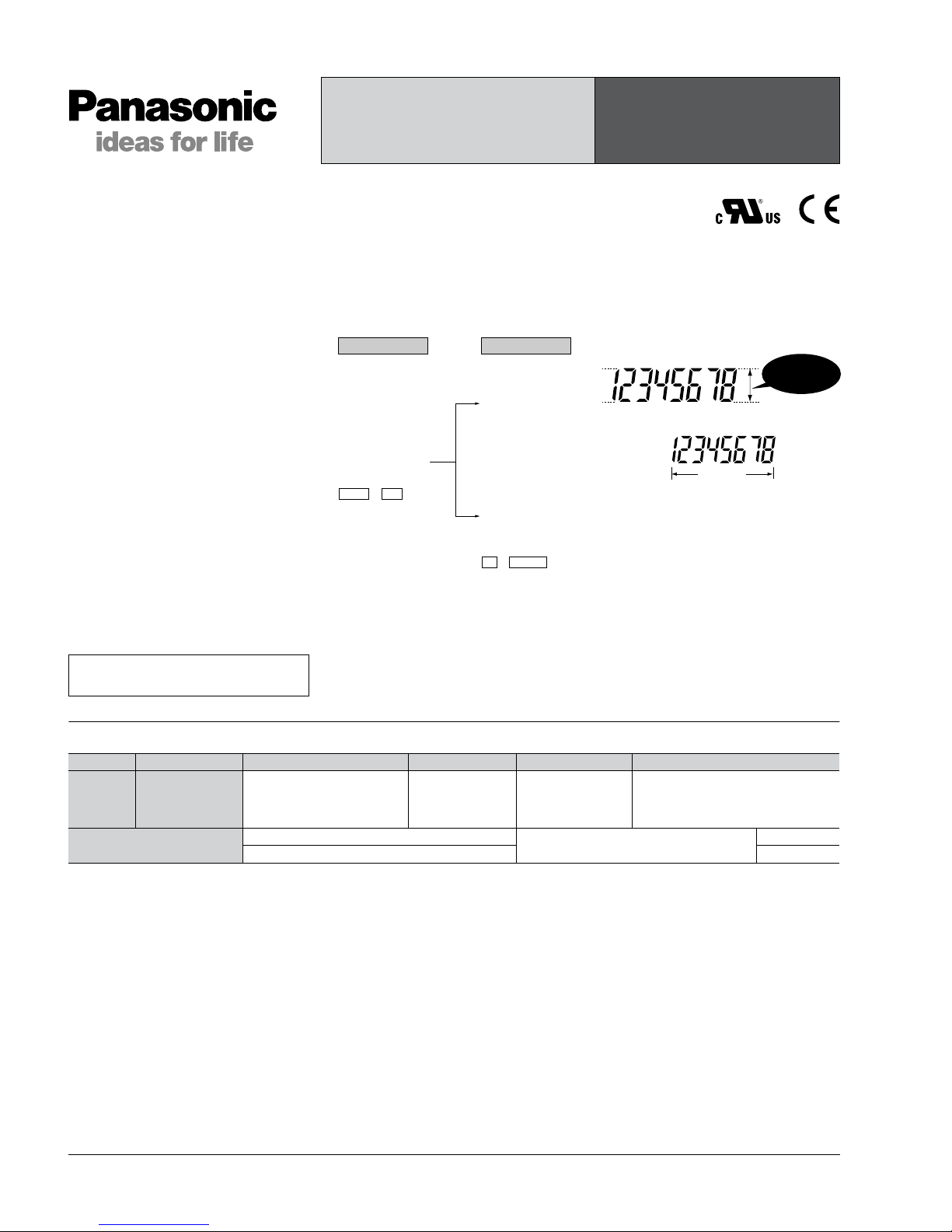
Explanation of operation
Voltage input type
Backlight connection
Contact input
Transistor input
NPN transistor PNP transistor
Reset
input
Count
input
12 34
5
6
0V 0V
Reset
input
Count
input
12 34
+V +V
5
6
12 34
5
6
Reset
input
Count
input
+V +V
12 34
Green Red
24V DC
24V DC
5
6
12 34
5
6
1. Counting takes place when the count
input signal is ON.
2. Counting resumes again when the
count value reaches 99999999 (full scale
value) and then returns to “0” with a new
count input.
3. No measurement takes place when a
reset is input.
1) When reset is ON, resetting takes
place and the count becomes “0”.
2) Press the front reset button when you
want to reset manually (only panel
installation type).
Note) Be aware that battery life will decrease if the
count input or reset input are left ON.
Note) ❇Count becomes “1” when the reset input is turned OFF while the count signal is being input.
Reset input
Count value
Count input
01 0 011
❇
99999999
CTi Automation - Phone: 800.894.0412 - Fax: 208.368.0415 - Web: www.ctiautomation.net - Email: info@ctiautomation.net

LC2H
105
Cautions for use
1. Non-voltage input type
For both panel mounting and PC
board mounting types
1) Never apply v oltage to the non-voltage
input type. This will damage the internal
elements. Also , since there is a possibility
of erroneous operation, do not connect in
parallel the inputs of a non-voltage input
type and another counter from a single
input signal.
2) Since the current flow is very small
from the count input and reset input
terminals (1 and 3 on the panel
mounting type and terminals e to t and
S to F on the PC board mounting type)
please use relays and switches with high
contact reliability.
3) When inputting with an open collector
of a transistor, use a transistor for small
signals in which ICBO is 1 µA or less and
always input with no voltage.
4) When wiring, try to keep all the input
lines to the count and reset inputs as
short as possible and avoid running them
together with high voltage and power
transmission lines or in a power conduit.
Also, malfunctions might occur if the
floating capacitance of these wires
exceeds 500 pF (10 m 32.808 ft. for
parallel wires of 2 mm
2
). When using 2
kHz mode, use with a wiring floating
capacitance of 120 pF (3 m 9.843 ft. for
parallel wires of 2 mm
2
). In particular,
when using shielded wiring, be careful of
the capacitance between wires.
PC board mounting type
1) For external power supply use
manganese dioxide or lithium batteries
(CR type: 3V).
2) Always reset after external power is
applied and confirm that the display
reads “0”.
3) Make the wiring from the battery to the
counter unit as short as absolutely
possible. Also, be careful of polarity.
4) Calculate battery life with the following
formula.
t = A/I
t: battery life [h]
I: LC2H current consumption [mA]
A: battery capacity until minimum
operation voltage is reached [mAh]
5) Hand solder to the lead terminal. Do
not dip solder. With the tip of the
soldering iron at 300°C 572°F perform
soldering within 3 seconds (for 30 to 60
W soldering iron).
2. Voltage input type
1) Be aware that applying more than 30 V
DC to count input terminals 1 and 2,
and reset input terminals 3 and 4 will
cause damage to the internal elements.
2) For external resetting use H level
(application of 4.5 to 30 V DC) between
reset terminals 3 and 4 of the rear
terminals. In this case, connect + to
terminal 3 and – to terminal 4. This is
the valid polarity; therefore, the counter
will not work if reversed.
3) When wiring, try to keep all the input
lines to the count and reset inputs as
short as possible and avoid running them
together with high voltage and power
transmission lines or in a power conduit.
Also, malfunctions might occur if the
floating capacitance of these wires
exceeds 500 pF (10 m 32.808 ft. for
parallel wires of 2 mm
2
).
3. Free voltage input type
1) Use count input terminals 1 and 2 for
free voltage input and reset terminals 3
and 4 for non-voltage input.
2) Be aware that the application of
voltage that exceeds the v oltage range of
the H level to the count input terminal,
and the application of voltage to the reset
input terminal, can cause damage to the
internal elements.
3) Since the current flow is very small
from reset input terminal 3, please use
relays and switches with high contact
reliability.
4) When inputting a reset with an open
collector of a transistor, use a transistor
for small signals in which ICBO is 1 µA or
less and always input with no voltage.
5) To reset externally, short reset input
terminals 3 and 4 on the rear.
6) Input uses a high impedance circuit;
therefore, erroneous operation ma y occur
if the influence of induction voltage is
present. If you plan to use wiring for the
input signal that is 10 m or longer (wire
capacitance 120 pF/m at normal
temperature), we recommend the use of
a CR filter or the connection of a bleeder
resistor.
4. How to reset multiple panel
mounting type counters all at once
(input is the same for count)
Non-voltage input type
Notes) 1. Use the following as a guide for choosing
transistors used for input (Tr).
Leakage current < 1 µA
2. Use as small a diode (D) as possible in the
forward voltage so that the voltage betw een
terminals 3 and 4 during reset input meets
the standard value (0.5 V).
( At IF = 20 µA, forward voltage 0.1 and
higher.)
Voltage input type
Note) Make sure that H (reset ON) level is at least 4.5
V.
5. Backlight luminance
To prevent varying luminance among
backlights when using multiple Backlight
types, please use the same backlight
power supply.
6. Environment for use
1) Ambient conditions
• Overvoltage category II, pollution level 2
• Indoor use
• Acceptable temperature and humidity
range: –10 to +55°C, 35 to 85%RH (with
no condensation at 20°C)
• Under 2000 m elevation
2) Use the main unit in a location that
matches the following conditions.
• There is minimal dust and no corrosive
gas.
• There is no combustible or explosive
gas.
• There is no mechanical vibration or
impacts.
• There is no exposure to direct sunlight.
• Located away from large-volume
electromagnetic switches and power
lines with large electrical currents.
3) Connect a breaker that conforms to
EN60947-1 or EN60947-3 to the voltage
input section.
4) Applied voltage should be protected
with an overcurrent protection device
(example: T 1A, 250 V AC time lag fuse)
that conforms to the EN/IEC standards.
(Free voltage input type)
3
or
D
Tr
4 3 4 3 4
D D
3
or
+V
+V
R
Tr
4 3 4 3 4 3 4
2
2
5
2
Green Red
5
6
2
6
24V DC 24V DC
CTi Automation - Phone: 800.894.0412 - Fax: 208.368.0415 - Web: www.ctiautomation.net - Email: info@ctiautomation.net
LC2H
106
Product types
Note: Mounting frame and rubber gasket are not included.
PRESET COUNTER
LC2H
Counter
No. digits Counting speed Output mode Output Operating voltage Part No.
8 digits
30 Hz/5 kHz
switchable
• Maintain output/hold count
• Maintain output/over count
• One shot/over count
• One shot/recount
Transistor (1a) 24 V DC LC2HP-FEW-B-DC24V
Options
Mounting frame
Use for waterproofing (front panel surface)
ATH3803
Rubber gasket ATH3804
Features
1. Preset function equipped in half
size (24 × 48 mm 0.945 × 1.890 inch).
2. Display has backlight for instant
recognition.
3. 8.7 mm 0.343 inch Character Height
(previously 7 mm 0.276 inch)
Easy-to read character height increased
from 7 mm to 8.7 mm 0.276 inch to 0.343
inch.
4. Plenty of Digits
5. Counting Speed Switchable
between 30 Hz and 5 kHz
6. Conforms to IP66 Protective
Construction (Front panel surface)
Weatherproofing supported by using
optional mounting frame and rubber
gasket
7. Includes reassuring lock mode and
lock switch to prevent erroneous
operation.
8. Screw terminals are constructed to
protect fingers to ensure safety.
9. Compliant with UL, c-UL and CE.
RoHS Directive compatibility information
http://www.nais-e.com/
Green or (Red)
(backlight)
Red or (Green)
(backlight)
Red or (Green)
(backlight)
(Lit or Flashing)
(Lit or Flashing)
Counting upCounting
Green or Red can
be selected at setup.
Lit or Flashing can
be selected at setup.
8.7mm
.343inch
8 digits
CTi Automation - Phone: 800.894.0412 - Fax: 208.368.0415 - Web: www.ctiautomation.net - Email: info@ctiautomation.net
LC2H
107
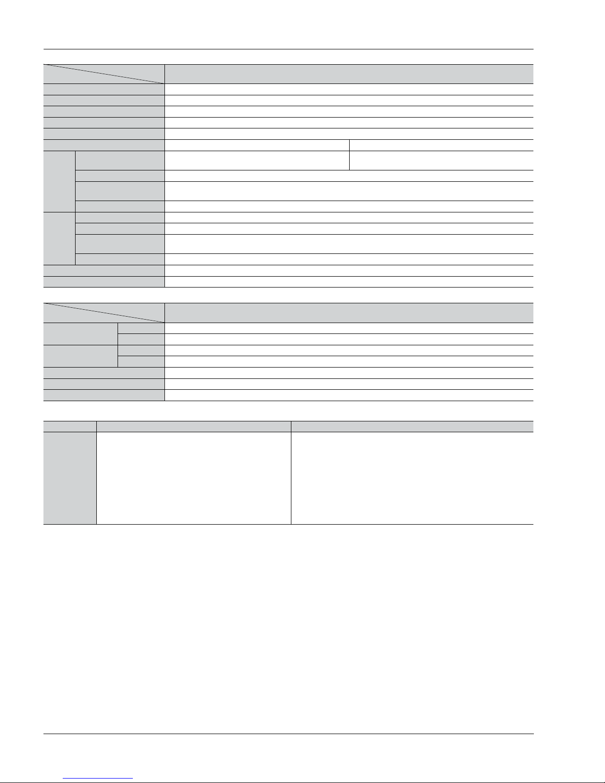
Specifications
* The factory default preset value is set to 1000000.
Applicable standard
Item Descriptions
Rating
Rated operating voltage 24 V DC
Rated power consumption Max. 1.5 W
Rated control capacity 100 mA 30 V DC
Input mode Addition/Subtraction (selectable by front switch)
Max. counting speed 30 Hz/5 kHz (selectable by slide switch on side)
Counting input
Min. input signal width: 16.7 ms at 30 Hz/0.1 ms at 5 kHz,
ON time : OFF time = 1 : 1
Reset input Min. input signal width: Min. 30 ms
Input signal
• Non-voltage input using contacts or open-collector connection
• Input impedance; when shorted: Max. 1 kΩ, when open: Min. 100 kΩ
• Residual voltage: Max. 2 V
Output mode
• Maintain output/hold count • Maintain output/over count
• One shot/over count • One shot/recount
(Selectable by front switch)
Display method
7-segment LCD
(Switch between red and green for backlight, and between lit and flashing for count up.)
Digit
–9999999 to 99999999 (–7 digits to +8 digits)
(0 to 99999999 for preset value)
Memory EEP-ROM (Overwriting times: 105 operations or more)
Contact arrangement 1 Form A (Open collector)
Electrical life (contact) 107 operations (at rated control voltage)
Electrical
Allowable operating voltage range 85 to 110% of rated operating voltage
Break down voltage (Initial value) Between input and output: 1,500 V AC, for 1 min.
Insulation resistance (Initial value) Between input and output: 100 MΩ (at 500 V DC)
Mechanical
Functional vibration resistance 10 to 55 Hz (1 cycle/min), Single amplitude: 0.15 mm (10 min. on 3 axes)
Destructive vibration resistance 10 to 55 Hz (1 cycle/min), Single amplitude: 0.375 mm (1 hr. on 3 axes)
Functional shock resistance Min. 98 m/s2 (4 times on 3 axes)
Destructive shock resistance Min. 294 m/s2 (5 times on 3 axes)
Operating
conditions
Operation temperature –10 to 55°C +14 to +131°F (without frost or dew)
Storage temperature –25 to +65°C –13 to +149°F (without frost or dew)
Ambient humidity 30 to 85% RH (at 25°C 77°F, non-condensing)
Protective construction IP66 (front panel with mounting bracket and rubber gasket)
EMC
(EMI)EN61000-6-4
Radiation interference electric field strength
Noise terminal voltage
(EMS)EN61000-6-2
Static discharge immunity
RF electromagnetic field immunity
EFT/B immunity
Conductivity noise immunity
Power frequency magnetic field immunity
EN55011 Group1 ClassA
EN55011 Group1 ClassA
EN61000-4-2 4 kV contact
8 kV air
EN61000-4-3 10 V/m AM modulation (80 MHz to 1 GHz)
10 V/m pulse modulation (895 MHz to 905 MHz)
EN61000-4-4 2 kV (power supply line)
1 kV (signal line)
EN61000-4-6 10 V/m AM modulation (0.15 MHz to 80 MHz)
EN61000-4-8 30 A/m (50 Hz)
CTi Automation - Phone: 800.894.0412 - Fax: 208.368.0415 - Web: www.ctiautomation.net - Email: info@ctiautomation.net
 Loading...