


NVHD650
Table of contents
 Loading...
i ' N il ii'i nvi: fife'' r i ì;V:":№':S4ì S
Video Cassette Recorder
NV-HD650
Series
n ^ SUPEB DRIVE A!
J-CODt )NmUG£NT COimOL SYSTEM
/QT5984
VHS
PAL NTSC 4,43
Before attempting to connect, operate or adjust this product,
please read these instructions completely.
Dear Customer
May we take this opportunity to thank you for purchasing
this Panasonic Video Cassette Recorder.
We would particularly advise that you carefully study the
Operating Instructions before attempting to operate the unit
and that you note the listed precautions.
G-Code Programming System
Programming is now easier than ever; simply enter the
G-Code number provided in the programme schedule
column carried by newspapers and magazines.
•G'Code is a trademark applied for by Gemstar
Development Corp. G-Code system is manufactured
under licence from Gemstar Development Corporation.
Al Crystal View Control
Al circuit for automatic tape calibration and optimizing of
playback characteristics.
During playback the contrast of tapes recorded with good
level is automatically optimized.
Contents
IMPORTANT
Your attention is drawn to the fact that
recording of pre-recorded tapes or discs
or other published or broadcast material
may infringe copyright laws.
WARNING
TO REDUCE THE RISK OF FIRE OR
SHOCK HAZARD, DO NOT EXPOSE
THIS EQUIPMENT TO RAIN OR
MOISTURE.
NV-HD650A: Australian model
NV-HD650EA: New Zealand model
FOR YOUR SAFETY
■ DO NOT REMOVE OUTER COVER.
To prevent electric shock, do not remove
cover. No user serviceable parts inside. Refer
servicing to qualified service personnel.
HQ (High Quality) Picture System
Video recorders carrying the HQ symbol mark feature the
new VHS High Quality Picture System. This system
assures complete compatibility with VTRs that use the
conventional VHS system.
Controls and Connection Sockets
Infra-red Remote Controller
.........
Connections
...............................................................
8
Tuning the TV to your VTR ..................................... 9
Setting the Remote Controller for Operation
of your TV
..............................
.....
..........................
11
Language Setting of On Screen Display
................
12
Setting the Clock of the VTR .................................. 13
Storing TV Broadcasts into your VTR
...................
14
Preparations for G-Code Programming
...................
16
Settings Using On Screen Display
...........................
18
Playback
..................................................................
20
Manual Recording..................................................... 22
Timer Recording ....................................................... 24
•G* *Code Programming ............................................ 26
Editing ....................................................................... 27
•Assembly Editing ...................................................... 27
• insert Editing ............................................................ 28
•Audio Dubbing........................................................... 29
Other Functions........................................................ 30
Before Requesting Service
.....................................
33
Precautions............................................................... 36
Specifications...................................................................... 37
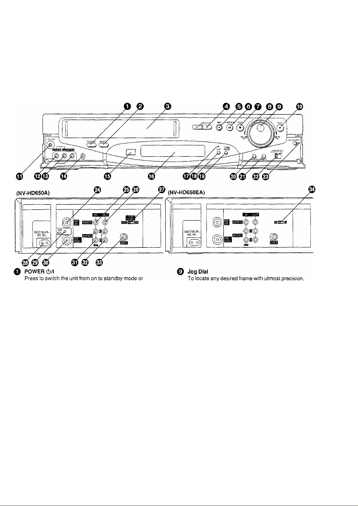
Controls and Connection Sockets
This gives a detailed explanation of the function of each button, switch and connection socket.
vice versa. In standby mode, the unit is still connected
to the mains.
0 EJECT
To eject a video cassette.
0 Cassette Compartment
Insert a video cassette here.
o
To select the required programme position (TV
station).
© REC
To start a recording.
© PAUSE/STILL
in the stop mode: Still picture (Jog/Shuttle mode).
During playback: Still picture (Jog/Shuttle mode).
During recording; To interrupt recording,
O STOP
To stop any playback or recording.
© Shuttle Ring
In the stop mode: To rewind or fast forward the tape.
In the playback mode:
To search picture backward or
forward.
In the still playback mode:
To adjust playback speed backward
or forward.
In the rewind or fast forward mode:
To obtain high speed picture.
® PLAY
To start playback. “O” is lit.
For the repeat playback function.
0 SYNC, EDIT
To connect a movie camera or another VTR equipped
with synchronized editing capability.
0 VIDEO IN (AV2)
To connect the video cable to a movie camera or to
another VTR.
0 AUDIO IN (AV2)
To connect the audio cable to a movie camera or to
another VTR.
0 MIC
To connect a microphone for recording. Once
connected, this socket has priority.
0 Infra-red Remote Control Receiver Window
0 Display
0 CVC Indicator
When the CVC function is on, this indicator is lit.

Controls and Connection Sockets
C
.o
-S-
b
CO
Q)
Q
CVC {Crystal View Control)
ON; Using the CVC function, playback and
recording are performed in the state which
achieves optimum picture quality in light of
characteristics of a tape.
•The CVC indicator is lit.
•This control should normally be left in the ON
position.
OFF; Turn off the CVC function.
•The CVC indicator is not lit.
•With certain tapes, the OFF position may
result in a better picture.
0 TIMER REC
To turn the timer recording function on and off.
H is lit or not lit.
Once operating timer recording function, the normal
VTR operation is not possible unless this button is set
to off.
0 AUDIO DUB
To set up the VTR for audio dubbing.
A,DUB is appeared on screen display.
0 INSERT
To set up the VTR for insert editing.
INSERT is appeared on screen display.
© NTSC SELECT
Set according to the colour TV system.
NTSC P,8.: When receiving PAL signals.
For TV’s that can only receive PAL
signals.
4.43: When receiving NTSC 4.43 signals.
For TV’s that can receive NTSC 4.43
signals.
© COUNTER RESET
T0 reset the tape counter (elapsed time) to “0:00.00”.
•The tape counter is automatically reset to “0;00.00”
when a video cassette is inserted.
© RFIN
To connect to the external aerial.
© VIDEO IN (AV1)
To connect a video cable from a Movie Camera or
another video recorder.
© VIDEO OUT
To connect a video cable to a TV or another video
recorder.
@ TEST SIGNAL (NV-HD650A only)
The test signal is transmitted on channel AU37.
© ACIN-
T0 connect to the main power supply.
© CH ADJ. (NV-HD650A only)
To adjust the RF transmitting channel AU31 -43.
© RFOUT
To connect to the aerial terminal on a TV set.
© AUDIO IN (AVI)
To connect an audio cable from a Movie Camera or
another video recorder.
© AUDIO OUT
To connect an audio cable to a TV or another video
recorder.
© EDIT
©
By connecting the optional Editing Controller
(VW-EC300E/VW-EC31OE) to this socket, such
editing functions as Assemble Editing, Insert Editing
and Audio Dubbing can be performed more quickly
and efficiently between two VTRs or between a VTR
and a movie camera.
Video Playback Channel Selector
(NV-HD650EA only)
To select the video playback channel.
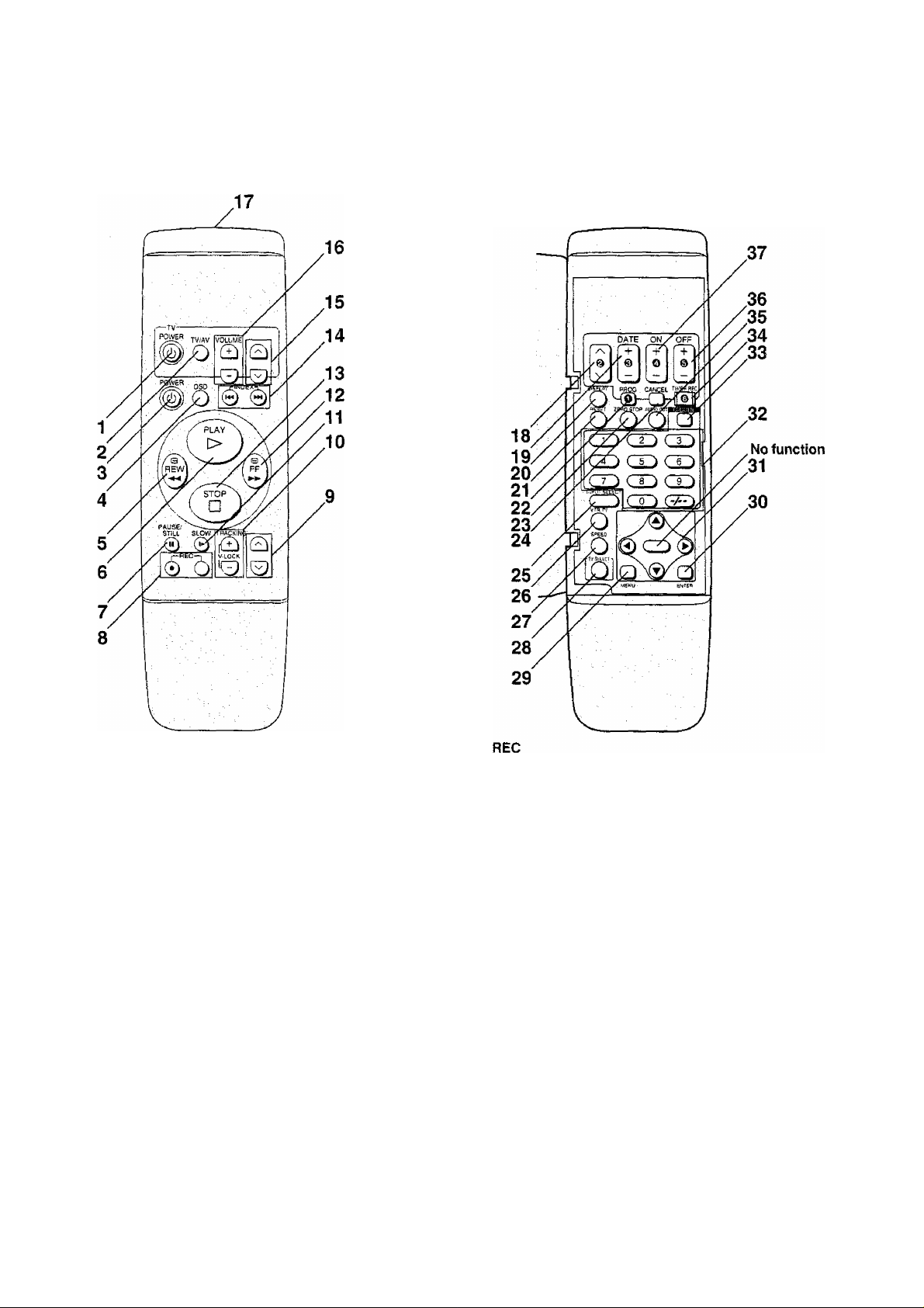
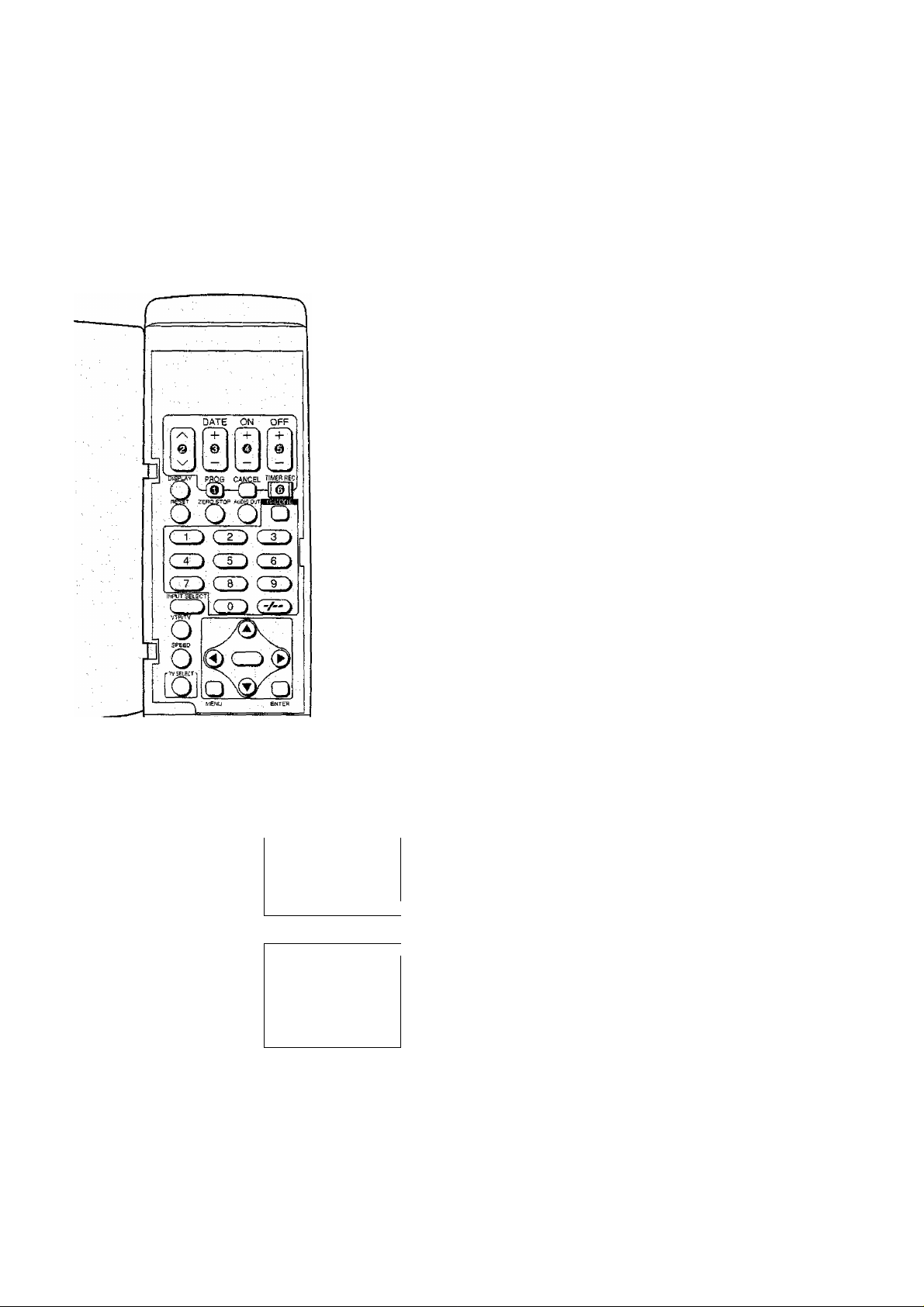
Infra-red Remote Controller
POWER (TV)
To switch the TV from on to standby mode or vice
versa. In standby mode, the TV is still connected to the
mains.
•With some TV models, it may only be possible to
switch the TV to standby mode using this button.
In this case, use TV/AV or s/ /\ (TV) to switch the
TV on.
TV/AV
To select the TV input.
POWER (VTR)
To switch the VTR from on to standby mode or vice
versa, in standby mode, the VTR is still connected to
the mains.
OSD
For the On Screen Display Function.
REW (REWIND)
In the stop mode; To rewind the tape
In the playback mode: To search backward
In the rewind mode: To obtain high speed picture
is lit.
PLAY
To start playback. “O" is lit.
For the repeat playback function,
PAUSE/STILL
During playback: Still picture.
During recording: To interrupt recording.
To start a recording.
• Press both buttons simultaneously.
9 V/N(VTR)
To select the required programme position (TV station)
of the VTR.
10 TRACKING/V-LOCK
For manual tracking adjustment
The + and - buttons are used to adjust the tracking
when, for example, noise bars on the picture are better
removed manually than by the automatic digital
tracking control. After making a manual adjustment,
press both buttons together to return to automatic
digital tracking control.
For slow tracking adjustment
When noise bars appear during Still or Slow playback,
switch over to slow playback and adjust with the + or
- Button to reduce the noise bars.
For vertical locking adjustment
Use the + and - buttons to minimize any vertical jitter
during still-picture playback.
11 SLOW
For the slow motion playback function, is lit.
12 FF (FAST FORWARD)
In the stop mode: To fast forward the tape
In the playback mode: To search forward
In the fast forward mode: To obtain high speed picture
“!>!>’’ is lit.

Infra-red Remote Controller
c
o
•C3
.Q-
o
CO
Qi
Q
13 STOP
To stop any playback or recording.
14 INDEX
For the index search function.
15 \//\(TV)
To select the required programme position {TV station)
of the TV,
16 VOLUME
To adjust the volume of the TV.
17 Infra-red Transmitter
18 s/ /\
To programme a timer recording.
19 DATE
To programme a timer recording.
20 DISPLAY
To change the indication on the VTR Display.
p^Clock^Counter-^Remaining Tape Time —|
21 RESET
To reset the tape counter (elapsed time) to “0:00.00”.
•The tape counter is automatically reset to “0:00,00”
when a video cassette is inserted.
22 PROG
To set and check timer programmes.
23 ZERO STOP
For the zero stop function.
24 CANCEL
To cancel the settings made for a timer recording.
25 INPUT SELECT
To select the A1 or A2 external recording source.
26 VTR/TV
To select the VTR mode or TV mode.
(NV-HD650A: No function.)
27 SPEED
To select the tape speed desired for recording.
SP gives the best picture quality.
LP gives the longest recording time.
28 TV SELECT
To set the remote controller for operation of the TV.
29 MENU
To make OSD menu appear on the TV screen.
30 ENTER
To confirm the selection, or to store.
31
A
▼
To make selections from On Screen Display.
32 Programme Position Selector Buttons
•To select the programme positions (1-99).
9: CO
19: (-/--)—( 1 )—C 9 j
• To programme a G-Code number.
33 G-Code
For the G-Code programming.
34 TIMER REC
To turn the timer recording function on and off.
[3 is lit or not lit,
Once operating timer recording function, the norma!
VTR operation is not possible unless this button is set
to off.
35 AUDIO OUT
To select the desired sound mode.
At the every push of this button, the audio output mode
changes as follows,
»Stereo->Left—»-Right^Norma! audio track-
c:
The Left (L) and Right (P) Indicators show which sound
mode is selected in the following way.
Stereo; Both the Left (L) and Right (R) Indicators
appear.
Left: The Left (L) Indicator appears.
Right: The Right (R) Indicator appears.
Normal: Both the Left (L) and Right (R) Indicators
don’t appear.
36 OFF
To programme a timer recording.
37 ON
To programme a timer recording.
Power Source for the Remote Controller
The remote controller is powered by 2 “AA”, “UM3" or “R6”
size batteries. The life of the batteries is about one year,
although this depends on the frequency of use.
Precautions for Battery Replacement
•Load the new batteries with their polarity (© and ©)
aligned correctly.
•Do not apply heat to the batteries, or an internal
short-circuit may occur.
•If you do not intend to use the remote controller for a long
period of time, remove the batteries and store them in a
cool and dry place.
• Remove spent batteries immediately and dispose of
them.
•Do not use an old and a new battery together, and never
use an alkaline battery with a manganese battery.
Installing the Batteries
Connections
This tells you how to connect with an aerial, TV, etc.
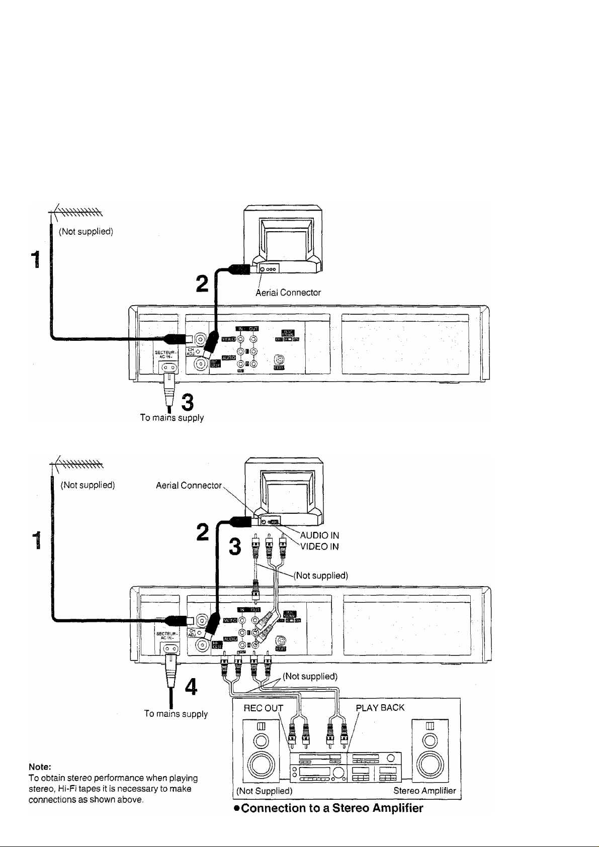
Basic Connections
The following connections are required to record and play
back the VTR through TV set:
Aerial TV Set (Not supplied)
Connection to a TV Set with the Audio/Video Input Sockets
Aerial
TV Set (Not supplied)
Tuning the TV to your VTR
Connections
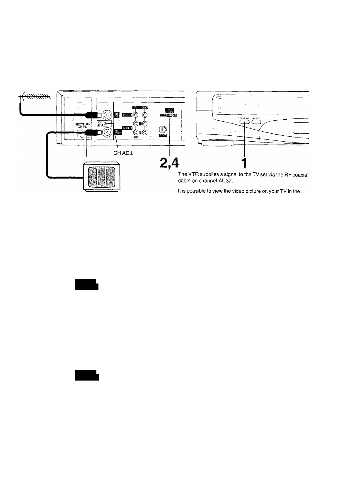
Tuning the TV to your VTR
NV-HD650A
Operations
1,3
same way that you watch TV broadcasts.
If you have connected the VTR to the TV through the video
and audio sockets then you do not need to follow the
procedure mentioned below.
CO
1
CZ)
Turn on the TV and VTR.
TEST
SIGNAL
To generate a test pattern, set TEST
SIGNAL to ON.
Set the TV to an unused position which you
wish to use for your video playback.
TEST
SIGNAL
Set TEST SIGNAL to OFF.
Note:
The test signal is transmitted on video channel AU37. If you
are encountering interference from a TV broadcast on this
video channel, you may readjust to another free channel
(AU31 -43) by using the CH ADJ. screw which is located on
the rear of the VTR.
Please note that if the CH ADJ. screw is used then you will
have to retune your TV to the test signal as in item 2 to 4
above.
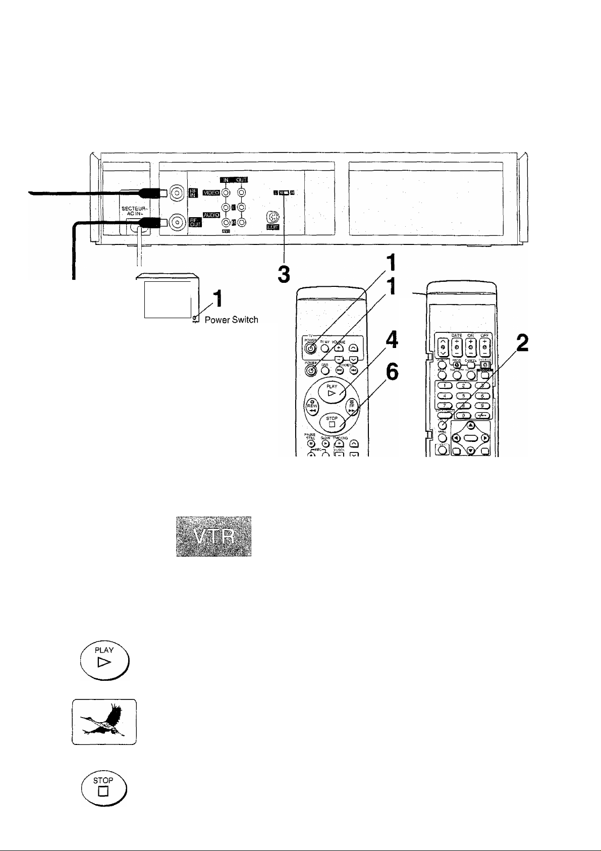
NV-HD650EA
-
. ^
_______
_
Select the channel or AV,
It is possible to view the video picture on your TV in the
same way that you watch TV broadcasts.
If you have connected the VTR to the TV through the
video and audio input sockets then you do not need to
foliow the procedure mentioned below. Instead, simply
select AV mode on the television.
Operations Display Symbol
1
TV
POWER
POWER
Turn on the TV and VTR.
VTtVTV
o
Select the VTR mode.
iimsi
Select the video playback channel which is
not occupied with any TV station.
H: Channels
L: Channel 2
Insert a pre-recorded cassette tape and
press PLAY.
Select a programme number on the TV set
which you wish to use as the video viewing
channel. Then tune in the TV to the picture
from the cassette tape currently playing.
Stop the playback.
Setting the Remote Controller
for Operation of your TV
Tuning the TV to your VTR
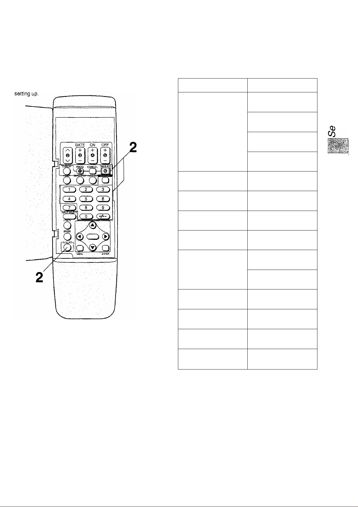
Setting the Remote Controller
for Operation of your TV
You can operate some manufacturer of TVs (see following
table) using the supplied Remote Controller after this
Preparation
Install the batteries in the remote controller. See page 7.
Operations
1
Turn on the TV.
Press corresponding operation button
to your TV manufacturer (see following
table) while keeping TV SELECT
pressed.
•If setting is correct, TV will be turned off
automatically.
TV Manufacturer
Operation Button
Panasonic/National
TV SELECT DISPLAY
O • 0
TVSEIKT ppQQ
O " ®
TV SELECT CANCEL
O * □
TV^CT RE0
o " a
SONY
TV SELECT
O
TOSHIBA
TV SELECT
O ^ CO
JVC
TV SELECT
O
HITACHI
TV SELECT
O *CiD
MITSUBISHI
TV SELECT
O " ^
TV SELECT
O
SHARP
TV SELECT
o ^
PHILIPS
TV SELECT
O ^ CO
NEC
TV SELECT
O -CO
SANYO
TV SELECT
O -eu
When the TV manufacturer Is Panasonic/National or
MITSUBISHI;
When the TV's power is turned off in step 2 above, turn it
back on and adjust the TV’s volume using this remote
controller. The volume can be adjusted if the operation
button matches the manufacturer of TV.
If it is not possible to adjust the TV's volume, try pressing
the other operation button to match the manufacturer of TV
again until the volume can be adjusted.
Note:
Some TV models cannot be operated using this remote
controller.
11
Language Setting of On Screen Display
Preparations
•Confirm that the TV is on and the VTR viewing channel is
selected.
•Turn on the VTR.
• Press VTR/TV to select the VTR mode.
(NV-HD650EA only)
To select the Desired Language
Select one of the two languages displayed; English and
Russian.
1 Press MENU. On Screen Display
OBD MENU
•LANGUAGE
□
MENU
CLOCKSET
TUNER PRESET
Q-COOE CH SET
OPTION
DEMONSTRATION
: SELECT lilD.ENTER
END :MENU
L_
_J
2 Select LANGUAGE.
0
□
OSO MENU
•LANGUAGE
CLOCKSET
TUNER PRESET
0
OPCODE ONSET
OPTION
DEMONSTHATtON
ENTER
SELECT -.BD.ENTER
END :MENU
3 Select the desired language.
0
0
•engush
PyCCKUM
4 Press MENU twice.
□
To View a Demonstration
1 Press MENU.
□
OSD MENU
• LANGUAGE
CLOCK SET
7UNEH PRESET
Q.COOE CH SET
OPTION
DEMONSTRATION
2 Select DEMONSTRATION.
0
0
O
ENTER
OSD MENU
LANGUAGE
CLOCK SET
TUNER PRESET
G.CODE CH SET
OPTION
• DEMOMSTRATIOK
SELECT ;QQ. ENTER
END :MENU
• During Demonstration mode, all the On Screen
Displays are displayed one after the other at about five
second intervals.
3 Press MENU to stop the Demonstration.
□
MENU
Note:
The Menu Screen has a blue background. However, if there
is no signal input during AV1/AV2 is selected, the Menu
Screen may change to black and white when MENU is
pressed. This does not indicate a malfunction,
if this happens, either input a signal or select other
programme position.
MENU
Loading...