


ORDER NO. VRD0008027C2
Video Cassette Recorder
NV-SJ407EE / NV-SJ207EE
Z-MECHANISM
SPECIFICATIONS
© 2000 Matsushita Electric Industrial Co., Ltd. All rights reserved. Unauthorized copying and distribution is a violation of law.
http://cxema.ru
1. INTRODUCTION
This service manual contains technical information which will allow service personnel to understand and service this model.
If the circuit is changed or modified, this information will be followed by supplementary service manual to be filed with original service manual.
Note:
1.Adjustment procedures, Disassembly Procedures and Assembly Procedures for Mechanism Chassis are separate volume from this service manual. / Please refer to the service manual for Z-Mechanism Chassis. (Order No. VRD9802005C2)
2.The Model No. is indicated on the Schematic Diagram and Circuit Board Diagrams as follows.
Model No. |
Indication Mark |
NV-SJ407EE |
(SJ407) |
NV-SJ207EE |
(SJ207) |
2. GENERAL DESCRIPTIONS
2.1. SERVICE INFORMATION
2.1.1. MICROPROCESSOR RESET
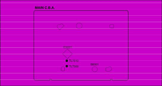
When the Microprocessor IC6001, MAIN C.B.A. and/or Back-up Battery B6001 are replaced, read following procedure carefully and proceed it.
Reasons:
There is a RAM in the IC6001, which is backing up:
1.TV Tuning Data.
2.PG shifter Adjustment Data
3.Option Setting Data
When IC6001, MAIN C.B.A. and/or Back-up Battery B6001 are replaced, all above listed data become not available.
These data are backing up by using the power source of: AC connected: AC Power source
AC Disconnected: Back-up Battery B6001
Method:
Before replacing IC6001, MAIN C.B.A. and/or B6001:
1. Take a note that stored TV broadcasts channels.(Because , its user may store TV broadcasts by manually other than "Auto Tuning" operation and it is also erased.)
After replacing IC6001, MAIN C.B.A. and/or B6001:
1.Turn on the VCR.
2.Connect a jumper wire between TL7509 and TL7510 for 1 second to reset IC6001.
After resetting IC6001:
1. Store TV broadcasts channels by Auto/Manual Tuning using the On Screen Display according to note which taken before replacing IC6001, MAIN C.B.A. and/or B6001.
http://cxema.ru
2.Set the Direct Rec function to OFF using On Screen Display if necessary. / (Because, Direct Rec function is set automatically to ON after resetting IC6001.) / [Direct Rec Function] / OFF: Normally set at this position. / ON: This setting enables Direct Rec. / AV1 Input(A1) becomes exclusive channel for Direct Rec.
3.Perform the PG SHIFTER ADJUSTMENT. / (Refer to the Electrical Adjustment Procedures.)
Note:
1.It should be performed before tuning.
2.Do not cut off the power source during reset.
Fig. S1
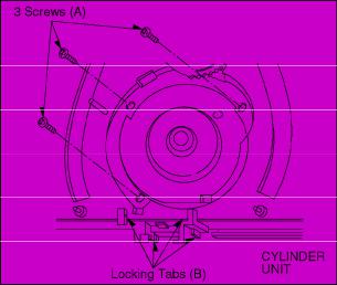
2.1.2. CYLINDER UNIT REPLACEMENT
1.CYLINDER UNIT REPLACEMENT
A.Remove the mechanism unit from MAIN C.B.A./Chassis by referring “SECTION 3. Disassembly Method”.
B.Remove the 3 screws (A) of the CYLINDER UNIT with a screw driver.
C.Unlock the 4 locking tabs (B) and disconnect the Cylinder fiexible card from the FPC Holder.
D.Remove the CYLINDER UNIT.
CAUTION:
Handle the Cylinder flexible card with care. When it damaged, you should replace whole Cylinder unit.
Fig. S2
http://cxema.ru
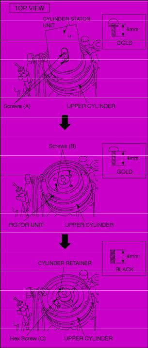
2.UPPER CYLINDER DISASSEMBLY
A.Remove 2 screws (A).
B.Remove the Cylinder Stator Unit.
C.Remove 2 screws (B).
D.Remove the Cylinder Rotor Unit.
E.Loose Hex screw (C) (1.5 mm) and remove the CYLINDER RETAINER.
F.Remove the Upper Cylinder.
Fig. S3
http://cxema.ru
3. UPPER CYLINDER ASSEMBLY
When reassembling, perform the steps in the reverse order.
Notes:
1.Install the Cylinder Retainer so that the 2 holes on top of the Cylinder Retainer are at right angles with the Cylinder Connection.
2.Tighten the Hex screw (C) (1.5 mm) while pressing down on top of the Cylinder Retainer.
Fig. S4
http://cxema.ru
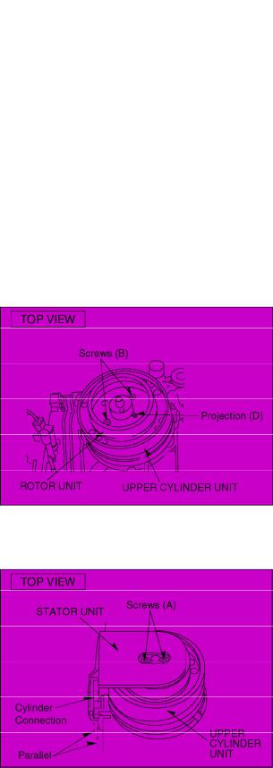
3.Install the Cylinder Rotor Unit so that the inner hole of the Cylinder Rotor Unit fits to the small projection (D) on top of the Upper Cylinder.
4.Tighten 2 screws (B).
Fig. S5
5.Install the Cylinder Stator Unit so that the rear side of the Cylinder Stator C.B.A. is parallel with the Cylinder Connection.
6.Tighten 2 screws (A).
Fig. S6
7. Confirm the PG SHIFTER ADJUSTMENT with the alignment tape (PAL: VFJ8125H3F) and adjust it if necessary.
http://cxema.ru

2.1.3. CHECKING OF MAIN C.B.A.
When servicing the MAIN C.B.A., take out the MAIN C.B.A. and mechanism from the frame and turn over. Fig. S7
2.1.4. FLAT CARD CABLE INSTALLATION
When installing the Flat Card Cable on the connector, install the Flat Card Cable with the cable contacts facing the connector contacts.
Fig. S8
2.2. REMOVAL OF CASSETTE TAPE
There are 2 ways to remove a cassette tape.
1.Service Information Display Operation
A.Press the FF and EJECT keys simultaneosly for 3 seconds and set the Service Mode 7.
B.Press STOP key in order to rotate the Loading Motor for unloading operation. (Pay an attention of tape slack)
2.Manual Operation
A.Disconnect the AC Mains Lead and remove the Top Panel.
B.Rotate the Main Cam Gear clockwise until the Loading Posts move to fully unloaded position as shown in Fig. S9. (Tape is remaining)
Fig. S9
http://cxema.ru
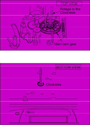
C. Rotate the Capstan Motor clockwise from the bottom side to take up the tape.
Fig. S10
D.Rotate the Main Cam Gear clockwise until the cassette tape is ejected.
2.3.INTRODUCTION OF VIDEO HEAD CLEANING CASSETTE / (POLISHING TYPE)
1.We are pleased to introduce Panasonic Video Head Cleaning Cassette, VFK0923FT [for service purposes] and VFK0923FSE [ for end users] for all VHS/SVHS VCP and VCR.
2.These cleaning cassettes are exclusive removing the hard and sticky clogging on video heads.
3.These improve the efficiency of video head cleaning service and shortening cleaning time for end users.
http://cxema.ru

|
VFK0923FT |
|
|
(For Service usage) |
|
Type of Cassette |
|
Full VHS Cassette |
Cleaning Time |
|
10 Seconds/Time |
Tape Length |
|
20 m |
Usability in a Path |
|
180 Times |
|
|
|
|
VFK0823FSE |
|
|
(For end users) |
|
Type of Cassette |
|
Full VHS Cassette |
Cleaning Time |
|
10 Seconds/Time |
Tape Length |
|
3.34 m |
Usability in a Path |
|
30 Times |
|
|
|
http://cxema.ru
Note:
The tape material itself is the same in both types.
3. ADJUSTMENT PROCEDURES
3.1. DISASSEMBLY METHOD
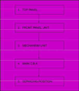
3.1.1. DISASSEMBLY FLOW CHART
This flow chart indicates disassembly steps of the cabinet parts and the circuit boards in order to find the necessary items for servicing.
When reassembling, perform the steps in the reverse order. Fig. D1
3.1.2. DETAIL OF DISASSEMBLY METHOD
1. REMOVAL OF THE TOP PANEL
Remove |
4 Screws (A) |
Fig.D2
http://cxema.ru
2. REMOVAL OF THE FRONT PANEL UNIT
Unlock |
7 Tabs (B) |
Fig. D3
3. REMOVAL OF THE MECHANISM UNIT
Remove |
SHIELD PLATE |
|
(NV-SJ407EE) |
Remove |
Screw (C) |
Remove |
3 Screws (D) |
Remove |
2 Screws (E) |
Note:
1.Keep pressing 2 stoppers on Cassette Holder Plate and Press Cassette Holder Plate to the rear.
2.Remove the Mechanism Unit after bend the Cylinder Shield in the direction of the arrow.
Fig. D4
http://cxema.ru
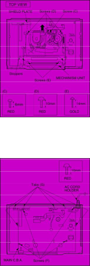
4. REMOVAL OF THE MAIN C.B.A.
Remove |
AC CORD HOLDER |
Remove |
4 Screws (F) |
Unlock |
6 Tabs (G) |
Fig. D5
5. SERVICING POSITION
http://cxema.ru
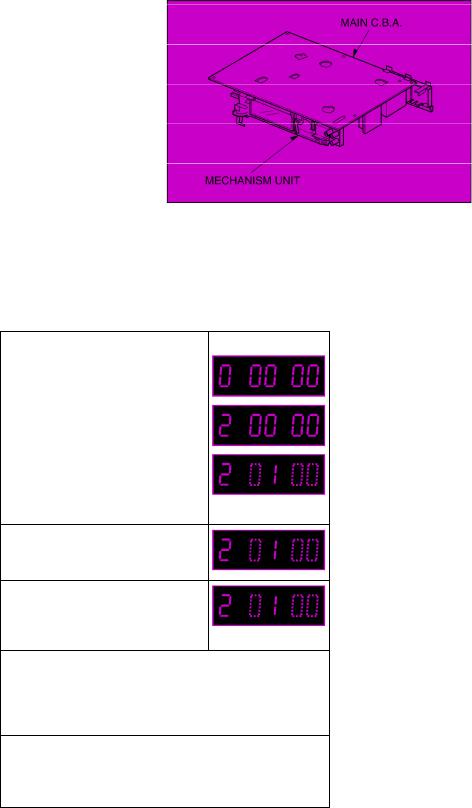
Fig. D6
3.2. MECHANICAL ADJUSTMENT PROCEDURES
Refer to the Service Manual for Z-Mechanism Chassis. / (Order No. VRD9802005C2)
3.3. ELECTRICAL ADJUSTMENT PROCEDURES
3.3.1. PG SHIFTER ADJUSTMENT / (AUTOMATIC)
PROCEDURES |
FIP Display |
Press the FF and EJECT keys |
|
simultaneously for 3 seconds. |
|
|
|
Press the FF and EJECT keys |
|
simultaneously more twice. |
|
|
|
Press the EJECT key for 3 |
|
seconds. |
|
Insert the Alignment Tape. (PAL: VFJ81215H3F) (NTSC: VFM8080HQFP)
This adjustment is automatically started. (During the adjustment, the picture will be appeared on the monitor.)
When this Adjustment is terminated, the following operation will be activated.
-Adjustment completed: The tape will be ejected.
-Adjustment incompleted: "F2*" is indicated on the FIP.Check the Servo/System Control circuit and Cylinder Unit.
To release Service Mode, press the FF and EJECT keys.
simultaneously 6 times until the normal indication on the FIP.
Fig. E1
http://cxema.ru

443NT [L]
A.COMP
A.COMPO
A.D.P [L]
A.D/L [L]
A.DEF [S]
A.DEF [S] [L]
A.DUB P [L]
A.DUB [H]
A.ERASE
A.H. SW
A.HEAD [R]
A.HEAD [W]
A.IN [L]
A.IN [R]
A.MUT [H]
A.MUTE [H]
A.OUT [L]
A.OUT [R]
A.RF OUT A/VS/S. DATA AC ONLINE AC. O/EE. H AFC S C
AFC [S] AFC. DEF ARFC OUT ART. V ART. V. MM
ART. V/H/N
AT. V/H/N ATSW/TEST/NOR/SE AUDIO IN [L]
AUDIO IN [R]
AUDIO OUT [L]
AUDIO OUT [R] AUDIO SELECT [H] AUDIO. L
AUDIO. R
AV CNT
AV CTL
AV CTL/S. CLK AV. C.M. AVCNT/METER. R AVSW/METER. L B MODE. H
B.G.P BACKUP 5V BAND. U.E. BANDVL. D BI/MI [L]
4.43 NTSC L
AUDIO COMPONENT SIGNAL AUDIO COMPONENT SIGNAL AUDIO DUBBING PAUSE L AUDIO DUBBING PAUSE L AUDIO DEFEAT
AUDIO DEFEAT
AUDIO DUBBING PAUSE L AUDIO DUBBING H
AUDIO ERASE
AUDIO HEAD SWITCHING PULSE AUDIO HEAD (REC)
AUDIO HEAD (PLAY) AUDIO INPUT (L) AUDIO INPUT (R) AUDIO MUTE H AUDIO MUTE H AUDIO OUTPUT (L) AUDIO OUTPUT (R)
AUDIO RF SIGNAL OUTPUT AV SW/SERIAL DATA
AC ONLINE
AC ONLINE/EE H AFC S CURVE AFC S CURVE AFC DEFEAT
AUDIO RF SIGNAL OUTPUT ARTIFICIAL VERTICAL SYNC SIGNAL ARTIFICIAL VERTICAL SYNC SIGNAL MONO MULTI ARTIFICIAL VERTICAL SYNC SIGNAL H/NORMAL
ARTIFICIAL VERTICAL SYNC SIGNAL TEST/NORMAL/SERVICE
AUDIO INPUT (L)
AUDIO INPUT (R)
AUDIO OUTPUT (L)
AUDIO OUTPUT (R)
AUDIO SELECT H AUDIO (L)
AUDIO (R) AV CONTROL AV CONTROL
AV CONTROL/SERIAL CLOCK AV CONTROL MODE
AV CONTROL/LEVEL METER (R) AV SW/LEVEL METER (L)
B MODE H
BURST GATE PULSE BACK UP 5V
BAND U
BAND VL BILINGUAL/MIX L
BIL BIL [L] BIL. [H]
BIL/M1 [L]
BS CLOCK
BS DATA
BS LCH IN
BS MIX [H]
BS MON [H] BS MONI [H] BS RCH IN BS VIDEO
BS VIDEO/BS1 BS [H]
BS. LEVEL
BS. M [H]
BS/VTR [H]
BUS CLK
BUS LSN
BUS TLK
BUZZER
CAP EC CAP M GND CAP. ET CAP. FG1 CAP. FG2 CAS. SW CCN
CCP
CHM
CHP CINEM [L] CINEMA [L]
CINEMA/MIX CKL
CKS
CL
CLK
CLK (C.G)
CLOCK. IN CLP COL/B/W/NOR COLOR [H] CONV
CS
CTL GND CTL HEAD [+] CTL HEAD [−] CTL [+]
CTL [−] CUE BIAS
CURRENT LIM CYL ET
BILINGUAL BILINGUAL L BILINGUAL H BILINGUAL L BS CLOCK BS DATA
BS L CHANNEL INPUT BS MIX H
BS MONITOR H
BS MONITOR H
BS R CHANNEL INPUT BS VIDEO SIGNAL
BS VIDEO SIGNAL BS H
BS LEVEL
BS MONITOR H BS/VTR H
BUS CLOCK
BUS LISTEN BUS TALK BUZZER
CAPSTAN TORQUE CONTROL CAPSTAN MOTOR GND CAPSTAN TORQUE CONTROL CAPSTAN FG1 PULSE CAPSTAN FG2 PULSE CASSETTE SW
PLAYBACK CONTROL SIGNAL (−) PLAYBACK CONTROL SIGNAL (+) CONTROL SIGNAL (+)
CONTROL SIGNAL (−) CINEMA L
CINEMA L
CINEMA/MIX
RATCH LOCK
SHIFT LOCK CLOCK CLOCK CLOCK CLOCK INPUT CLAMP
COLOUR/BLACK & WHITE/NORMAL COLOUR H
CONVERTOR
CHIP SELECT
CONTROL GND CONTROL HEAD (+) CONTROL HEAD (−) CONTROL HEAD (+) CONTROL HEAD (−) CUE BIAS CURRENT LIMMITER
CYLINDER TORQUE CONTROL
CYL GND |
CYLINDER GND |
|
FULL. E. 12V |
FULL ERASE 12V |
D.F.M. REC [H] |
DELAIED FM RECORDING H |
|
GND [A] |
GND (ANALOG) |
D. FM REC [L] |
DELAIED FM RECORDING L |
|
GND [TU] |
GND (TUNER) |
D. GND |
DIGITAL GND |
|
GND/N. SW. 12V |
GND/NON SW 12V |
D. REC [H] |
DELAYED RECORDING H |
|
H. SYNC |
HORIZONTAL SYNC |
D4/S. LED |
D4/STILL LED |
|
H. AMP. SW |
HEAD AMP SW PULSE |
D4/STILLED |
D4/STILL LED |
|
H. P <R> |
HEAD PHONE (R) |
DAC [CLK] |
TUNER DAC (CLOCK) |
|
H. P <L> |
HEAD PHONE (L) |
DAC/FSCS |
TUNER DAC/FS CHIP SELECT |
|
H. P GND |
HEAD PHONE GND |
DAREC [H] |
DELAYED AUDIO RECORDING H |
|
H. P OUT [L] |
HEAD PHONE OUTPUT (L) |
DATA |
DATA |
|
H. P OUT [R] |
HEAD PHONE OUTPUT (R) |
DECODER [L] |
DECODER (L) |
|
H. SW |
HEAD SW PULSE |
DECODER [R] |
DECODER (R) |
|
HEAD PHONE [L] |
HEAD PHONE (L) |
DEW |
DEW |
|
HEAD PHONE [R] |
HEAD PHONE (R) |
DEW SNS |
DEW SENSOR |
|
HEAD SW |
HEAD SW |
DFMRE [H] |
DELAYED FM AUDIO RECORDING H |
|
HEATER [+] |
HEATER (+) |
E. REC 5V |
EXCEPT RECORDING 5V |
|
HEATER [−] |
HEATER (−) |
EC |
ERROR TORQUE CONTROL |
|
HSS |
HORIZONTAL SYNC SIGNAL |
ECR |
ERROR TORQUE CONTROL |
|
HTR [+] |
HEATER (+) |
|
REFERENCE VOLTAGE |
|
HTR [−] |
HEATER (−) |
EDT TRIG [L] |
EDIT TRIGGER L |
|
I RFE |
REFERENCE CURRENT |
EDIT [H] |
EDIT H |
|
ICL |
CONTROL AGC CIRCUIT |
EE [H] |
EE H |
|
IF |
INTERMEDIATE FREQUENCY |
EE [H]/INS [M] |
EE H/INSERT M |
|
IN SELA1 |
INPUT SELECT A1 POSITION |
EE. VV. TR |
EE/VV/TRICK PLAY |
|
IN SELA2 |
INPUT SELECT A2 POSITION |
EJECT. PO |
EJECT POSITION |
|
IN SELA3 |
INPUT SELECT A3 POSITION |
EJECT/VDET |
EJECT/REVERSE SLOW LOCK |
|
INS L/R [L] |
INSERT Lch/Rch L |
ENV. SEL |
ENVELOPE SELECT |
|
INS. [H] |
INSERT H |
ENVE. OUT |
ENVELOPE OUTPUT |
|
INSEL A1 |
INPUT SELECT A1 POSITION |
ENVE. SEL |
ENVELOPE SELECT |
|
INSEL A2 |
INPUT SELECT A2 POSITION |
ENV SELECT |
ENVELOPE SELECT |
|
INSERT |
INSERT |
EP [H] |
LP H |
|
INSERT [H] |
INSERT H |
EP/LP [H] |
LP H |
|
IO CS |
INPUT/OUTPUT CHIP SELECT |
EP/LP/SP |
LP/SP |
|
JOG1 |
JOG1 |
EP/SS [H] |
LP/SLOW/STILL/STOP H |
|
JOG S3 LED/FOWRD |
JOG LED/FORWARD LED |
EPROMCS |
EPROM CHIP SELECT |
|
JOG/F. LED |
JOG LED/FORWARD LED |
EX. REC 5V |
EXCEPT RECORDING 5V |
|
JSB [H] |
JSB H |
FF/REW [L] |
FIRST FORWARD/REWIND L |
|
JST. CLCK |
JUST CLOCK |
FG1 IN |
FG1 PULSE INPUT |
|
JST. CLK |
JUST CLOCK |
FG2 IN |
FG2 PULSE INPUT |
|
JST. CLOCK |
JUST CLOCK |
FILTER ADJUSTMENT |
FILTER ADJUSTMENT |
|
L. OUT |
Lch OUTPUT |
FLY ERASE [H] |
FLYING ERASE HEAD ON H |
|
L. CH [H] |
Lch H |
FLY ON [H] |
FLYING ERASE HEAD ON H |
|
L. CH [L] |
Lch L |
FLY. E [H] |
FLYING ERASE HEAD ON H |
|
LED (MAIN) |
LED (MAIN) |
FM MUT [H] |
FM AUDIO MUTE H |
|
LED (STEREO) |
LED (STEREO) |
FM MUTE [H] |
FM AUDIO MUTE H |
|
LED (SUB) |
LED (SUB) |
FM OUT [L] |
FM OUTPUT (L) |
|
LED CKL |
LED SERIAL CLOCK |
FM OUT [R] |
FM OUTPUT (R) |
|
LED CKS |
LED SERIAL CLOCK |
FM PACK OUT [L] |
FM PACK OUTPUT (L) |
|
LED DATA |
LED SERIAL DATA |
FM PACK OUT [R] |
FM PACK OUTPUT (R) |
|
LINE IN 1 [L] |
LINE INPUT 1 (L) |
FM/BS SEL [L] |
FM/BS SELECT (L) |
|
LINE IN 1 [R] |
LINE INPUT 1 (R) |
FM/BS SEL [R] |
FM/BS SELECT (R) |
|
LINE IN 2 [L] |
LINE INPUT 2 (L) |
FS. CLK |
FS CLOCK |
|
LINE IN 2 [R] |
LINE INPUT 2 (R) |
FUL. E [H] |
FULL ERASE HEAD ON H |
|
LINE IN V |
LINE INPUT VIDEO |
FULL. E [H] |
FULL ERASE HEAD ON H |
|
LINE IN [L] |
LINE INPUT (L) |
|
|
|
|
|

LINE IN [R] |
LINE INPUT (R) |
|
P-OFF [H] |
LINE OUT [L] |
LINE OUTPUT (L) |
|
P-OFF [L] |
LINE OUT [R] |
LINE OUTPUT (R) |
|
P. FAIL |
LP [H] |
LP H |
|
P. OFF [H] |
LPTRI [L] |
LP TRICK PLAY L |
|
P. OFF [L] |
Lch/A. DUB |
Lch/AUDIO DUBBING |
|
PAL [H] |
M GND |
MOTOR GND |
|
PAL [L]/NTSC [H] |
M REG |
MOTOR REGULATOR |
|
PB ADJ OUT |
MAIN OUT |
MAIN OUTPUT |
|
PB OUT |
MAIN [L] |
MAIN L |
|
PB. H |
MAIN/MONO |
MAIN/MONAURAL |
|
PFG |
MAX IN |
MAXIMAM INPUT |
|
PHOTSN +B |
MES [H] |
MESECAM H |
|
PICT. CNT |
MESE [H] |
MESECAM H |
|
PLAY LED/RVS LED |
MESE [L] |
MESECAM L |
|
PLAY. PO |
METER 5V |
LEVEL METER 5V |
|
PLAY/R. LED |
METER [L] |
LEVEL METER (L) |
|
PLY/DEW |
METER [R] |
LEVEL METER (R) |
|
POWER OFF [L] |
METER. L/AVS |
LEVEL METER (L) |
|
PREROLL [H] |
METER. R/AVC |
LEVEL METER (R) |
|
PWRFAIL |
MI/BI [L] |
MIX H/BILIGUAL |
|
R. CH [H] |
MIC GND |
MIC GND |
|
R. CH [L] |
MIC IN |
MIC INPUT |
|
R. ST |
MIC IN [L] |
MIC INPUT (L) |
|
R/S/F |
MIC IN [R] |
MIC INPUT (R) |
|
RCH [H] |
MIC [H] |
MIC H |
|
REC 12V |
MIX [H] |
MIX H |
|
REC CHROMA |
MIX [H]/CINEMA [L] |
MIX H/CINEMA SOUND L |
|
REC H |
MIX/CINE |
MIX H/CINEMA SOUND L |
|
REC IN |
MIX/CINEMA [L] |
MIX H/CINEMA SOUND L |
|
REC OUT [L] |
MN. H/M. L |
MONAURAL H/MAIN L |
|
REC START |
MN. H/MAI. L |
MONAURAL H/MAIN L |
|
REC VR [C] |
MN2/MES. L |
MONAURAL 2/MESECAM L |
|
REC VR [L] |
MODE SEL |
AUDIO MODE SELECT |
|
REC VR [R] |
MODE SW |
AUDIO MODE SW |
|
REC Y |
MODE. S. IN |
AUDIO MODE SELECT INPUT |
|
REC [H] |
MODE. S. OUT |
AUDIO MODE SELECT OUTPUT |
|
REC. C |
MONO [H] |
MONAURAL H |
|
REC. Y |
MONO [H]/MAIN [L] |
MONAURAL H/MAIN L |
|
REC/EE CTL |
MONO2 [L] |
MONAURAL 2 |
|
REEL-T |
MONO2/MESE [FM(L)] |
MONAURAL 2/MESECAM (FM L) |
|
REEL-S |
MOTOR GND |
MOTOR GND |
|
REGULATOR FILTER |
MUTE |
MUTE |
|
RESET |
N. A. REC [L] |
NORMAL AUDIO RECORDING |
|
REV M F/R |
N. SW 12V |
NON SW 12V |
|
|
N. SW. 5. DET |
NON SW 5V DETECT |
|
REV M V1 |
NICAM |
NICAM |
|
REV M V2 |
NICAM [L] |
NICAM L |
|
REV MOTOR F/R |
NOL [H] |
PAL H/4.43 NTSC M/3.58 NTSC L |
|
|
NOR/SOFT [H] |
NORMAL/SOFT TAPE PLAY H |
|
REV MOTOR V1 |
NORMAL [H] |
NORMAL H |
|
REV MOTOR V2 |
NR BIAS |
NR BIAS |
|
REV MOTOR [+] |
NTSC [L] |
NTSC L |
|
REV MOTOR [−] |
OCH |
CONTROL AGC CIRCUIT |
|
REV. M. GND |
OUT |
OUTPUT |
|
RF. CHROMA |
|
|
|
|
POWER OFF H
POWER OFF L
POWER FAILURE DETECT POWER OFF H
POWER OFF L PAL H
PAL L/NTSC H
PLAYBACK ADJUST OUTPUT PLAYBACK OUTPUT PLAYBACK H
PG/FG
PHOTO SENSOR +B
PICTURE CONTROL PLAY LED/REVERSE LED PLAY POSITION
PLAY LED/REVERSE LED PLAY/DEW H
POWER OFF L PREROLL H
POWER FAILURE DETECT Rch H
Rch L
RESET
REVERSE H/STOP M/FORWARD L Rch H
RECORDING 12V
RECORDING CHROMINANCE SIGNAL RECORDING H
RECORDING INPUT RECORDING OUTPUT L RECORDING START RECORDING VOLUME (COMMON) RECORDING VOLUME (L) RECORDING VOLUME (R) RECORDING LUMINANCE SIGNAL RECORDING H
RECORDING CHROMINANCE SIGNAL RECORDING LUMINANCE SIGNAL RECORDING/EE CONTROL REEL PULSE (TAKE-UP)
REEL PULSE (SUPPLY) REGULATOR FILTER RESET
REVIEW MOTOR FORWARD/REVERSE REVIEW MOTOR V1 REVIEW MOTOR V2 REVIEW MOTOR FORWARD/REVERSE REVIEW MOTOR V1 REVIEW MOTOR V2 REVIEW MOTOR (+) REVIEW MOTOR (+) REVIEW MOTOR GND
RF CHROMINANCE SIGNAL
RF OUT |
RF OUTPUT |
|
SYSCON 5V |
SYSTEM CONTROL 5V |
RF Y |
RF LUMINANCE SIGNAL |
|
SYSTEM |
SYSTEM SW |
RF. Y. IN |
RF LUMINANCE SIGNAL INPUT |
|
T-PHOTO |
TAKE-UP PHOTO TRANSISTOR |
RF. Y. OUT |
RF LUMINANCE SIGNAL OUTPUT |
|
T-RL. PLS |
TAKE-UP REEL PULSE |
ROTAR. SW |
ROTARY SW |
|
T. BUSCLK |
TIMER BUS CLOCK |
ROTARY |
ROTARY SW |
|
T. BUSLSN |
TIMER BUS LISTEN |
RST |
RESET |
|
T. BUSTLK |
TIMER BUS TALK |
RST [L] |
RESET L |
|
T. END [L] |
TAPE END L |
Rch/INST |
Rch/INSERT |
|
T. PHOTO |
TAKE-UP PHOTO TRANSISTOR |
S IN |
SERIAL DATA INPUT |
|
TAPE END [L] |
TAPE END L |
S OUT |
SERIAL DATA OUTPUT |
|
TAPE END [L]/CAM |
TAPE END L/CAMERA PAUSE |
S-PHOTO |
SUPPLY PHOTO TRANSISTOR |
|
TEST |
TEST MODE |
S-RL. PLS |
SUPPLY REEL PULSE |
|
TPZ |
TRAPEZOIDAL WAVE CIRCUIT |
S. CLK |
SERIAL CLOCK |
|
TRIC [L] |
TRIC PLAY L |
S. CLK/AV |
SERIAL CLOCK/AV |
|
TRICK [L] |
TRIC PLAY L |
S. DATA |
SERIAL DATA |
|
TRK. ENV |
AUTO TRACKING ENVELOPE DETECT |
S. DATA/A |
SERIAL DATA |
|
TU. AUDIO |
TUNER AUDIO |
S. PHOTO |
SUPPLY PHOTO TRANSISTOR |
|
TU. GND |
TUNER GND |
S. TAB [L] |
SAFETY TAB SW ON L |
|
TU. V. IN |
TUNER VIDEO SIGNAL INPUT |
S/P/N |
SECAM/PAL/NTSC |
|
TU. VIDEO |
TUNER VIDEO |
SC IN |
SERIAL CLOCK INPUT |
|
TUN NOR IN |
TUNER NORMAL INPUT |
SC OUT |
SERIAL CLOCK OUTPUT |
|
TUN R |
TUNER AUDIO (R) |
SCK SELECT |
SERIAL CLOCK SELECT |
|
TUN. AUDIO IN |
TUNER AUDIO INPUT |
SEL OUT [L] |
SELECT OUTPUT (L) |
|
TUNER 12V |
TUNER 12V |
SEL OUT [R] |
SELECT OUTPUT (R) |
|
TUNER L |
TUNER AUDIO (L) |
SHUTTLE 1 |
SHUTTLE 1 |
|
TUNER V IN |
TUNER VIDEO SIGNAL INPUT |
SIF |
SOUND INTERMEDIATE FREQUENCY |
|
TUNER [L] |
TUNER AUDIO (L) |
SLMUT [H] |
INPUT SELECT MUTE H |
|
TUNER [N] |
TUNER AUDIO (NORMAL) |
SLNID [+] |
SOLENOID (+) |
|
TUNER [R] |
TUNER AUDIO (R) |
SLNID [−] |
SOLENOID (−) |
|
TUNER. 12 |
TUNER 12V |
SLW TR. MM |
SLOW TRACKING MONO MULTI |
|
TUOFF [H] |
TUNER OFF H |
SLW TR. REF |
SLOW TRACKING REFERENCE |
|
TV. AUDIO |
TV AUDIO |
|
VOLTAGE |
|
TV/VTR |
TV/VTR |
SNS. GND |
SENSOR GND |
|
TXTON [L] |
TEXT ON L |
SOFT [H] |
SOFT TAPE PLAY H |
|
U. REG45V |
UNREGULATOR 45V |
SOFT [H]/NORMAL |
SOFT TAPE PLAY H/NORMAL H |
|
UNREG |
UNREGULATOR |
SOLENOID ON [L] |
SOLENOID ON L |
|
UNREG19V |
UNREGULATOR 19V |
SP [H] |
SP H |
|
V. REF |
REFERENCE VOLTAGE |
SP/L/SLP |
SP/LP |
|
V. EE [H] |
VIDEO EE H |
SSS [L] |
SLOW/STILL/STOP |
|
V. EE [L] |
VIDEO EE L |
STEREO LED |
STEREO LED |
|
VCO REF |
REFERENCE OSCILLATER |
STEREO [H] |
STEREO H |
|
VD. IN |
VIDEO SIGNAL INPUT |
STEREO [L] |
STEREO L |
|
VD. OUT |
VIDEO SIGNAL OUTPUT |
STOP. PO |
STOP POSITION |
|
VIDEO EE [L] |
VIDEO EE L |
STOP/5V |
STOP POSITION/5V |
|
VIDEO IN |
VIDEO SIGNAL INPUT |
STOP1/TAPE SEL |
STOP1 POSITION/TAPE SELECT |
|
VIDEO OUT |
VIDEO SIGNAL OUTPUT |
STOP1/PAL:ST |
STOP1 POSITION/PAL |
|
VM |
MOTOR VOLTAGE |
STOP2. PO |
STOP 2 POSITION |
|
VM DOWN [L] |
MOTOR VOLTAGE DOWN L |
STOP2/S-TAB |
STOP 2 POSITION/SAFETY TAB SW |
|
VSS |
VERTICAL SYNC SIGNAL |
STREO [H] |
STEREO H |
|
VTR [H] |
VTR H |
SUB BIAS |
SUB BIAS |
|
VTR. 12V |
VTR 12V |
SUB. SW |
SUB SW |
|
X IN |
OSCILLATOR INPUT |
SVHS CAS [L] |
S-VHS CASSETTE L |
|
X OUT |
OSCILLATOR OUTPUT |
SW. 5. DET |
SW 5V DETECT |
|
|
|
SYNC [L] |
SYNC L |
|
|
|
|
|
|
|
|
Pin No. |
In/Out |
Port Name |
Function |
|
|
|
|
||
1 |
I |
P.FAIL.IN(L) |
Power failure detection input. |
|
|
|
|||
|
|
|
|
|
|
|
|||
2 |
O |
SP(L) |
This port supplies low during SP mode. |
|
|
|
|||
|
|
|
|
|
|
|
|||
3 |
I |
S.REEL.PULSE |
Supply reel pulse input. |
|
|
|
|||
4 |
I |
T.REEL.PULSE |
Take-up reel pulse input. |
|
|
|
|||
5 |
I |
I.R. |
Remote Controller pulse input. |
|
|
|
|||
|
|
|
|
|
|
|
|||
6 |
O |
OSD REC1 |
OSD REC control output. |
|
|
|
|||
7 |
O |
OSD REC1 |
OSD REC control output. |
|
|
|
|||
8 |
O |
FM MUTE(H) |
Hi-Fi audio mute control output. |
|
|
|
|||
|
|
|
|
|
|
|
|
||
9 |
O |
VIDEO EE(H) |
EE:Low |
|
|
|
|
||
VV:High |
|
|
|
|
|||||
|
|
|
|
|
|
|
|||
10 |
O |
FL DRV CS(L) |
FIP driver chip selection. |
|
|
|
|||
|
|
|
|
|
|
||||
11 |
O |
SQ PB(H) |
This port is high during S-VHS playback mode. |
|
|
||||
12 |
O |
VTR(H)/TV(L) |
VTR/TV mode switching control. |
|
|
|
|||
13 |
O |
CH H/L |
Channel switching control. |
|
|
|
|||
|
|
|
|
|
|
|
|||
14 |
O |
IC.CLK |
FIP driver serial clock output. |
|
|
|
|||
15 |
I |
IC.LSN |
FIP driver serial data input. |
|
|
|
|||
16 |
O |
IC.TLK |
FIP driver serial data output. |
|
|
|
|||
|
|
|
|
|
|
|
|||
17 |
O |
IIC.TALK/LSN |
IIC serial data in/output |
|
|
|
|||
18 |
O |
IIC.CLK |
IIC serial clock output |
|
|
|
|||
19 |
I |
N.C. |
Not used |
|
|
|
|
||
|
|
|
|
|
|
|
|||
|
|
|
Capstan torque switching control. |
|
|
|
|||
|
|
|
1. FF/REW Mode |
|
|
|
|
||
20 |
O |
HALF WAVE(H) |
|
Capstan rotation speed is 1300 rpm or more without VHS-C cassette:High |
|||||
|
Capstan rotation speed is less than 1300 rpm without VHS-C cassette:High impedance |
||||||||
|
|
|
|
||||||
|
|
|
|
VHS-C cassette:High imedance |
|
|
|
||
|
|
|
2. Except FF/REW Mode:High impedance |
|
|
||||
|
|
|
|
|
|
|
|||
21 |
O |
CURRENT LIMIT |
Capstan motor current limitter output. |
|
|
|
|||
|
|
|
|
|
|
|
|
|
|
|
|
|
Capstan rotation direction control. |
|
|
|
|||
22 |
O |
CAP R/F |
Reverse : High |
|
|
|
|
||
|
|
|
Forward : Low |
|
|
|
|
||
|
|
|
|
|
|
|
|||
23 |
O |
VIDEO H.SW |
Video head switching signal output. |
|
|
|
|||
24 |
O |
ART V/H/N |
This port supplies artificial vertical sync signal to stabilize the picture in special playback mode. |
||||||
25 |
I |
RESET(L) |
This port is low during reset. |
|
|
|
|||
|
|
|
|
|
|
|
|||
26 |
O |
D.A.REC(H) |
Audio signal recording on/off control. |
|
|
|
|||
27 |
O |
D.REC(H) |
Video signal recording on/off control. |
|
|
|
|||
|
|
|
This port supplies high during a certain time from starting the recording. |
||||||
|
|
|
|
REC MODE |
|
OUTPUT TIMING |
REC MODE |
OUTPUT TIMING |
|
|
|
|
|
|
|
|
|
|
|
28 |
O |
CUR. EMPH(H) |
|
NTSC 2H |
|
6 sec |
PAL 3H |
9 sec |
|
|
|
|
|
NTSC 4H |
|
12 sec |
--- |
--- |
|
|
|
|
|
|
|
|
|
|
|
|
|
|
|
NTSC 6H |
|
18 sec |
PAL 6H |
18 sec |
|
|
|
|
|
|
|
||||
29 |
O |
128Hz |
Oscillator output for main clock adjustment. |
|
|
||||
|
|
|
|
|
|
|
|||
|
|
|
Full erase on/off control. |
|
|
|
|||
30 |
O |
FULL ERASE(L) |
ON:Low |
|
|
|
|
||
|
|
|
OFF:High |
|
|
|
|
||
31 |
O |
BIAS(L) |
Audio signal recording on/off control. |
|
|
|
|||
|
|
|
|
|
|
|
|||
32 |
O |
A H SW |
Audio head switching signal output. |
|
|
|
|||
33 |
O |
CAP ET |
Capstan torque control. |
|
|
|
|||
34 |
O |
CYL ET |
Cylinder torque control. |
|
|
|
|||
|
|
|
|
|
|
|
|
||
35 |
I |
N.C. |
Not used |
|
|
|
|
||
Pin No. |
In/Out |
Port Name |
Function |
|
36 |
- |
VDD |
Digital 5V |
|
37 |
O |
14.32MHz OUT |
Oscillator output. |
|
|
|
|
|
|
38 |
I |
14.32MHz IN |
Oscillator input. |
|
|
|
|
|
|
39 |
- |
GND |
GND |
|
40 |
I |
32KHz IN |
Oscillator input. |
|
|
|
|
|
|
41 |
O |
32KHz OUT |
Oscillator output. |
|
|
|
|
|
|
42 |
I |
CLK SLCT |
Operating mode select. |
|
43 |
O |
MESECAM |
This port supplies high during Superimpose OSD is displayed in MESECAM mode. |
|
44 |
O |
PICTURE MODE1 |
Picture mode control output. |
|
|
|
|
|
|
45 |
I |
V SYNC |
Analogue V-sync input. |
|
46 |
I |
PICTURE MODE2 |
Picture mode control input. |
|
47 |
O |
CV OUT |
Composite video signal output. |
|
|
|
|
|
|
48 |
- |
GND |
GND |
|
49 |
I |
CV IN |
Composite video signal input. |
|
50 |
I |
CV IN2 |
Composite video signal input. |
|
|
|
|
|
|
51 |
- |
+5V |
+5V |
|
52 |
I |
AFCC |
AFC low pass filter output. |
|
53 |
O |
AFCLPF |
AFC low pass filter input. |
|
|
|
|
|
|
54 |
O |
FSC |
4 muliply low pass filter output. |
|
55 |
I |
FSCLPF |
4 muliply low pass filter input. |
|
56 |
O |
SECAM MUTE |
SECAM chroma signal mute control output. |
|
|
|
|
|
|
57 |
O |
SECAM(L) |
This port supplies low during SECAM tape playback. |
|
58 |
O |
CHARA+HEM |
OSD digital data output. |
|
59 |
O |
I/DK/BG/M |
I/M:Low |
|
BG/DK:High Impedance |
||||
|
|
|
||
|
|
|
|
|
60 |
O |
CHARA |
OSD digital data output. |
|
61 |
O |
AVPB(H) |
This port supplies high during OSD MENU mode and VV mode. |
|
|
|
|
|
|
62 |
O |
AUDIO MUTE(H) |
Audio mute control output. |
|
|
|
|
|
|
63 |
O |
PAL 9H(H) |
This port supplies high during recording in EP(9H) mode. |
|
64 |
I |
GND |
GND |
|
|
|
|
|
|
65 |
I |
CYL PFG |
Cylinder PFG input. |
|
|
|
|
|
|
66 |
I |
GND |
GND |
|
67 |
O |
CAP FG OUT |
Capstan FG output. |
|
68 |
I |
CAP FG |
Capstan FG input. |
|
|
|
|
|
|
69 |
O |
OREF |
Op amp output for 1/2 VDD reference. |
|
70 |
I |
IREF |
Op amp input for 1/2 VDD reference. |
|
71 |
- |
GND |
GND |
|
|
|
|
|
|
72 |
I |
CTL AMP REF |
Control amp reference input. |
|
73 |
- |
+5V |
+5V |
|
74 |
I/O |
CTL HEAD(+) |
Control signal (+) in/output. |
|
|
|
|
|
|
75 |
I/O |
CTL HEAD(-) |
Control signal (-) in/output. |
|
76 |
O |
PB CTL OUT |
Control amp output. |
|
77 |
I |
NC |
Not used |
|
|
|
|
|
|
78 |
O |
EX FF/REW(L) |
This port supplies low during except FF and REW modes. |
|
79 |
I |
MODEL CODE1 |
Model code input. |
|
80 |
I |
MODEL CODE2 |
Model code input. |
|
|
|
|
|
|
81 |
I |
NC |
Not used |
|
82 |
O |
LOAD(H) |
This port supplies high during the mechanism is loaded. |
|
83 |
O |
UNLOAD(H) |
This port supplies high during the mechanism is unloaded. |
|
|
|
|
|
|
84 |
I |
DEW SNS |
Dew detection input. |
Pin No. |
In/Out |
Port Name |
Function |
|
|
|
|
|
|
|
||
|
|
|
Normal/Service/Test2/Test mode selection. |
|||||||||
|
|
|
|
INPUT VOLTAGE |
MODE |
|
|
|||||
|
|
|
|
|
|
|
|
|||||
85 |
I |
NORM/SERV/T2/TEST |
|
More than 4.0V |
Normal |
|
|
|||||
|
|
|
|
|
|
|
|
|
|
|||
|
2.5V - 4.0V |
Service |
|
|
||||||||
|
|
|
|
|
|
|||||||
|
|
|
|
|
|
|
|
|||||
|
|
|
|
1.0V - 2.5V |
Test 2 |
|
|
|||||
|
|
|
|
|
|
|
|
|
||||
|
|
|
|
Less than 1.0V |
|
Test |
|
|
||||
|
|
|
|
|
|
|
|
|
|
|
||
|
|
|
|
|||||||||
86 |
I |
T-PHOT |
This port receives less than 2.4V when Take-up photo sensor detects the tape beginning. |
|||||||||
87 |
I |
S-PHOT |
This port receives less than 2.4V when Supply photo sensor detects the tape end. |
|||||||||
88 |
I |
T.S.CURVE |
Tuner S curve input. |
|
|
|
|
|
||||
|
|
|
|
|||||||||
89 |
I |
TRACKING ENVE |
Playback envelope input for auto tracking adjustment. |
|||||||||
|
|
|
Mechanism position detection input. |
|||||||||
90 |
I |
POS SW1 |
|
P.SW 3 |
P.SW 2 |
P.SW 1 |
|
|
Position(Mode) Name |
|
||
|
0 |
|
0 |
|
0 |
|
EJECT |
|
||||
|
|
|
|
|
|
|
|
|||||
|
|
|
|
|
|
|
|
|
|
|
|
|
|
|
|
|
0 |
|
0 |
|
1 |
|
CASSETTE DOWN |
|
|
|
|
|
|
0 |
|
1 |
|
0 |
|
REV,REV SLOW |
|
|
|
|
|
|
|
|
|
|
|
|
|
|
|
91 |
I |
POS SW2 |
|
0 |
|
1 |
|
1 |
|
MID(LOADING/UNLOADING) |
|
|
|
|
|
|
|
|
|
|
|
|
|||
|
1 |
|
0 |
|
0 |
|
PLAY/REC,STILL/PAUSE,CUE,FWD SLOW,STOP3*1 |
|
||||
|
|
|
|
|
|
|
|
|||||
|
|
|
|
1 |
|
0 |
|
1 |
|
STOP |
|
|
|
|
|
|
|
|
|
|
|
|
|
|
|
|
|
|
|
1 |
|
1 |
|
0 |
|
FF/REW |
|
|
|
|
|
|
|
|
|
|
|
|
|
|
|
92 |
I |
POS SW3 |
|
1 |
|
1 |
|
1 |
|
INTERMEDIATE |
|
|
|
(*1) The Pinch Roller is on the Capstan motor shaft. |
|||||||||||
|
|
|
|
|||||||||
|
|
|
|
|||||||||
93 |
I |
S.TAB(L) |
This port receives low while the cassette tape with safety tab is inserted. |
|||||||||
94 |
I |
N.C. |
Not used |
|
|
|
|
|
|
|
||
|
|
|
FIP on/off control during power off. |
|||||||||
95 |
O |
POWER SAVE(H) |
FIP off:High |
|
|
|
|
|
|
|
||
|
|
|
FIP on:Low |
|
|
|
|
|
|
|
||
96 |
O |
POWER OFF(H) |
Power on/off control. |
|
|
|
|
|
||||
|
|
|
|
|
|
|
|
|
|
|
||
97 |
O |
SLOW MODE (H) |
Not Used |
|
|
|
|
|
|
|
||
98 |
O |
ROTARY SW |
Rotary switching signal output. |
|||||||||
|
|
|
Head amp switching signal output. |
|||||||||
|
|
|
1. 4 Head model |
|
|
|
|
|
||||
99 |
O |
H.A.SW |
|
LP/EP:High |
|
|
|
|
|
|
|
|
|
SP:Low |
|
|
|
|
|
|
|
||||
|
|
|
|
|
|
|
|
|
|
|
||
|
|
|
2. 2 Head model |
|
|
|
|
|
||||
|
|
|
|
Low |
|
|
|
|
|
|
|
|
100 |
I |
ENVE SELECT |
This port receives the playback envelope signal level to select the video head in special playback |
|||||||||
mode. |
|
|
|
|
|
|
|
|||||
|
|
|
|
|
|
|
|
|
|
|||
|
|
|
|
|
|
|
|
|
|
|
|
|
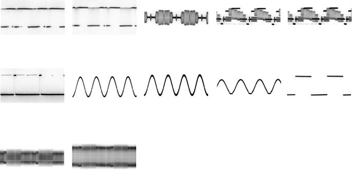
T1150-3 STOP |
T1150-7 STOP |
IC1150-1 STOP |
IC1150-2 STOP |
IC1150-3 STOP |
4.0Vp-p (2msec. div.) |
100Vp-p (5msec. div.) |
2.0Vp-p (10msec. div.) |
15Vp-p (10msec. div.) |
450Vp-p (5msec. div.) |
|
|
|
|
|
IC1150-4 STOP |
IC2501-1,2,16 REC |
IC6001-3,4 FF/REW |
IC6001-14 REC |
IC6001-15,16 REC |
2.0Vp-p (10msec. div.) |
9.0Vp-p (2msec. div.) |
5.0Vp-p (1msec. div.) |
4.8Vp-p (10msec. div.) |
4.8Vp-p (10msec. div.) |
|
|
|
|
|
IC6001-17 REC |
IC6001-18 REC |
IC6001-23 REC |
IC6001-24 PAUSE |
IC6001-38 REC |
4.8Vp-p (10msec. div.) |
4.8Vp-p (10msec. div.) |
5.0Vp-p (10msec. div.) |
4.8Vp-p (10msec. div.) |
3.2Vp-p (50nsec. div.) |
|
|
|
|
|
IC6001-40 REC |
IC6001-47,49 |
IC6001-50 REC/PLAY |
IC6001-65 REC |
IC6001-67 REC |
1.0Vp-p (20msec. div.) |
REC/PLAY |
5.0Vp-p (20msec. div.) |
5.0Vp-p (10msec. div.) |
0.8Vp-p (1msec. div.) |
|
2.0Vp-p (20msec. div.) |
|
|
|
|
|
|
|
|
IC6001-74,75 REC |
IC6001-98 REC |
IC7501-1 STOP |
IC7501-2 STOP |
IC3001-2 REC |
6.0Vp-p (10msec. div.) |
5.0Vp-p (10msec. div.) |
4.8Vp-p (10msec. div.) |
4.8Vp-p (10msec. div.) |
1.5Vp-p (5msec. div.) |
|
|
|
|
|
IC3001-4 PLAY |
IC3001-14 REC |
IC3001-15 PLAY |
IC3001-20 PLAY |
IC3001-24 REC/PLAY |
5.0Vp-p (5msec. div.) |
0.4Vp-p (5msec. div.) |
0.6Vp-p (20msec. div.) |
150mVp-p (20msec. div.) |
5.0Vp-p (10msec. div.) |
|
|
|
|
|
IC3001-37 REC/PLAY |
IC3001-38 REC/PLAY |
IC3001-42,43 PLAY |
IC3001-48 REC |
IC3001-52 REC/PLAY |
4.8Vp-p (10msec. div.) |
4.8Vp-p (10msec. div.) |
0.4Vp-p (20msec. div.) |
1.0Vp-p (20msec. div.) |
2.0Vp-p (20msec. div.) |
|
|
|
|
|
IC3001-56 REC/PLAY |
IC3001-73 REC |
IC3001-78 |
Q4001-C, |
IC3501-1 REC/PLAY |
5.0Vp-p (20msec. div.) |
1.2Vp-p (5msec. div.) |
REC/PLAY |
Q4005-C REC |
5.0Vp-p (10msec. div.) |
|
|
1.2Vp-p (5msec. div.) |
9.0Vp-p (5msec. div.) |
|
|
|
|
|
|
IC3501-30 PLAY |
IC3501-31 REC |
|
|
|
0.4Vp-p (5msec. div.) |
0.3Vp-p (5msec. div.) |
|
|
|
|
|
|
|
|

CAPSTAN |
IC0201 |
|
|
|
|
|
|
|
IC6001 |
|
IC7501 |
(CAPSTAN MOTOR DRIVE) |
|
|
|
|
|
(SYSTEM CONTROL/SERVO IC) |
DP7501 |
||||
MOTOR |
|
|
|
|
|
||||||
L0201 |
|
|
|
|
|
|
|
|
|
|
|
TL0201 |
24 |
MOTOR |
DIFFERENTIAL |
TORQUE |
TL |
|
P0201 |
P2002 |
CURRENT |
|
|
|
22 |
12 |
|
|
|||||||
|
DRIVE |
AMPRIFIER |
CONTROL |
AMP |
|
1 |
21 LIMIT |
|
TIMER DISPLAY |
||
|
25 |
|
|
|
|
|
|
|
|
|
|
|
|
|
|
|
|
|
|
|
EC |
|
P0201 |
P2002 |
|
CAPSTAN |
14.3MHz IN |
38 |
|
|
|
|
|
|
|
|
|
|
|
|
|
|
|
1 |
|
|
10 |
33 |
ERROR |
|
|
F- |
F- |
F+ |
F+ |
|
|
|
|
|
|||
|
|
|
|
|
|
|
|
AMP |
2 |
|
|
|
|
|
|
|
|
||||||||
|
|
|
|
|
|
|
|
|
|
|
|
TORQUE |
|
X6002 |
44 |
45 |
1 |
2 |
39 |
33 |
23 |
5 |
|
||
|
|
|
H3 |
|
|
2 |
|
|
|
|
|
|
|
|
|
||||||||||
|
|
|
|
|
|
|
|
|
|
|
|
|
|
|
|
|
|
|
|
|
|
|
|
||
|
|
|
|
|
|
3 |
POSITION |
|
|
|
|
|
|
CAPSTAN |
14.3MHz OUT |
37 |
|
|
|
|
|
|
|
|
|
|
|
|
|
|
|
4 |
TORQUE |
|
|
P0201 |
P2002 |
|
|
|
|
|
|
|
|
|
|
|
|
||
|
|
|
|
H1 |
|
SIGNAL |
|
7 |
22 |
REVERSE/ |
|
|
|
|
|
|
|
|
|
|
|
||||
|
|
|
|
|
DIRECTION |
|
3 |
|
32KHz IN |
40 |
|
|
|
|
|
|
|
|
|
||||||
|
|
|
|
|
|
|
PROCESS |
|
|
|
|
FORWARD |
|
|
|
|
|
|
|
|
|
||||
|
|
|
|
|
|
5 |
|
|
|
|
|
|
|
|
|
|
|
|
|
|
|
|
|
||
|
|
|
|
|
|
|
|
|
|
REG |
|
|
|
|
|
|
|
|
|
|
|
|
|
|
|
|
|
|
|
|
|
|
|
|
|
26 |
|
|
|
|
X6001 |
|
|
|
|
|
|
|
36 |
SEG1 |
|
|
|
|
|
|
H2 |
6 |
|
|
|
14V |
|
|
|
|
|
|
|
|
|
|
|
||||
|
|
|
|
|
|
|
|
|
|
|
|
|
|
|
|
|
|
|
|
|
|
|
|||
|
|
|
|
|
|
9 |
|
|
|
18 |
|
|
|
|
32KHz OUT |
41 |
|
|
|
|
|
|
|
|
| |
LOADING |
|
|
|
|
|
|
|
|
|
|
|
|
|
|
|
|
|
|
|
|
|||||
|
|
|
|
|
|
|
|
|
|
|
|
|
|
|
|
|
|
|
|
|
|
18 |
SEG18 |
||
MOTOR |
|
|
|
|
|
|
|
|
|
|
|
|
|
|
|
|
|
|
|
|
|
|
|||
|
|
|
|
|
|
|
|
|
|
|
|
|
|
|
|
|
|
|
|
|
|
|
|
||
|
|
P2001 |
|
P2002 |
P0201 |
19 |
|
|
|
15 |
P0201 |
P2002 |
82 |
LOADING H |
|
|
|
|
|
|
|
|
|
|
|
|
|
1 |
|
|
9 |
|
CONTROL |
|
12 |
|
|
|
|
|
|
|
|
|
|
|
|
||||
|
|
|
|
|
|
|
|
|
|
|
|
|
|
|
|
|
|
|
|
|
|
||||
|
|
P2001 |
|
P2002 |
P0201 |
21 |
|
LOGIC |
|
16 |
P0201 |
P2002 |
83 |
UNLOADING |
H |
|
HEATER(-) |
|
|
|
|
|
|
11 |
GRID1 |
|
|
2 |
|
|
8 |
|
|
|
11 |
|
FROM |
Q1001 |
|
|
|
|
|
||||||||
|
|
|
|
|
|
|
|
|
|
|
|
|
|
|
|
|
|
|
|
|
|||||
|
|
|
|
|
|
|
|
|
|
|
|
|
|
|
|
POWER |
HEATER(+) |
|
|
|
|
|
|
|
| |
|
|
|
|
|
|
|
|
|
|
|
|
|
|
|
|
|
|
|
|
|
|
|
|
|
|
|
|
|
|
|
|
|
|
|
|
|
|
|
|
|
|
|
|
|
|
|
|
|
|
17 |
GRID7 |
INPUT |
OUTPUT |
MODE |
|
|
|
|
|
|
|
|
|
|
|
|
|
|
|
|
|
|
|
|
|||
PIN 15 |
PIN 16 |
PIN 19 |
PIN 21 |
|
P0201 |
P2002 |
|
|
|
|
|
CAPSTAN |
|
|
|
|
|
|
|
|
|
|
|
||
|
|
R0206 |
|
|
|
|
68 |
|
|
|
|
|
|
|
|
|
|
|
|||||||
H |
L |
H |
L |
FORWARD |
|
4 |
|
|
|
|
FG IN |
|
|
|
|
|
|
|
|
|
|
|
|||
L |
H |
L |
H |
REWIND |
CAPSTAN |
|
|
|
|
|
|
|
|
|
|
|
|
|
|
|
|
|
|
|
|
FG HEAD |
|
|
|
|
|
|
|
|
|
|
|
|
|
|
|
|
|
|
|
||||||
H |
H |
L |
L |
BRAKE |
|
|
|
|
|
|
|
|
|
|
|
|
|
|
|
|
|
|
|
||
|
|
|
TW2015 |
|
|
|
|
|
|
QR1001 |
|
|
|
|
|
|
|
|
|
||||||
L |
L |
OPEN |
OPEN |
STOP |
|
|
|
|
|
|
|
CAPSTAN |
|
|
|
|
|
|
|
|
|
|
|||
|
|
|
|
|
|
|
67 |
|
|
|
|
|
|
|
|
|
|
|
|||||||
|
|
|
|
|
|
|
CAP FG5V |
|
|
|
|
|
TW2002 |
FG OUT |
P.SAVE H |
45 |
|
|
|
|
|
|
|
|
|
|
|
|
|
|
|
|
|
|
|
|
|
|
|
|
TW1004 |
|
|
|
|
|
|
||||
|
|
|
|
|
|
|
|
|
|
|
|
|
|
|
|
|
|
|
|
|
|
|
|
||
|
|
|
|
|
|
|
|
|
|
|
(SJ407) |
|
|
|
|
|
|
|
|
|
|
|
|
|
|
|
|
|
|
|
|
|
|
|
|
|
|
|
|
|
|
|
|
|
|
|
|
|
|
|
|
|
|
76 |
CTL OUT |
|
|
|
|
|
|
UNREG |
|
QR2001 |
|
|
BACK UP 5V |
36 |
|
|
|
||
|
|
|
|
|
|
5.9V |
||||
|
|
78 |
FF/REW |
L |
|
|
IC6005 |
|
B6001 |
|
|
|
|
|
|
|
UNREG |
||||
|
|
|
|
|
|
|
|
|
5V |
|
|
|
|
|
P.FAIL |
L |
1 |
1 |
RESET |
2 |
|
|
|
|
|
|
|
|
IC6004 |
TL7510 |
TL7509 |
|
S2001 |
1 |
|
|
|
|
|
|
IR |
|
|
2 |
91 |
POSITION SW2 |
IR |
5 |
1 |
3 |
|
|||
MODE |
RECEIVER |
|
||||||||
3 |
90 |
POSITION SW3 |
|
|
|
|
|
|||
SW |
|
|
|
|
|
|
||||
4 |
92 |
POSITION SW1 |
|
|
|
|
|
|
||
|
|
|
|
|
|
|
||||
CYLINDER STATOR UNIT |
|
|
|
RESET |
L |
25 |
|
|
|
|
REG |
IC2501 (CYLINDER MOTOR DRIVE) |
S.DATA IN 15 |
14V |
|
P2901 |
|
|
|
|
|
|
|
|
|
|
|
|
|
|
|
|
|
6,7 |
VM |
P2501-3,4 |
|
|
|
|
|
|
|
S.DATA OUT |
16 |
|
|
|
1 |
SERIAL DATA |
MAIN COIL 2 |
1 |
M2 |
P2501-9 |
2 |
MOTOR |
|
|
|
|
|
|
|
|
|
|
|
|
MAIN COIL 1 |
9 |
M1 |
P2501-1 |
1 |
PG/FG |
4 |
|
65 CYL PFG |
S.CLOCK |
14 |
|
|
|
2 |
SERIAL CLOCK |
||
DRIVE |
|
|
|
|
|||||||||||||
MAIN COIL 3 |
3 |
M3 |
P2501-7 |
16 |
|
|
|
|
|
|
|
|
|
|
|
|
|
|
|
|
|
|
|
|
|
|
|
|
|
|
|||||
|
5 |
GND |
P2501-5 |
|
|
|
|
|
|
|
FIP CS |
10 |
|
|
|
3 |
CS |
|
8 |
HE- |
P2501-2 |
7 |
DIFFERENTIAL |
|
|
|
|
|
|
|
|
|
|
|
|
|
4 |
HE+ |
P2501-6 |
6 |
|
|
|
|
|
|
|
|
|
|
|
||
HALL |
AMPLIFIER |
|
|
|
|
|
|
|
|
|
|
|
|
||||
2 |
VH+ |
P2501-8 |
|
|
|
|
|
|
|
|
|
|
|
|
|
||
IC |
|
|
|
|
|
|
|
|
|
|
|
|
|
|
|||
|
|
|
|
|
|
|
|
|
|
|
|
|
|
|
|
|
|
|
|
|
REG |
|
|
|
|
|
|
CYLINDER |
|
PLAY |
FF |
SEARCH |
CH UP |
REC |
|
|
|
|
5V |
|
|
TORQUE |
|
|
|
|
S7513 |
S7512 |
S7509 |
S7508 |
S7506 |
|
|
|
|
|
|
SCHMIT |
9 |
|
34 ERROR |
|
|
||||||||
|
|
|
|
|
CONTROL |
|
|
|
|
|
|
|
|
||||
|
|
|
|
|
|
|
|
|
TORQUE |
|
|
|
|
|
|
|
|
|
|
|
|
|
|
|
|
|
|
|
|
|
|
|
|
|
|
|
|
|
|
|
|
|
|
|
TL6001 |
|
|
|
|
|
|
|
|
|
|
|
|
|
|
|
|
|
29 |
125Hz |
|
|
|
|
|
5 |
A2 |
|
|
|
|
|
|
|
|
|
|
|
|
|
|
|
|
(SJ407) |
|
|
|
|
|
|
|
|
|
|
86 TAKE-UP PHOTO |
|
|
|
POWER |
A.DUB |
|
||
|
|
|
|
|
|
|
|
|
|
|
|
S7501 |
S7504 |
|
|||
|
|
|
|
|
|
|
|
|
87 SUPPLY PHOTO |
|
|
|
|
||||
|
|
|
|
|
|
|
|
|
|
|
|
|
|
|
|||
|
|
|
|
|
|
|
|
|
93 SAFETY TAB |
L |
|
|
|
|
|
|
|
|
REG |
|
IC6003 |
|
IC6002 |
|
|
|
|
|
|
|
|
|
|
|
|
|
5V |
|
|
|
|
|
|
|
|
|
|
|
|
|
|||
|
|
(T-REEL SENSOR) |
|
(S-REEL SENSOR) |
|
|
UNREG |
|
|
|
|
|
|
|
|
||
|
|
|
|
|
|
|
|
|
|
|
|
(SJ407) |
|
||||
|
|
|
|
|
|
|
|
|
5V |
|
|
|
|
|
|
|
|
|
|
|
|
|
|
|
|
|
|
|
|
|
|
|
|
|
|
|
|
|
1 |
|
2 |
1 |
2 |
REG |
TL6013 |
|
|
|
|
|
|
PAUSE |
|
|
|
|
|
5V |
|
|
|
|
|
|
S7503 |
|
|||||
|
|
|
|
|
|
|
|
|
|
|
|
|
|
|
|
||
|
|
|
4 |
|
3 |
4 |
3 |
|
3 |
S-REEL PULSE |
|
|
|
|
|
|
|
|
|
|
|
|
|
|
|
|
TL6012 |
|
|
|
|
|
|
|
|
|
|
|
|
|
|
|
|
|
|
|
|
|
|
|
|
4 |
A3 |
Q6001 |
D6007 |
Q6002 |
S6001 |
|
|
|
|
|
|
|
|
|
|
|
|
|
|
TAKE UP |
SENSOR |
SUPPLY |
SAFETY |
|
|
|
|
|
4 |
T-REEL PULSE |
|
EJECT |
REW |
STOP |
T.REC |
CH DOWN |
|
PHOTO |
LED |
PHOTO |
TAB SW |
|
|
|
|
|
|
|
|
|
|||||
SENSOR |
|
SENSOR |
|
|
|
|
|
|
|
|
|
S7502 |
S7511 |
S7510 |
S7507 |
S7505 |
|
|
P4001 |
75 |
CTL HEAD(-) |
|
CTL |
5 |
|||
|
|
|||
HEAD |
P4001 |
74 |
CTL HEAD(+) |
|
|
6 |
|||
|
|
|
 Loading...