


CT-32SX12F
Panasonic CT-32SX12F, CT-32SX12UF, CT-32SX12CF, CT-36SX12F, CT-36SX12UF Service Manual
...
ORDER NO. MTNC020721C1
B5
Service Manual
Color Television
Main Manual
(NA9FL)
Panasonic
Models
Chassis
CT-32SX12F AP381
CT-32SX12UF AP381
CT-32SX12CF AP381
CT-36SX12F AP382
CT-36SX12UF AP382
CT-36SX12CF AP382
This Service manual is issued as a service guide for the models of the NA9FL family listed above. Included in this
manual are a set of schematic, block diagrams, functional descriptions, alignment procedures, disassembly
procedures and a complete parts list.
“WARNING! This servicemanual is designed for experiencedrepair techniciansonly and is not designed for use by the general public.
It does not contain warnings or cautions to advise non-technical individuals of potential dangers in attempting to service a product.
Products powered by electricity should be serviced or repaired only by experienced professional technicians. Any attempt to
service or repair the product or products dealt with in this Service Manual by anyone else could result in seriousinjury or death.”
The service technician is requiredtoreadand follow the “Safety Precautions”and“Important Safety Notice” in this main manual.
Copyright2002by Matsushita Electric Corporation of
America. All rights reserved. Unauthorized copying
®
and distribution is a violation of law.
Important safety notice
Special components are used in this television set which are important for safety. These parts are identified on the
schematic diagram by the symbol and printed in BOLD TYPE on the replacement part list. It is essential that
these critical parts are replaced with the manufacturer’s specified replacement part to prevent x-ray radiation,
shock, fire or other hazards. Do not modify the original design without the manufacturer’s permission.
Safety precautions
General guidelines
An isolation transformer should always be used
during the servicing of a receiver whose chassis is not
isolated from AC power line. Use a transformer of
adequate power rating as this protects the technician
from accidents resulting in personal injury from
electrical shocks. It will also protect the receiver from
being damaged by accidental shorting that may occur
during servicing.
When servicing, observe the original lead dress,
especially in the high voltage circuit. Replace all
damaged parts (also parts that show signs of
overheating.)
Always replace protective devices,suchas
fishpaper, isolation resistors and capacitors, and
shields after servicing the receiver. Use only
manufacturer’s recommended rating for fuses, circuits
breakers, etc.
High potentials are present when this receiver is
operating. Operation of the receiver without the rear
cover introduces danger for electrical shock. Servicing
should not be performed by anyone who is not
thoroughly familiar with the necessary precautions
when servicing high-voltage equipment.
Extreme care should be practiced when handling the
picture tube. Rough handling may cause it to implode
due to atmospheric pressure. (14.7 lbs per sq. in.). Do
not nick or scratch the glass or subject it to any undue
pressure. When handling, use safety goggles and
heavy gloves for protection. Discharge the picture
tube by shorting the anode to chassis ground (not to
the cabinet or to other mounting hardware). When
discharging connect cold ground (i.e. dag ground lead)
to the anode with a well insulated wire or use a
grounding probe.
Avoid prolonged exposure at close range to unshielded
areas of the picture tube to prevent exposure to x-ray
radiation.
The test picture tube used for servicing the chassis at
the bench should incorporate safety glass and
magnetic shielding. The safety glass provide shielding
for the tube viewing area against x-ray radiation as well
as implosion. The magnetic shield limits the x-ray
radiation around the bell of the picture tube in addition
to the restricting magnetic effects. When using a
picture tube test jig for service, ensure that the jig is
capable of handling 40kV without causing x-ray
radiation.
Before returning a serviced receiver to the owner,
the service technician must thoroughly test the unit to
ensure that is completely safe to operate. Do not use a
line isolation transformer when testing.
Leakage current cold check
Unplug the AC cord and connect a jumper between the
two plug prongs.
Measure the resistance between the jumpered AC plug
and expose metallic parts such as screwheads,
antenna terminals, control shafts, etc. If the exposed
metallic part has a return path to the chassis, the
reading should be between 240kΩ and 5.2MΩ. If the
exposed metallic part does not have a return path to
the chassis, the reading should be infinite.
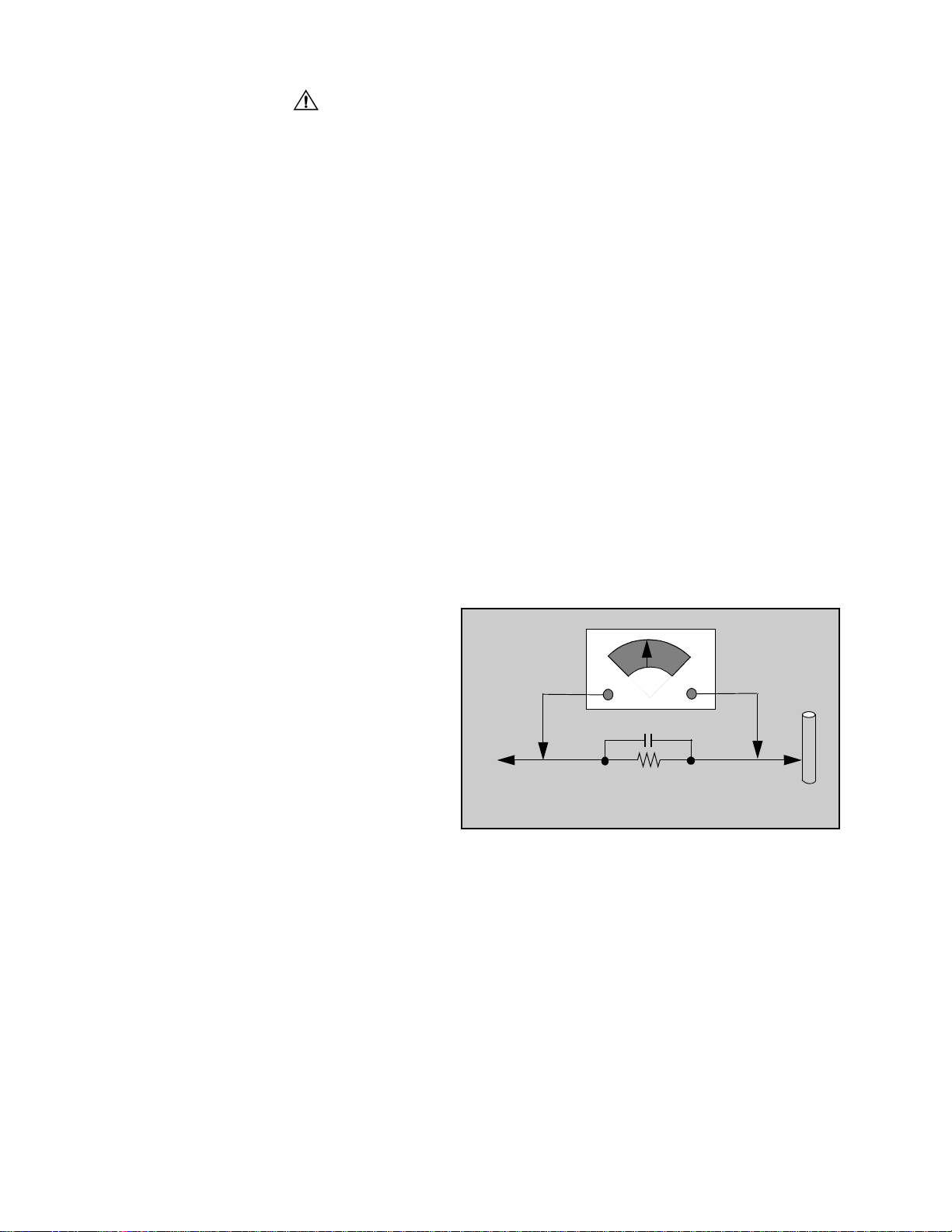
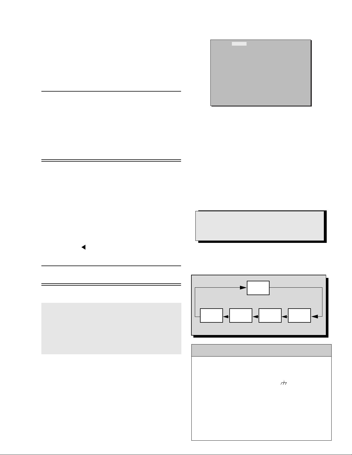
Leakage current hot check (Fig. 1)
Plug the AC cord directly into the AC outlet. Do not use
an isolation transformer during the check.
Connect a 1.5kΩ 10 watt resistor in parallel with a
0.15µF capacitor between an exposed metallic part
and ground. Use earth ground, for example a
water pipe.
Using a DVM with a 1000 ohms/volt sensitivity or
higher, measure the AC potential across the resistor.
Repeat the procedure and measure the voltage
present with all other exposed metallic parts.
Verify that any potential does not exceed 0.75 volt
RMS. A leakage current tester (such a Simpson model
229, Sencore model PR57 or equivalent) may be used
in the above procedure, in which case any current
measure must not exceed 0.5 milliamp. If any
measurement is out of the specified limits, there is a
possibility of a shock hazard and the receiver must be
repaired and rechecked before it is returned to the
customer.
AC VOLTMETER
COLD
WATER
PIPE
(GROUND)
0.15µF
TO INSTRUMENT’S
EXPOSED METAL
PARTS
1500Ω,10 W
Figure 1. Hot check circuit
X-ray radiation
WARNING: The potential source of x-ray radiation in the
TV set is in the high voltage section and the picture tube.
Note: It is important to use an accurate, calibrated
high voltage meter.
Set the brightness, picture, sharpness and color
controls to minimum. Measure the high voltage. The
high voltage should be 31.0 ± 1.0kV. If the upper limit is
out of tolerance, immediate service and correction is
required to insure safe operation and to prevent the
possibility of premature component failure.
Horizontal oscillator disable circuit test
This test must be performed as afinal check before the
Receiver is returned to the customer. See horizontal
oscillator disable circuit procedure check in
this manual.
-2-
About lead free solder (PbF)
component
Note: Lead is listed as (Pb) in the periodic table of elements.
In the information below, Pb will refer to Lead solder, and PbF will refer to Lead Free Solder.
The Lead Free Solder used in our manufacturing process and discussed below is (Sn+Ag+Cu).
That is Tin (Sn), Silver (Ag) and (Cu) although other types are available.
This model uses Pb Free solder in it’s manufacture due to environmental conservation issues. For
service and repair work, we’d suggest the use of Pb free solder as well, although Pb solder may be
used.
PCBs manufactured using lead free solder will have the “PbF” or a leaf symbol stamped on the
back of PCB.
Caution
• Pb free solder has a higher melting point than standard solder. Typically the melting
point is 50 ~ 70 °F(30~40°C) higher. Please use a high temperature soldering iron
and set it to 700 ± 20 °F(370± 10 °C).
• Pb free solder will tend to splash when heated too high (about 1100 °For600°C).
If you must use Pb solder, please completely remove all of the Pb free solder on the
pins or solder area before applying Pb solder. If this is not practical, be sure to heat the
Pb free solder until it melts, before applying Pb solder.
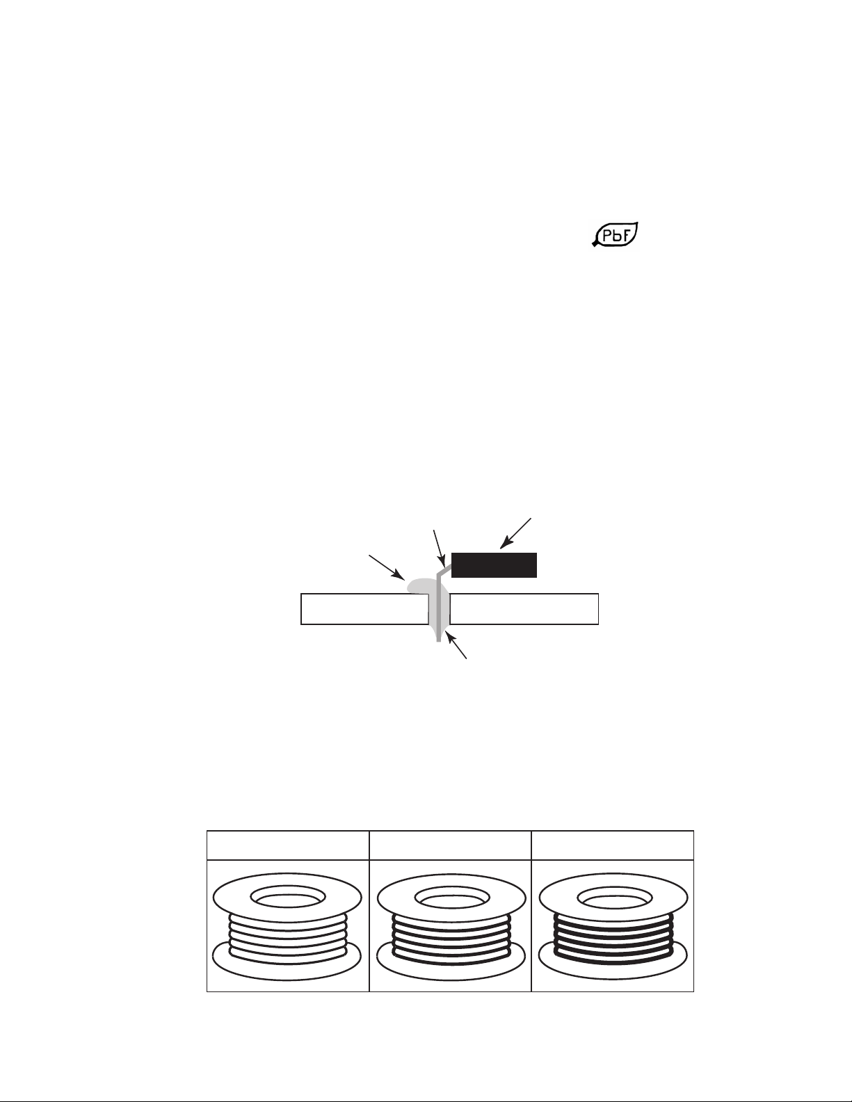
• After applying PbF solder to double layered boards, please check the component side
for excess solder which may flow onto the opposite side. (see figure below)
component
remove all of the
excess solder
pin
slice view
solder
Suggested Pb free solder
There are several kinds of Pb free solder available for purchase. This product uses Sn+Ag+Cu
(tin, silver, copper) solder. However, Sn+Cu (tin, copper), Sn+Zn+Bi (tin, zinc, bismuth) solder
canalsobeused.
0.3mm X 100g
0.6mm X 100g 1.0mm X 100g
-3-
Importantsafetynotice...................2
Safetyprecautions..................2
Generalguidelines..................2
Leakagecurrentcoldcheck...........2
Leakagecurrenthotcheck ...........2
X-rayradiation.....................2
Horizontal oscillator disable circuit test . . 2
Servicenotes ...........................5
Leadless chip component
(surfacemount).................5
Componentremoval ................5
Chip component installation . . ........5
HowtoreplaceFlatIC...............5
Horizontal oscillator disable circuit . . . . . 6
Receiverfeaturetable....................7
Locationofcontrols(receiver).............9
Quick reference control operation . . . . . . 9
Locationofcontrols(remote).............10
Disassemblyforservice .................11
Backcover.......................11
A-Board.........................11
L-Board.........................11
Speakers........................11
Keyboard push button assembly. . . . . . 11
Disassembly for CRT replacement . . . . 11
CRTreplacement .................11
Backcoverremoval.....................13
Chassis service adjustment procedures . . . . 14
140.0V B+ Voltage confirmation . . . . . . 14
Sourcevoltagechart...............14
Highvoltagecheck ................14
Purityandconvergenceprocedure ........15
When the CRT or the yoke is replaced . 15
Verticalrastershiftadjustment .......15
Initial center static convergence . . . . . . 16
Purityadjustment..................16
Finalconvergenceprocedure........16
Dynamic corvergence adjustment . . . . . 16
DY(YHC,YV,XV)adjustment........16
YV Adjustment (VR1 for
Horizontal dynamic convergence). . 16
YH Adjustment (VR2 for
vertical dynamic convergence) . . . . 17
XV Adjustment
(preciseadjustment)............17
Permalloy convergence corrector
strip(partNo.0FMK014ZZ) ......17
DAFadjustment...................17
Servicemode(electroniccontrols).........19
Quickentrytoservicemode.........19
To toggle between aging and
servicemodes.................19
Exitingtheservicemode............19
Tocheckcolors...................19
Entering service mode
(open-back method) . . . . . .......19
Tocheckpurity ...................21
Instructional flow chart for service mode 22
Service adjustments (electronic controls). . . 24
Sub-Contrastadjustment............24
Sub-Brightness(BRIGH)............24
Tint/Coloradjustment ..............24
Tint/Color adjustment
(Norainbowpattern)............25
Color temperature adjustment
(B/WTracking) ................25
Completeadjustment...............25
Horizontalcentering(H-POS)........26
Horizontal width adjustment (H-WIDTH) 26
Horizontal trapezoid
adjustment(HTRAP)............26
Parallelogram adjustment (R524) . . . . . 26
East west PCC balance
adjustment(SIDE)..............26
Vertical linearity adjustment (V-C). . . . . 27
Vertical correction adjustment (V-S) . . .27
Vertical size and vertical position
adjustment(VEAMP&VRAS) ....27
PCCadjustment(PCC).............27
Corner PCC adjustment
(TOPG, TOPSL, BTMG, BTMSL) . .27
MTScircuitadjustments ............28
Inputleveladjustment(MTSIN).......28
Stereo separation adjustment
(SEPAL&SEPAH).............28
Clockadjustment(CLOCK)..........28
Service adjustments
(mechanicalcontrols)...........28
Focus(partofT551)...............28
Audiosignalpathblockdiagram ..........29
Videosignalpathblockdiagram ..........30
Description of connectors. . . . ............31
Component identification . . . . ............33
Partslist ..............................36
Schematics, voltages and waveforms
A-Boardschematic....................50
A-Boardvoltages.....................54
D-Boardschematic....................56
D-Board voltages . . . . . . . . . ............59
A-Boardwaveforms...................60
G-Boardschematic ...................62
G-L-Boardvoltages...................65
L-Boardschematic....................66
A-Boardpcb.........................68
D-Boardpcb.........................70
G-Boardpcb.........................72
L-Boardpcb.........................74
-4-
Service notes
Note: These components are affixed with glue. Be careful not to break or damage any foil under the
component or at the pins of the ICs when removing. Usually applying heat to the component for a
short time while twisting with tweezers will break the component loose.
Leadless chip component
(surface mount)
Chip components must be replaced with identical chips
due to critical foil track spacing. There are no holes in
the board to mount standard transistors or diodes.
Some chips capacitor or resistor board solder pads
may have holes through the board, however the hole
diameter limits standard resistor replacement to 1/8
watt. Standard capacitor may also be limited for the
same reason. It is recommended that identical
components be used.
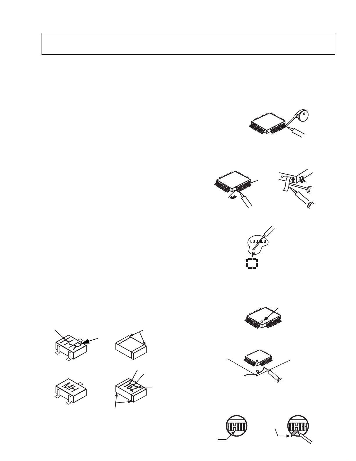
Chip resistor have a three digit numerical resistance
code - 1st and 2nd significant digits and a multiplier.
Example: 162 = 1600 or 1.6kΩ resistor, 0 = 0Ω (jumper).
Chip capacitors generally do not have the value
indicated on the capacitor. The color of the component
indicates the general range of the capacitance.
Chip transistors are identified by a two letter code. The
first letter indicates the type and the second letter, the
grade of transistor.
Chip diodes have a two letter identification code as per
the code chart and are a dual diode pack with either
common anode or common cathode. Check the parts
list for correct diode number.
Component removal
1. Use solder wick to remove solder from component
end caps or terminal.
2. Without pulling up, carefully twist the component
with tweezers to break the adhesive.
3. Do not reuse removed leadless or chip
components since they are subject to stress
fracture during removal.
Chip component installation
1. Put a small amount of solder on the board
soldering pads.
2. Hold the chip component against the soldering
pads with tweezers or with a miniature alligator clip
and apply heat to the pad area with a 30 watt iron
until solder flows. Do not apply heat for more than
3 seconds.
TYPE
Chip components
GRADE
c
SOLDER
CAPS
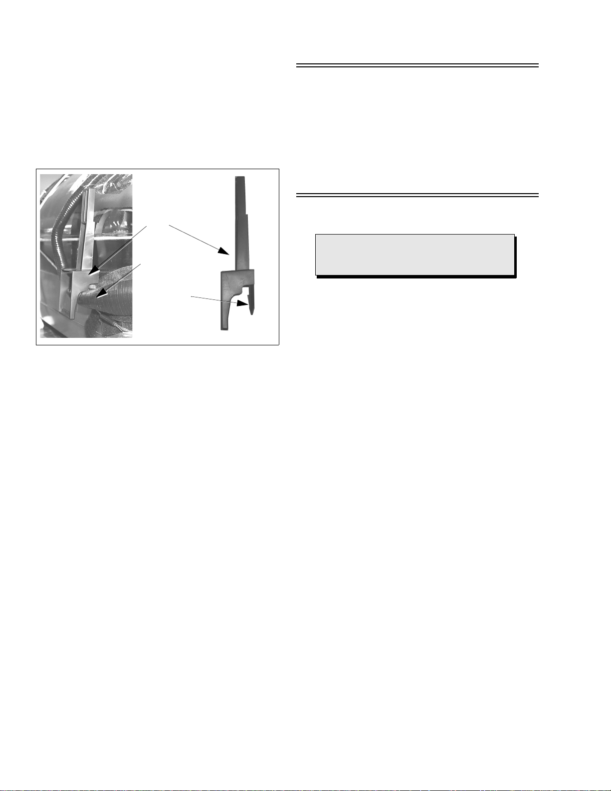
How to replace Flat-IC
- Required Tools -
• Soldering iron • De-solder braids
• Iron wire or small awl • Magnifier
1. Remove the solder from all of the pins of a Flat-IC
by using a de-solder braid.
De-Solder
Flat-IC
2. Put the iron wire under the pins of the Flat-IC and
pull it in the direction indicated while heating the
pins using a soldering iron. A small awl can be
used instead of the iron wire.
Iron
wire
Pull
Soldering
iron
Soldering
iron
3. Remove the solder from all the pads of the Flat-IC
by using a de-solder braid.
Soldering
iron
De-Solder
braid
Flat IC
4. Position the new Flat-IC in place (apply the pins of
the Flat-IC to the soldering pads where the pins
need to be soldered). Properly determine the
positions of the soldering pads and pins by
correctly aligning the polarity symbol.
Polarity symbol
123.....
5. Solder all pins to the soldering pads using a fine
tipped soldering iron.
braid
Awl
b
ANODES
MH DIODE
e
TRANSISTOR
COMMON
CATHODE
SOLDER
CAPS
CAPACITOR
1ST DIGIT
RESISTOR
2ND DIGIT
MULTIPLIER
=1600 = 1.6k
Solder
Soldering
iron
6. Check with a magnifier for solder bridge between
the pins or for dry joint between pins and soldering
pads. To remove a solder bridge, use a de-solder
braid as shown in the figure below.
De-Solder
braid
Solder
bridge
Soldering
iron
-5-

Service notes (continued)
IMPORTANT: To protect against possible damage to
the solid state devices due to arcing or static discharge,
make certain that all ground wires are securely
connected.
CAUTION: The power supply circuit is above earth
ground and the chassis cannot be polarized. Use an
isolation transformer when servicing the receiver to
avoid damage to the test equipment or to the chassis.
Connect the test equipment to the proper ground ( ) or
( ) when servicing, or incorrect voltages will be
measured.
WARNING: This receiver has been designed to meet
or exceed applicable safety and x-ray radiation
protection as specified by government agencies and
independent testing laboratories.
To maintain original product safety design standards
relative to x-ray radiation and shock and fire hazard,
parts indicated with the symbol on the schematic
must be replaced with identical parts. Order parts from
the manufacturer’s parts center using the parts
numbers shown in this service manual, or provide the
chassis number and the part reference number.
For optimum performance and reliability, all other parts
should be replaced with components of identical
specification.
Horizontal oscillator disable circuit
This chassis employs a special circuit to protect
against excessive high voltage and beam current. If, for
any reason, the high voltage and beam current exceed
a predetermined level this protective circuit activates
and detunes the horizontal oscillator that limits the high
voltage. The over-voltage protection circuit is not
adjustable. However, if components indicated by the
symbol on the schematic in either the horizontal
sweep system or the over-voltage protection circuit
itself are changed, the operation of the circuit should be
checked using the following procedure:
Preparation
1. Connect receiver to AC 120 Volts. Do not turn ON.
2. Connect HIGH VOLTAGE meter to 2nd anode
(H.V. button).
Note: Use cold ground( ) for negative lead.
3. Connect the ammeter serial from the flyback anode
lead to the picture tube anode socket.
4. Prepare HHS jig to be connected between TPD50
and TPD51 as shown in Fig. 2.
Procedure
1. Open connector A17.
2. Turn power ON and apply a white pattern.
3. Set current within 50-100µΑ
picture and bright controls.
4. Turn power OFF.
5. Connect HHS jig between TPD50 and TPD51 (VR
should be turn fully clockwise).
6. Turn power on.
7. Turn slowly the variable resistor to increase the
current until the horizontal sync frequency abruptly
increases indicating that the horizontal frequency is
just beginning to pull out of sync. Maintain the
current within
and bright controls
8. Observe the high voltage meter. HIGH VOLTAGE
should read less than 36kV.
9. Turn power OFF, remove HHS jig, HV meter,
ammeter and connect A17 connector.
10. Turn power ON. Reset PICTURE and
BRIGHTNESS controls. Confirm B+ 140V±1.5V
with 120V AC applied.
:
by changing the
50-100µΑ by changing the picture
Note: If high voltage is not within the specified
limit, the cause must be determined before
the receiver is returned to the owner.
Equipment needed to check the disabled circuit:
1. DC ammeter
2. High voltage meter (0- 50kV electrostatic)
3. Variac or isolation transformer
4. HHS jig (see Fig. 2)
TPD50
100Ω
Figure 2. HHS jig
1KΩ
TPD51
-6-
Receiver feature table
FEATURE\MODEL CT-32SX12F/UF/CF CT-36SX12F/UF/CF
Chassis NA9FL
Number of channels 181
Menu language Eng/Span/Fr
Closed Caption X
V-Chip (USA/CANADA) X
Remote model number EUR7613Z10
Picture tube MDDA
Comb filter ADV 3 DIG (NEW)
VM X(DIGITAL)
V/A norm (X=BOTH) X
Color temp X
Preset/input labeling X
Video picture memory X
MTS/SAP/DBX X
BASS/BL/TRE control X
AI Sound X
Surround X
SPATIALIZER/BBE BBE
Built-in audio power 10W X 2
Number of speakers 2
A/V in (rear/front) 3(2/1)
S-VHS input (rear/front) 1/1
Component input
(Y,Pb,Pr)
Audio Out
(FAO: F, VAO: V)
EPJ/HPJ/MISC HPJ
Dimensions mm
(WxDxH) in
Weight (kg/lbs) 72.5/159.83 98.5/217.15
Power source (V/Hz) 120/60
Anode voltage 31.0kV ± 1.0kV
Video input jack
Audio input jack 500mV RMS 47kΩ
894x685x809
35.19x26.96x31.85
1V
p-p
1
F,V
1049.5x742x895
41.32x29.21x35.23
75Ω,phono jack
Specifications
are subject to
change without
notice or
obligation.
Dimensions and
weights are
approximate.
Table 1. Receiver features
-7-

Board description table
BOARD CT-32SX12F/UF/CF CT-36SX12F/UF/CF Description
A-Board TNP2AH037 AC AA MAIN CHASSIS
G-Board TNP2AA113
L-Board TNPA1673 AC CRT BOARD
D-Board TNP2AH041 AB NIL POWER SUPPLY
*Note:
When ordering a replacement board assembly,
NIL KEY BOARD,
FRONT A/V
append an “S” to the board number.
Example: To order the A-Board for CT-27SX12MF, the
replacement board is TNP2AH025AFS.
-8-
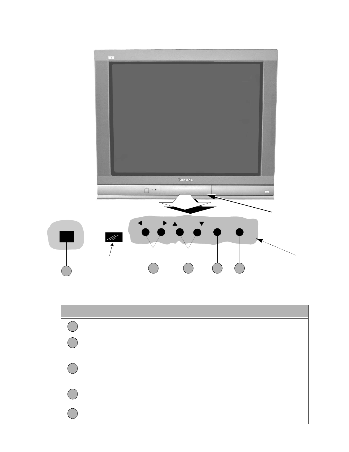
Location of controls (receiver)
POWER
1
Remote control
sensor
VOLUME
2 4 53
CHANNEL ACTION TV/VIDEO
Figure 3. Location of controls (receiver).
Quick reference control operation
1
Power button - Press to turn ON or OFF.
Volume buttons - Press to adjust sound level, or to adjust audio menus, video menus,
2
and select operating features when menus are displayed
Channel buttons - Press to select programmed channels. Press to highlight desired
features when menus are displayed. Also use to select cable converter box channels
3
after programming remote control infra-red codes (the TV/AUX/CABLE switch must be
set in CABLE position).
Front A/V jacks
Controls inside
front door
Action button - Press to display main menu and access on screen feature and
4
adjustment menus.
5
TV/Video button - Press to select TV or video input.
-9-
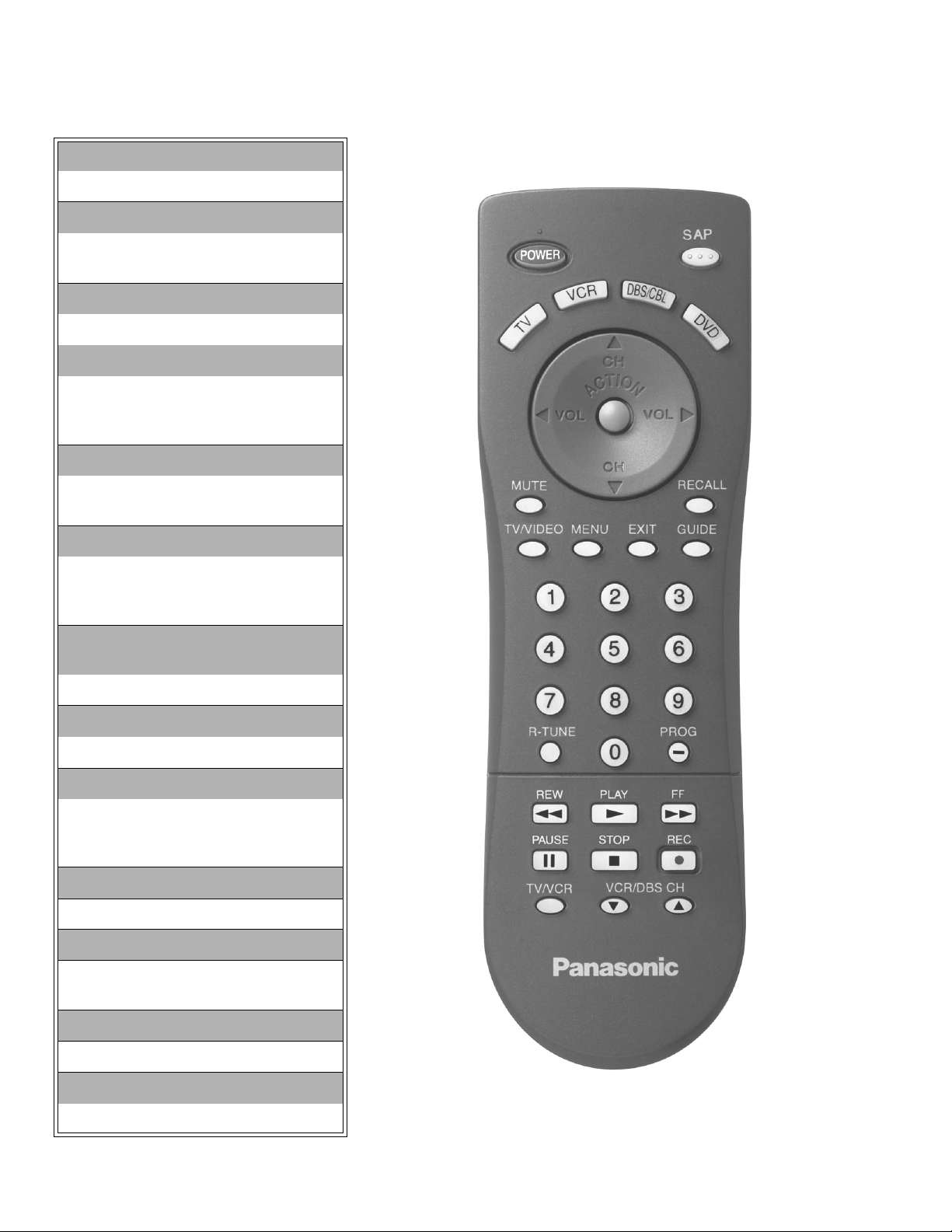
Location of controls (remote)
POWER button
Press to turn ON and OFF.
MUTE button
Press to mute sound.
A second press resumes sound.
TV, VCR, DBS/CBL, DVD
Press to select remote operation
VOL (volume) buttons
Press to adjust TV sound level.
Use with channel buttons to
navigate in menus.
R-TUNE (Rapid Tune) button.
Press to switch to the previous
channel.
ACTION button
Press to display main menu and
access or exit on screen features
and adjustment menus.
REW, PLAY, FF, TV/VCR, STOP ,
PAUSE, REC, VCR/DBS CHANNEL
Component function buttons.
TV/VIDEO button
Press to select TV or Video input.
CH (channel) buttons
Press to select channels.
Use with volume buttons to
navigate in menus.
GUIDE, EXIT buttons
DBS functions button
RECALL button
Press to display time, channel, sleep
timer and other options
SAP button
Press to access second audio program
MENU button
Press to access DBS or DVD menus
Figure 4. Location of controls (remote).
EUR7613Z10
-10-
Disassembly for service
Back cover
Remove all the screws marked with an arrow( )
from the back of the receiver.
Note: Screw configuration, type, and number
of screws vary depending on the
model of the receiver serviced and the
application; various models are
covered in this manual. Use same
hardware when reassembling the
receiver.
• 4 screws at the top edge of the receiver.
• 3 screw by the A/V jacks.
• 1 screw at each lower corner of the receiver.
• 1 screw by the retainer plate of the AC power cord.
A-Board - Main chassis
The A-Board assembly rest on a chassis tray along
with the D-Board. Slide chassis tray out. Gently lift tray
and pull out. Disconnect plug connectors; release wire
ties and holders as required for complete chassis
removal.
1. A & D-Boards are secured to the chassis tray with
screws.
2. The A-Board is mated to the D-Board by three
flexible connectors: A5, A6 & A7 (D5, D6 & D7 on
the D-Board, respectively), A1, A 2 & A3 (G1, G2 &
G3 on the G-Board, respectively), D40 to G40. To
remove either boards, unplug the connectors on
the A-Board.
Note: Some tie-wraps that secure the wire dressings
may need to be unfastened for chassis
removal.
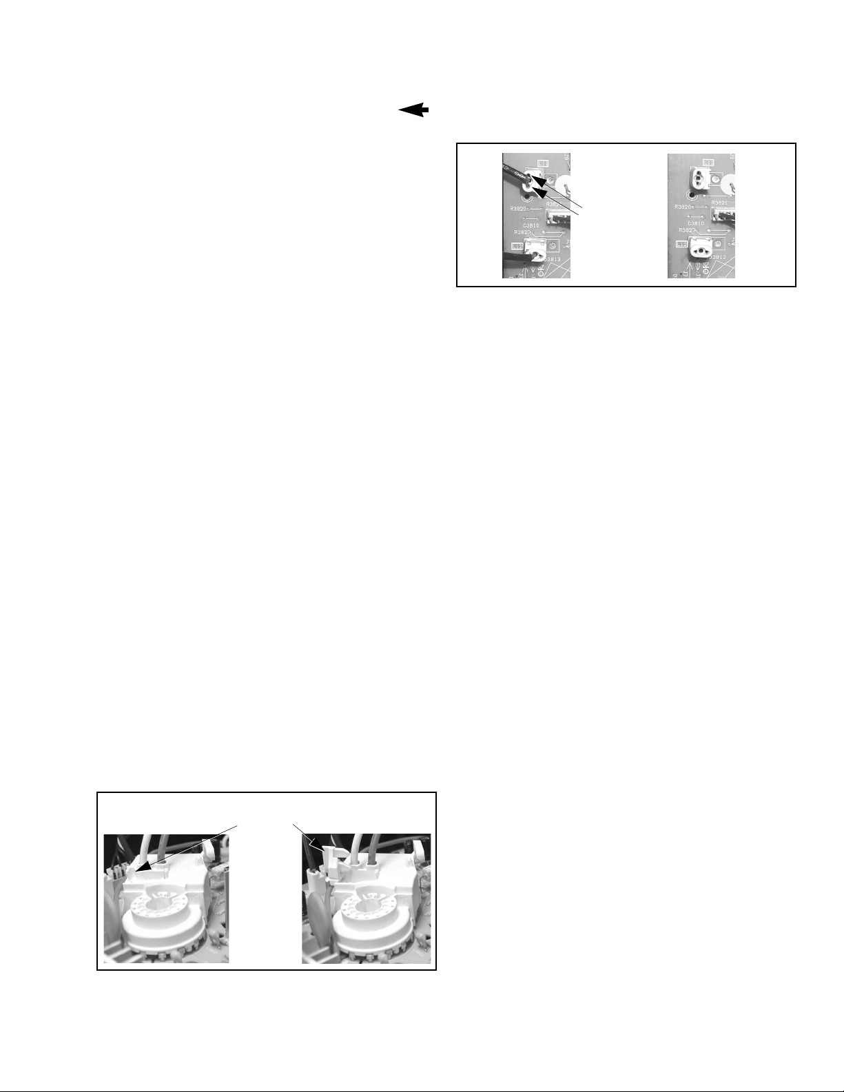
L-Board - CRT output
Plugs into the socket on the CRT neck.
To remove this board, first unplug the board from
the CRT neck, then disconnect L1, L2 & L3
connectors, to disconnect the focus F1 (red cable)
& F2 (white cable) cables, pull the tab and release
the cables, finally disconnect the screen cable from
the D-Board fly-back.
To reinsert back the cables, remember the original
position of cables, F1 (red cable) goes to A on the
CRT socket and F2 (white cable) goes to B on the
CRT socket.
Press tab
leftward to
release cables
Pull cables
upwards
To release screenGND cables from L-Board L11& L12
connectors, insert a wire in both sides of connector and
pull upwards the cable, then remove the wire
(see Fig. 6)
Pull
Insert
wire
cable
upwards
Figure 6. L-Board screen GND cables release
Speakers
Speaker is secured to the cabinet’s front with 4
screws.
Keyboard push button assembly
Fastened to the inside of the cabinet front.
Disassembly for CRT replacement
1. Discharge the CRT as instructed in the safety
precautions (see page 2).
2. Disconnect the yoke (DY) plug, degaussing coil
(DEG) plug and the CRT 2nd anode button from
the board.
3. Remove the L-Board from the CRT socket and
unplug the black wires (CRT dag ground) L11 &
L12.
4. Lift the main chassis (A-Board) and all mounted
boards completely out with the CRT Board attached.
CRT replacement
1. Perform disassembly for CRT replacement
procedure.
2. Insure that the CRT H.V. Anode button is
discharged before handling the CRT. Read the
safety precautions (see page 2) on handling the
picture tube.
3. Remove the components from the CRT neck and
place the cabinet face down on a soft pad.
4. Note the original order for the CRT mounting
hardware as they are remove from the CRT
mounting brackets at each corner of the CRT.
5. Remove the CRT with the degaussing coil and the
dag ground braid attached.
Figure 5. F1 & F2 cables release
-11-
Note:
After servicing the receiver, remember
to dress the cables.
Disassembly for service (continued)
Note: To remove the four brackets holding
the degauss coil from the corners of
the CRT, first remove the CRT from
the cabinet, then remove the brackets
by pressing the tab on the bracket and
pull upwards. These brackets are
included in the degauss coil kit, for part
number, please see parts list section
(see Fig. 7).
Degaussing
coil
bracket
Degaussing
coil
Press tab
then pull
upwards
Note: Reuse all the clampers and mounting
brackets from the degaussing coil and
screen, and when remounting the
degaussing coil assure that is not
touching the speakers, this can be
done by placing some tape
(see Fig. 7), this may cause mask
vibration. The mounting brackets and
clampers are not supplied with the
replacements.
Important notice:
When ordering the CRT, please order CRT
and CRT KIT also. Please see parts list
section for part numbers
Figure 7. Brackets removal
6. Note the original locations and mounting of the
degaussing coil and the dag ground assembly to
insure proper reinstallation on the replacement
CRT.
To remove and remount the degaussing coil:
The degaussing coil is held in place by clampers
fastened to the CRT corner ears. These clampers
must be installed onto the replacement CRT prior
to mounting the degaussing coil.
To remove and remount the dag ground braid:
a.Unhook the coil spring from the bottom corners
of the CRT ears.
b.Release the braid loop from the upper corners of
the CRT ears.
7. Mount the dag ground braid on the replacement
CRT. Position the degaussing coil with new ties.
Dress coil as was on the original CRT.
8. Replace the components on CRT neck and
reinstall into cabinet. Verify that all ground wires
and circuit board plugs get connected.
-12-
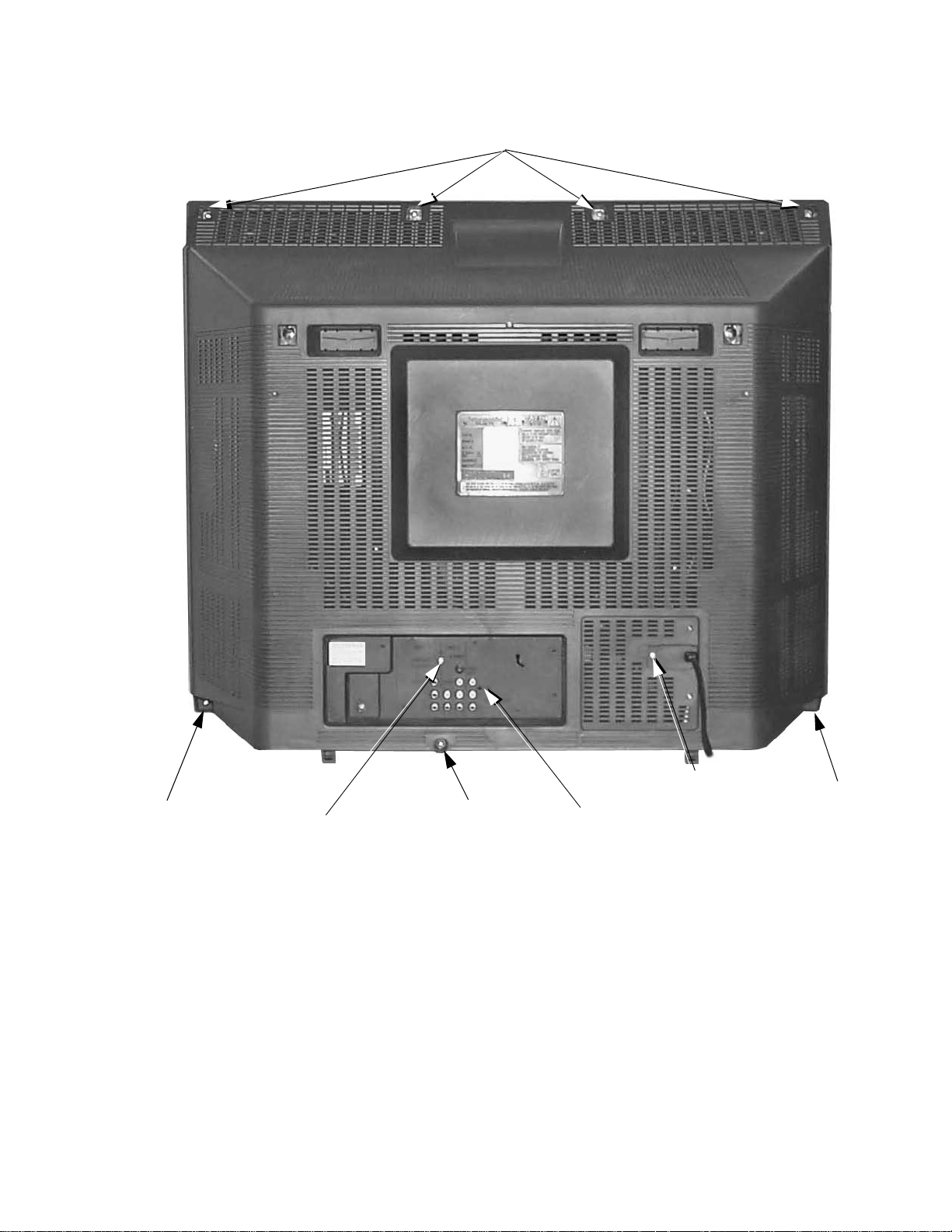
Back cover removal
4 screws at top edge
1 screw at lower
left corner
1 screw
1screw
Figure 8. Back cover removal
-13-
1screw
1screw
1 screw at lower
right corner
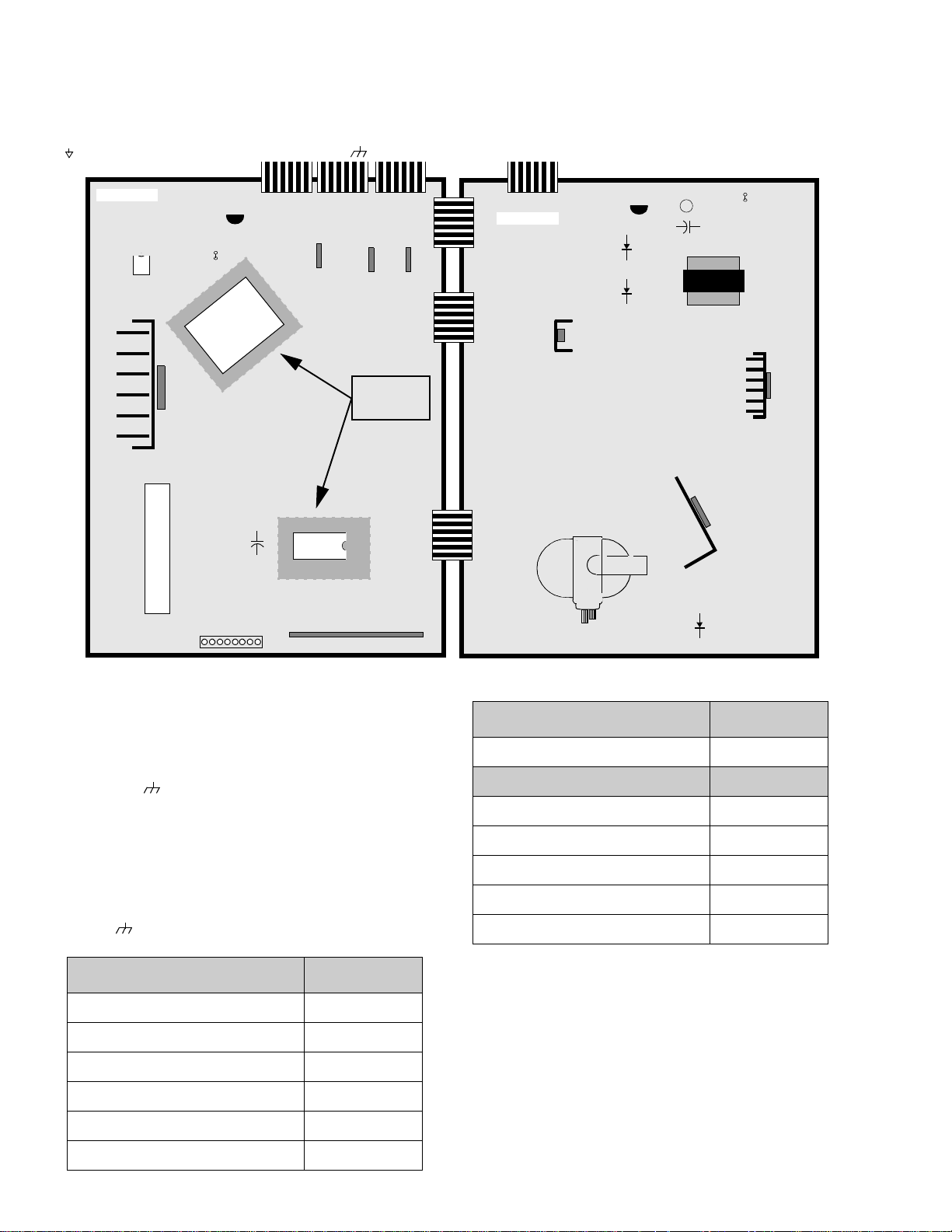
Chassis service adjustment procedures
All service adjustments are factory preset and should not require adjustment unless controls and/or
associated components are replaced.
Note: Connect the (-) lead of the voltmeter to the appropriate ground. Use heat sink when the HOT ground symbol
( ) is used. Otherwise, use COLD ground ( ) — tuner shield.
A-BOARD
IC002
IC2301
T
U
N
E
R
L008
Q002
IC001
C3023
TP
Q804
IC881
-
IC3001
+
A/V REAR INPUTS
18
IC882
IC883
LOCATED
ON BOTTOM
OF BOARD
D-BOARD
Q751
Fly-Back
L826
L824
+
-
D827
C840
D825
T801
Q801
Q551
D511
MOMENTARILY CONNECT A JUMPER FOR ENTERING SERVICE MODE (TP8 to COLD GND)
140.0V B+ Voltage confirmation
1. Set the BRIGHT and the PICTURE to Minimum by
using the picture menu.
2. Connect the DVM between
ground ( ).
3. Confirm that B+ voltage is 140.0V ± 1.5V.This
TPP17 (+ side) and cold
LOCATION (D-Board) VOLTAGE
TPD7
(by D511)
220V 220.0V ± 9.0V
LOCATION (A-Board) VOLTAGE
TP A6
(by IC883)
MAIN12V 12.0V ± 0.5V
voltage supplies B+ to the horizontal output &
flyback circuits.
Source voltage chart
120V AC line input. Set the BRIGHT and the PICTURE
to minimum by using the picture menu. Use cold
ground
(
) for the (-) lead of the DVM.
TP A7
TP A8
TP A16
TP A18
(by IC3001)
(by L008)
(by Q002)
(by C3023)
MAIN 9V 9.0V ± 0.5V
MAIN 5V 5.0V ± 0.3V
STBY 3.3V 3.3V ± 0.2V
BTL30V 32.0V ± 2.0V
.
LOCATION (D-Board) VOLTAGE
TPP17
TPP25
TPP19
(by D825)
(by D827)
(by Q804)
+B2 140.0V ± 1.5V
9V 9.0V ± 1.5V
15V 15.0V ± 2.0V
Adjust Picture menu for normalized video adjustments.
High voltage check
1. Select an active TV channel and confirm that
horizontal is in sync.
2. Adjust BRIGHTNESS and PICTURE using
PICTURE Icon menu so video just disappears.
TPP20
TPP21
(by C840)
(by L826)
15V(VER.) 15.0V ± 1.5V
-15V (VER.) -15.0V ± 1.5V
3. Confirm B+ 140.0V is within limit.
4. Using a high voltage meter confirm that the high
voltage is 31.0kV ± 1.0kV.
TPP22 (
by L824
) SOUND 32.5V ± 2.0V
-14-
Purity and convergence procedure
Adjustment is necessary only if the CRT or the
deflection yoke is replaced or if the setting was
disturbed. The complete procedure consists of:
1. Vertical raster shift adjustment. (Only for models
with purity/convergence assembly with 4 pairs
of rings).
2. Initial static convergence.
3. Setting the purity.
4. Final static convergence.
WhentheCRTortheyokeisreplaced
Place the yoke on the CRT neck (do not tighten
the clamp).
Place the vertical raster shift tabs at 3 o’clock (90ofrom
the purity and convergence tabs)
R&B Convergence Rings
R&B&G Convergence Rings
G3 G4
Vertical Raster Shift Ring
Figure 9. Positioning of purity/convergence assembly
(4 pairs of rings)
Purity Rings Centered
Over G3/G4 Gap
Vertical raster shift adjustment
(only for models with purity/convergence assembly
with 4 pairs of rings).
Apply a green pattern with a horizontal line, adjust the
deflection yoke so that has no tilt, then secure it.
Adjust center line of the pattern with the mechanical
center of the CRT, this center is determined by two
marks at the side edges of the screen. To adjust the
line, once the vertical raster shift tabs are place at 3
o’clock to reduce its magnetic field effect (see Fig. 9
and Fig. 10) open the tabs the same angle from the
center, until the center line of the pattern becomes a
straight line, centered with the marks of the CRT.
(see Fig. 11)
Center line
from pattern
Mechanical
Center Marks
Vertical raster shift tabs
Figure 11. Vertical raster shift adjustment
(4 pairs of rings assembly)
Open the
same angle
from center
R&B&G Convergence rings
R&B Convergence rings
Vertical raster
shift rings
Purity rings
90
o
Figure 10. Positioning of purity/convergence
assembly (4 pairs of rings)
Turn the receiver ON. Operate the receiver for 60
minutes using the first purity check field (white screen)
to stabilize the CRT.
Fully degauss the receiver by using an external
degaussing coil.
Slide the deflection yoke back and forth on the neck of
the CRT until it produces a near white, uniform raster.
-15-
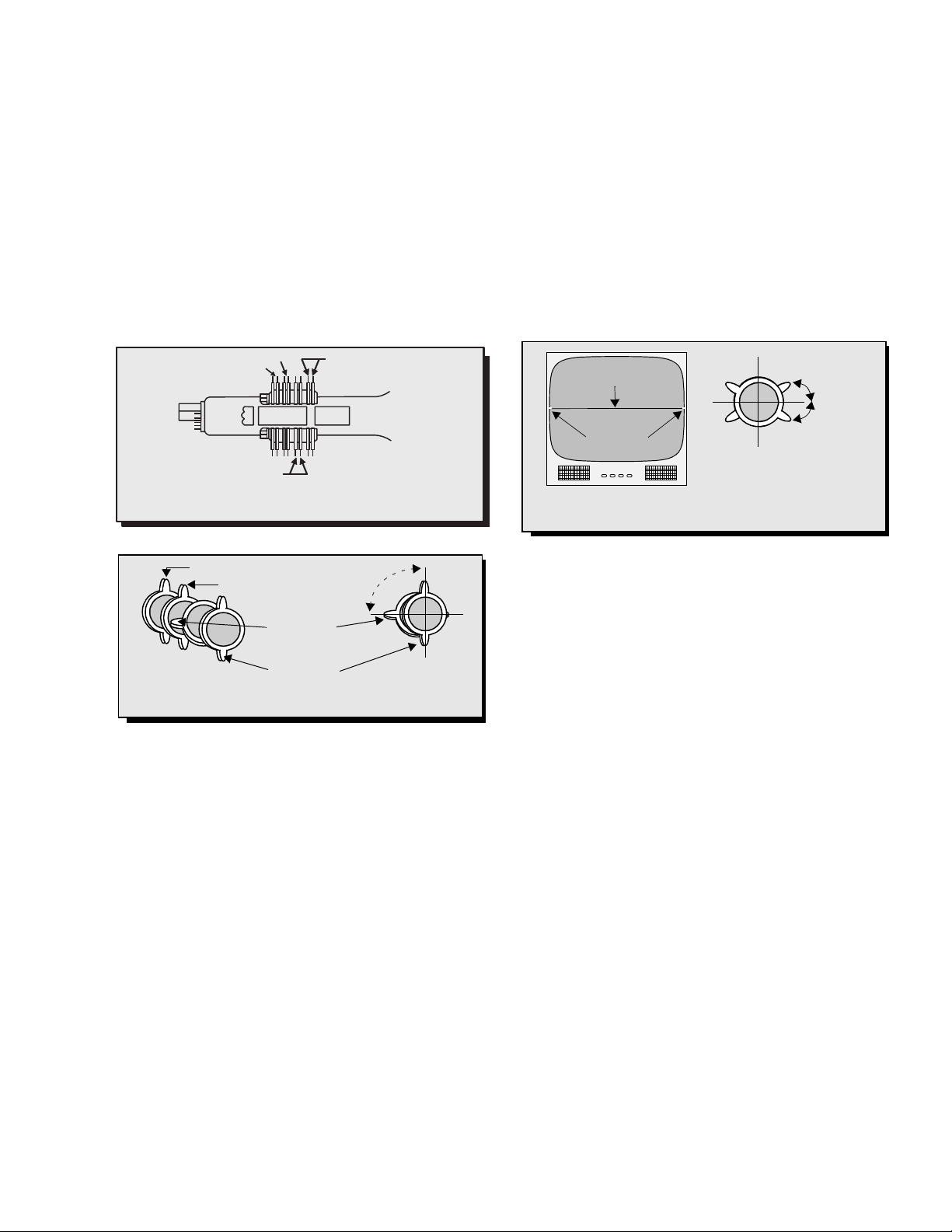
Initial center static convergence
Connect a dot/cross hatch generator to the receiver
and tune in a signal. Observe misconvergence at
center of the screen only.
Adjust the R&B pole magnets; by separating tabs and
rotating to converge blue with red.
Adjust the R&B and R&B&G pole magnets: by
separatingtabsandrotatingtoconvergeblueandred
(magenta) with green.
Note: Precise convergence adjustment at this point
is not important.
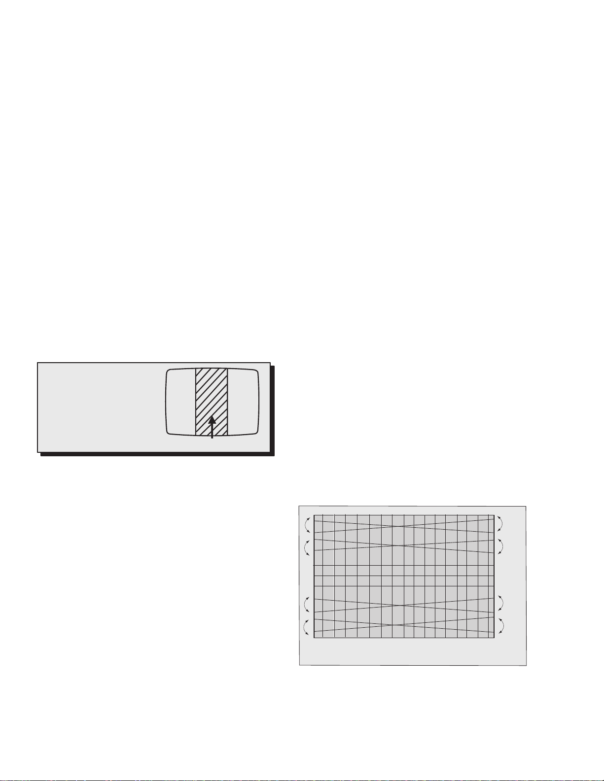
Purity adjustment
When the receiver is in the service mode for making
electronic adjustments, press the RECALL button on
the remote control to enter purity check. (See the
service adjustments electronic controls procedure).
Operate the receiver for 60 minutes using the first
purity check field (white screen) to stabilize the CRT.
Fully degauss the receiver by using an external
degaussing coil.
Press the RECALL button on the remote control again
until the purity check (green screen) appears.
Loosen the deflection yoke clamp screw and move the
deflection yoke back as close to the purity magnet
as possible.
Adjust the purity rings to set the vertical green raster
precisely at the center of the screen (see Fig. 12).
NOTES:
1. CRT warm up with white screen
(three guns activated) is needed
to stabilize the shadow mask
expansion.
2. Initial center static convergence
(roughly centers three gun
beams) is required in order to
performpurityadjustment.
Figure 12. Green raster adjustment
Slowly move the deflection yoke forward until the best
overall green screen is displayed.
Tighten the deflection yoke clamp screw.
Press the RECALL button on the remote control again
until the purity check blue and red screens appear and
observe that good purity is obtained on each respective
field.
Press the RECALL button on the remote control again
until purity check (white screen) appears. Observe the
screen for uniform white. If purity has not been
achieved, repeat the above procedure.
Green raster
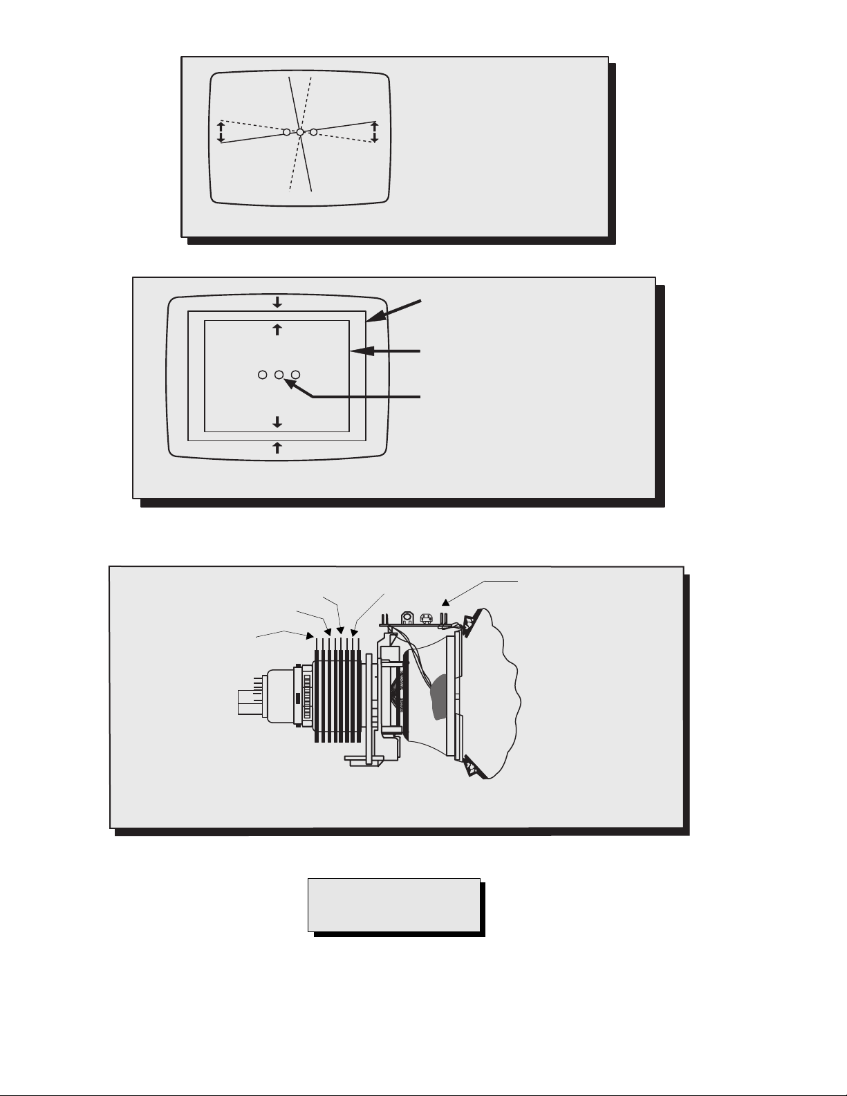
Final convergence procedure
(see Fig. 17 through Fig. 19):
Note: Vertical size and focus adjustments must be
completed prior to performing the convergence
adjustment. Connect a dot pattern generator to the
receiver. The BRIGHTNESS level should not be higher
than necessary to obtain a clear pattern.
Convergethe redand the bluedots at the center of the
screen by rotating the R&B pole static convergence
magnets.
Align The converged red/blue dots with the green dots
at the center of the screen by rotating the R&B&G pole
static convergence magnets. Melt wax with soldering
iron to reseal the magnets.
Slightly tilt vertically and horizontally (do not rotate) the
deflection yoke to obtain a good overall convergence.
If convergence is not reached at the edges, insert
permalloy (see following section) from the DY corners
to achieve proper convergence. Recheck for purity and
readjust if necessary.
After vertical adjustment of the yoke, insert wedge at 11
o’clock position, then make the horizontal
tilt adjustment.
Secure the deflection yoke by inserting two side
wedges at 3 and 7 o’clock positions.
Apply adhesive between tab (thin portion) of wedge
and CRT and place tape over the tab to secure to
the CRT.
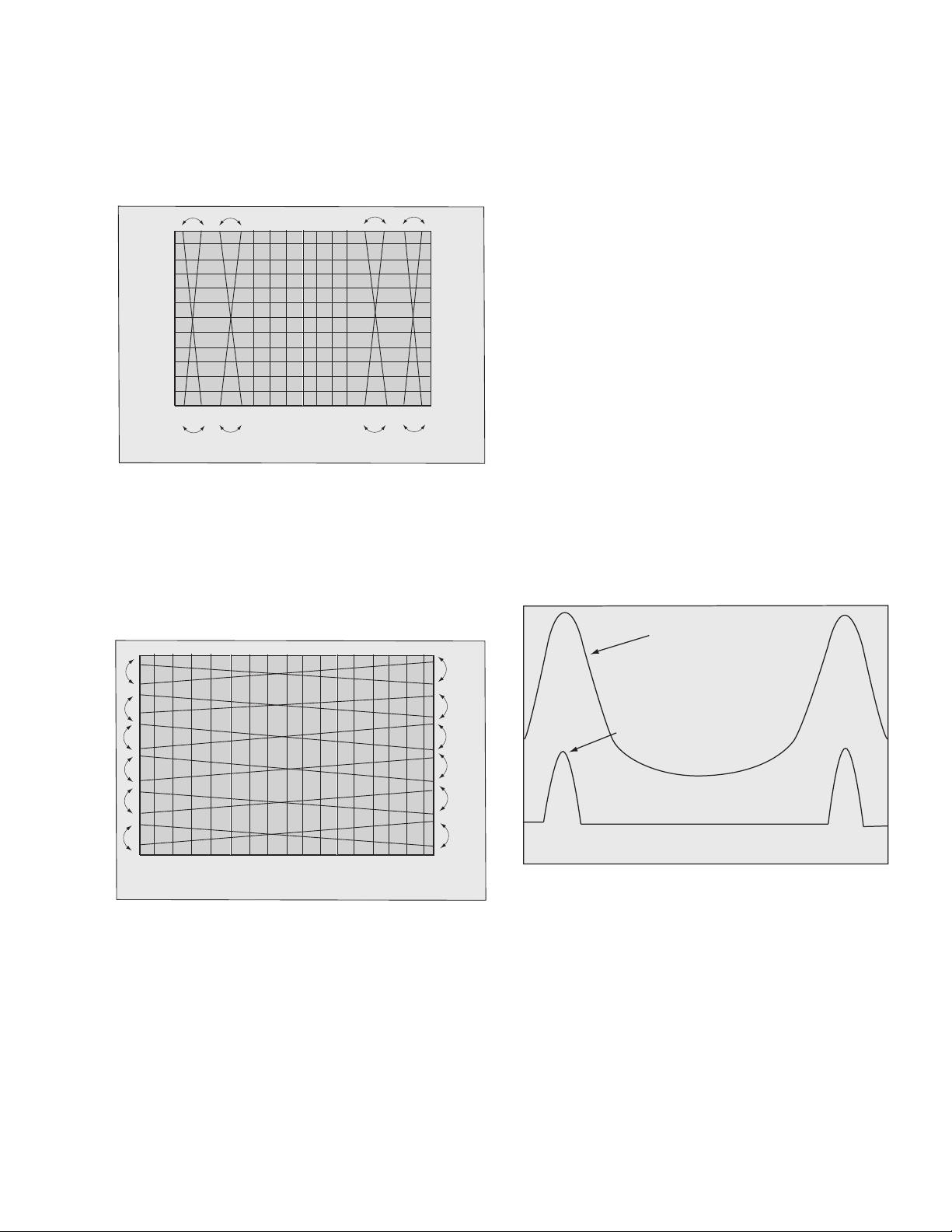
Dynamic corvergence adjustment
Use this for a precisely overall convergence adjust at
the edges.
DY(Y
HC,YV,XV) adjustment
Y
V Adjustment
(VR1 for Horizontal dynamic convergence)
1. Apply a crosshatch pattern.
2. Adjust contrast and brightness customer controls
to obtain a correct picture.
3. With a driver adjust VR1 (located in deflection yoke
board Fig. 19) to obtain a proper corvergence at
top and bottom of the screen (see Fig. 13)
B&R
G
B&R
G
B&R
-16-
G
B&R
G
Figure 13. VR1 Adjustment (YV)
H Adjustment
Y
(VR2 for vertical dynamic convergence)
1. Apply a crosshatch pattern.
2. Adjust contrast and brightness customer controls
to obtain a correct picture.
3. With a driver Adjust VR2 (located in deflection yoke
board Fig. 19) to obtain a proper corvergence at
left and right side of the screen. (see Fig. 14)
B&R
B&R
B&R
G
G
B&R
G
G
Figure 14. VR2 Adjustment (YH)
XV Adjustment
(precise adjustment)
1. Apply a crosshatch pattern.
2. Adjust contrast and brightness customer controls
to obtain a correct picture.
3. With a driver adjust the coil located in deflection
yoke board to obtain a proper convergence
horizontally.
Permalloy convergence corrector strip
(part No. 0FMK014ZZ)
Thisstripisusedinsomesetstomatchtheyokeand
CRT for optimum convergence. If the yoke or CRT is
replaced, the strip may not be required.
First converge the set without the strip and observe
the corners.
If correction is needed:
1. Place strip between CRT and yoke, in quadrant
needing correction. Slowly move it around for
desired results.
2. Press adhesive tightly to the CRT and secure
with tape.
DAF adjustment
Preparation:
1. Apply a crosshatch pattern.
2. Set user controls, bright to center and picture to
max.
3. Connect a frequency counter to TPD10.
Procedure:
1. Connect channel one of the oscilloscope with
100x1 probe to TPP33 (pin-1 T1551).
2. Connect channel two of the oscilloscope with 10x1
probe to CRT HEATER (L-Board).
3. Adjust “HDAFP” so both waves are in the same
position.
4. Adjust “HDAFW” so TPP33 is 1.5
TPP33
± 0.5kVpp.
B&R
G
B&R
G
B&R
G
B&R
G
Figure 15. XV adjustment
Note: Apply a red pattern and confirm purity, if purity
is poor, repeat purity adjustments.
HEATER
PIN
Figure 16. DAF adjustment
-17-
RGB
Figure 17. Vertical yoke movement
RGB
Figure 18. Horizontal yoke movement
Astheyokeistilted
vertically, the rasters
produced by the
outside guns rotate in
opposite directions.
Raster produced from one of the
outside electron beams
Raster from the other side electron
beam
Static convergence magnets are set for
center convergence
As the yoke is tilted horizontally, one
raster gets larger while the other gets
smaller
2Poles(VRSAdj)
4Poles
2 poles (purity)
For adjustment
of DY (Y
HC/YV/XV)
dynamic convergence
6Poles
Figure 19. Convergence magnets and convergence controls
IMPORTANT NOTE:
Always exit the service mode
following adjustments.
-18-
Service mode (electronic controls)
This receiver has electronic technology using the I²C
bus concept. It performs as a control function and it
replaces many mechanical controls. Instead of
adjusting mechanical controls individually, many of the
control functions are now performed by using “on
screen display menu”. (The service adjustment
mode).
Note: It is suggested that the technician
reads all the way through and
understand the following procedure for
entering/exiting the service
adjustment mode; then proceed with
the instructions working with the
receiver. When becoming familiar with
the procedure, the flow chart for
servicemodemaybeusedasaquick
guide.
Quick entry to service mode:
When minor adjustments need to be done to the
electronic controls, the method of entering the service
mode without removal of the cabinet back is as follows
using the remote control:
1. Select SET-UP icon and select CABLE mode.
2. Select TIMER icon and set SLEEP time for 30 Min.
3. Press “ACTION” twice to exit menus.
4. Tune to the channel 124.
5. Adjust VOLUME to minimum (0).
6. Press VOL (decrease) on receiver .Red“CHK”
appears in upper corner.+
Note: After receiver is set into service mode,
set TIMER back to NO.
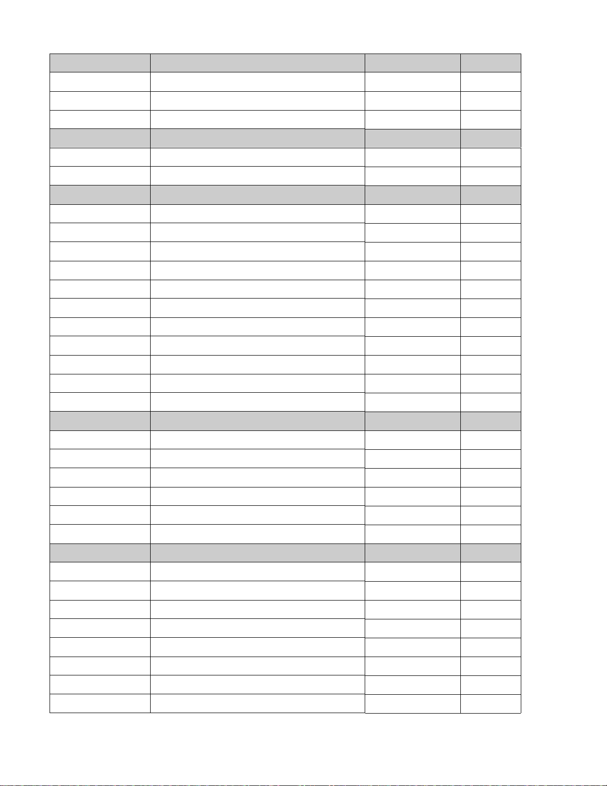
MTS MTSIN SEPAL SEPAH
CLOCK CLOCK HHSTH
VIDEO COLOR BRIGHTINT CONT
PIP PCONT
HDEF
FINE
VDEF VRAS VEAMP V-C
DAF
CTEMP
B-Y_G CUT_G CUT_R CUT_B
BRT R-DR B-DR
H-POS H-WID PCC
TOPG BTMG
PCCHG PCCLG PCCHS PCCLS
TOPSL BTMSL
HDAFS
WARMRWARMB COOLR COOLB
VDAFG
TRAP
SIDE HTRAP
V-S
VPOS
Figure 20. Service mode menu adjustments.
Exiting the service mode:
This TV goes out from service mode when it is
unplugged or turned OFF . To exit the service mode,
turn the TV OFF or unplug the TV from AC.
Other method
Press ACTION and POWER on the receiver
simultaneously for at least 2 seconds.
The receiver momentarily shuts off; then comes back
on tuned to channel 3 with a preset level of sound.
Any programmed channels, channels caption data and
some others user defined settings will be erased when
exited by pressing ACTION and POWER on receiver.
IMPORTANT NOTE:
Always check that the TV exits the
service mode.
To check colors:
Press RECALL on the remote control when in service
mode (red “CHK” is displayed) to enter the purity field
check mode.
NORMAL
SCREEN
To toggle between aging and service
modes:
While the “CHK” is displayed on the left top corner
oftheCRT,pressing“ACTION”and“VOL”uponthe
TV simultaneously will toggle between the modes.
Red “CHK” for service and yellow “CHK” for aging.
7. Press POWER on the remote control to display
the service adjustment modes menu, select
adjustment by pressing the volume right/left
buttons and channel up/down buttons on the
remote and ACTION to enter the adjustment.
Press RECALL again to select desired field.
BLUE
SCREEN
GRN.
SCREEN
RED
SCREEN
WHITE
SCREEN
Figure 21. Purity check field mode.
Helpful hints
Entering service mode (open-back method)
• While the receiver is connected and operating in
normal mode, momentarily short test point
FA1(A15pin2)to cold ground ( ) (A-Board).
The receiver enters the aging mode
Yellow letters “CHK” appear in the upper left corner of
the screen.
(The VOLUME up/down will adjust rapidly).
Note: When entering using this method, the only
waytogooutofservicemodeistopress
ACTION and POWER on the receiver
simultaneously for at least 2 seconds.
-19-
.
Service mode (electronic controls, continued)
MTS Adjustments Description Default Level New Level
MTSIN INPUT LEVEL 25
SEPAL LOW LEVEL SEPARATION 08
SEPAH HIGH LEVEL SEPARATION 1D
CLOCK Adjustments Description Default Level New Level
CLOCK CLOCK 128
HHSTH ------- FF
VIDEO Adjustments Description Default Level New Level
COLOR COLOR 01 6D
TINT TINT 4D
BRIGHT SUB-BRIGHTNESS 2D
CONT SUB-CONTRAST 60
B-Y_G MAGENTA TINT ADJ 80
CUT_G GREEN CUT-OFF 02 2D
CUT_R RED CUT-OFF 02 28
CUT_B BLUE CUT-OFF 02 23
BRT BRIGHT 2D
R DR RED DRIVE 09 68
B DR BLUE DRIVE 08 4E
HDEF Adjustments Description Default Level New Level
H POS HORIZONTAL POSITIONING 8F
H WID HORIZONTAL WIDTH 4F
PCC PINCUSHION CORRECTION 1E
TOPG TOP CORNER PINCUSHION 13
BTMG BOTTOM CORNER PINCUSHION 14
TRAP TRAPEZOID 7E
FINE Adjustments Description Default Level New Level
PCCHG PINCUSHION HIGH 15
PCCLG PINCUSHION LOW 07
PCCHS PINCUSHION HIGH OF
PCCLS PINCUSHION LOW OF
TOPSL TOP CORNER PINCUSHION SLICE LEVEL 0D
BTMSL BOTTOM CORNER PINCUSHION SLICE LEVEL OF
SIDE E-W PINCUSHION ADJUSTMENT 46
HTRAP HORIZONTAL TRAPEZOID 20
-20-
Service mode (electronic controls, continued)
VDEF Adjustment Description Default Level New Level
V RAS VERTICAL POSITION 2D
VEAMP VERTICAL SIZE BB
V-C VERTICAL LINEARITY 22
V-S VERTICAL S CORRECTION 0E
DAF Adjustments Description Default Level New Level
HDAFP HORIZONTAL DAF PHASE 00 D0
HDAFW VERTICAL DAF GAIN 60
VPOS VPOS 80
CTEMP Adjustments Description Default Level New Level
WARMR ------- 60
WARMB ------- 60
COOLR -------- 60
COOLB -------- 60
IMPORTANT NOTE:
Always exit the service mode
following adjustments.
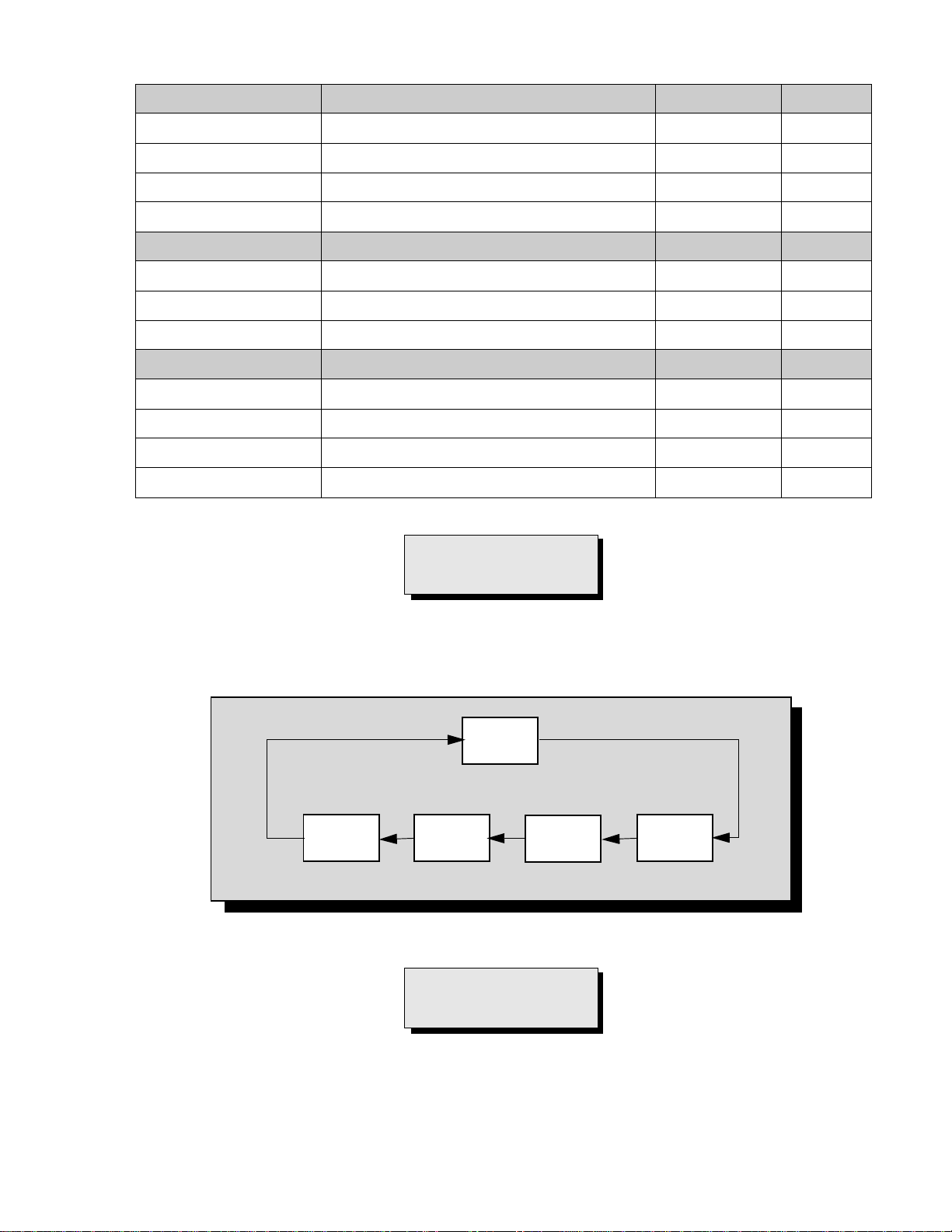
To check purity:
Press the RECA LL button on the remote control when in service mode (red “CHK” is displayed) to enter the purity
field check mode.
NORMAL
SCREEN
Press RECALL again to select desired field.
BLUE
SCREEN
GREEN
SCREEN
RED
SCREEN
Figure 22. Purity check field mode.
IMPORTANT NOTE:
Always exit the service mode
following adjustments.
WHITE
SCREEN
-21-
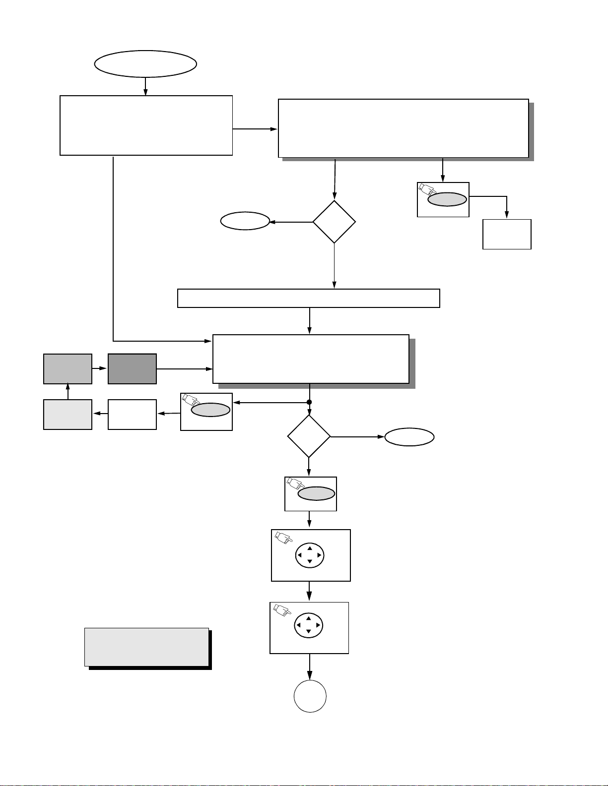
Instructional flow chart for service mode
NORMAL MODE
ENTRY TO SERVICE MODE
• Select CABLE mode.
•SetSLEEP time for 30 Min.
• Tune to Channel 124.
• Adjust VOL U ME to minimum.
•PressVOL DOWN on receiver.
To exit service mode, just unplug TV from AC line
or turn it OFF; or press ACTION and POWER on
the receiver simultaneously for at least 2 seconds.
GRN.
SCREEN
BLUE
SCREEN
AGING MODE
• Press VOL UP and ACTION simultaneously on TV
• Yellow“CHK” appears in upper left corner of screen.
• VOLUME up/down operate rapidly.
• Customer controls are set to nominal level.
Adj.
EXIT
N
needed?
Y
Press Action + Volume up simultaneously (on receiver)
SERVICE MODE
• “CHK” turns red.
• VOLUME up/down operate normally.
• Customer controls are set to nominal level.
(ON REMOTE)
RECALL
WHITE
SCREEN
RED
SCREEN
WHITE
SCREEN
(ON REMOTE)
To view the adjustments
menu press POWER on
remote.
IMPORTANT NOTE:
Always verify that TV is out
from service mode.
RECALL
Adj.
needed?
Y
POWER
(ON REMOTE)
ACTION
ACTION
(ON REMOTE)
ACTION
(ON REMOTE)
N
EXIT
To exit service mode, just unplug TV from AC line
oturnitOFF;orpressACTION and POWER on
the receiver simultaneously for at least 2
seconds.
Once in adjustments menu press
VOL right/left and CH up/down on
remote to select adjustment.
Press ACTION on remote to enter the
adjustment.
A
Figure 23.Flow chart for service mode.
-22-
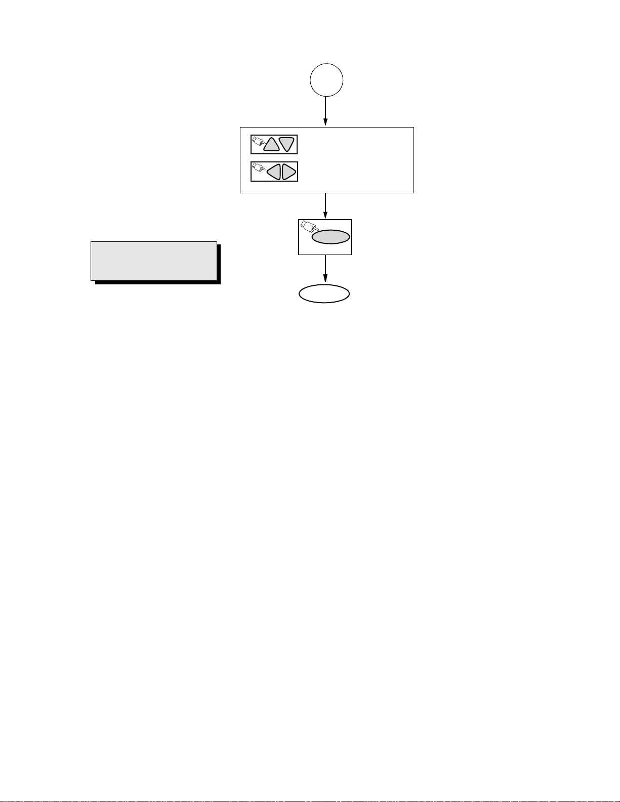
Instructional flow chart for service mode - (continued)
A
ON REMOTE CONTROL TO
CH
CH
VOL
(previous/next adjustment
ON REMOTE TO
VOL
to make adjustment
IMPORTANT NOTE:
Always verify that TV is out
from service mode.
POWER
(ON REMOTE)
Press POWER or ACTION on remote to
exit the adjustment.
EXIT
To exit service mode, just unplug TV from AC line
or turn it OFF; or press ACTION and POWER on
the receiver simultaneously for at least 2
seconds.
Figure 24. Flow chart for service mode (continued).
-23-
 Loading...