


Removable Face High-Power Cassette/Receiver with Changer Control Récepteur/lecteur de cassettes à puissance élevée avec contrôleur de changeur et panneau avant amovible Cassette de alta potencia con placa frontal Removible/Receptor con mando de cambiadiscos
 BAND
BAND
 APM
APM 
 PWR
PWR
CQ-RG153U
VO |
|
L/P |
|
US |
|
HS |
|
E |
|
L |
|
D |
|
LOU |
MUTE 1 |
|
DISC |
SCAN |
REPEAT |
RANDOM |
|
2 |
3 |
4 |
5 |
6 MONO |
CD- |
|
|
C |
TUNE |
|
TRACK |
|
DI |
SP |
|
|
CQ-RG153U
Operating Instructions Manuel d’instructions Manual de instrucciones
•Please read these instructions carefully before using this product and keep this manual for future reference.
•Prière de lire ces instructions attentivement avant d’utiliser Ie produit et garder ce manuel pour l’utilisation ultérieure.
•Lea con atención estas instrucciones antes de utilizar el producto y guarde este manual para poderlo consultar en el futuro.

|
G |
|
Safety Information |
|
|
E |
|
|
|
|
N |
|
|
|
|
L |
|
|
|
|
|
|
|
|
|
I |
|
|
|
|
S |
|
|
The following applies only in the U.S.A. |
|
|
WARNING: |
||
|
H |
|
|
|
|
|
|
TO REDUCE THE RISK OF FIRE OR ELECTRIC |
Part 15 of the FCC Rules |
|
|
|
SHOCK OR PRODUCT DAMAGE, DO NOT |
FCC Warning: |
|
|
|
EXPOSE THIS APPLIANCE TO RAIN, SPLASH- |
|
|
|
|
Any unauthorized changes or modifications to this |
|
|
|
|
ING, DRIPPING OR MOISTURE. |
|
|
|
|
equipment would void the user's authority to oper- |
|
|
|
|
|
|
|
|
|
|
ate this device. |
CAUTION:
PLEASE FOLLOW THE LAWS AND REGULATIONS OF YOUR STATE, PROVINCE OR COUNTRY FOR INSTALLATION OF THE UNIT.
NOTICE:
This product contains lead in some components. Disposal of these materials may be regulated in your community due to environmental considerations.
For disposal or recycling information please contact your local authorities, or the Electronics Industries Alliance: <http://www.eiae.org.>
Find the model number and serial number on either the back or bottom of the unit. Please record them in the space below and retain this booklet as a permanent record of your purchase to help with identification in case of theft.
MODEL NUMBER |
CQ-RG153U |
SERIAL NUMBER |
DATE PURCHASED |
|
FROM |
2
Consignes de sécurité
AVERTISSEMENT:
ATTENTION:
OBSERVEZ LES LOIS ET RÉGLEMENTS DE VOTRE DÉPARTEMENT, PROVINCE OU PAYS POUR L’INSTALLATION DE L’APPAREIL.
Información para su seguridad
ADVERTENCIA:
PELIGRO DE INCENDIOS Y
CTRICAS ASÍ COMO DE NO LO EXPONGA A LA CONDENSACIÓN DE
PRECAUCIÓN:
RESPETE LAS LEYES Y REGULACIONES DE SU ESTADO, PROVINCIA O PAÍS PARA LA INSTALACIÓN DEL APARATO.
F R A N C A I S
E S P A
Ñ
O L
Il est recommandé de noter, dans l’espace prévu cidessous, les numéros de modèle et de série inscrits soit à l’arrière soit sous le fond de l’appareil, et de conserver ce manuel comme mémorandum de l’achat afin de permettre l’identification de l’appareil en cas de vol.
NUMÉRO DE MODÈLE |
CQ-RG153U |
NUMÉRO DE SÉRIE
DATE DE L’ACHAT
VENDEUR
Busque el número del modelo y el número de serie ya sea en la parte trasera o en el fondo de la unidad. Sírvase anotar dichos números en el espacio siguiente, y mantenga este librete como una anotación permanente de su compra para ayudar en la identificación en el caso de robo.
NÚMERO DEL MODELO |
CQ-RG153U |
NÚMERO DE SERIE
FACHA DE COMPRA
NOMBRE DE LA TIENDA
3
CQ-RG153U |
CQ-RG153U |

G |
Contents |
|
E |
|
|
N |
|
|
L |
|
|
I |
Safety Information (Part 15 of the FCC Rules) . . . . . . . . . . . . . . . . . . |
page 2 |
S |
Notice . . . . . . . . . . . . . . . . . . . . . . . . . . . . . . . . . . . . . . . . . . . . . . . . . . |
. . . . 2 |
H |
|
|
|
Use this Product Safely . . . . . . . . . . . . . . . . . . . . . . . . . . . . . . . . . . . . . |
. . . 7 |
|
Accessories . . . . . . . . . . . . . . . . . . . . . . . . . . . . . . . . . . . . . . . . . . . . . . |
. . . 7 |
|
General . . . . . . . . . . . . . . . . . . . . . . . . . . . . . . . . . . . . . . . . . . . . . . |
. . . . 8 |
|
Power, volume, mute, loudness, audio mode (Bass/Treble/Balance/Fader) |
|
|
Clock Setting . . . . . . . . . . . . . . . . . . . . . . . . . . . . . . . . . . . . . . . . . . |
. . . . 9 |
|
Initial time, time reset |
|
Radio . . . . . . . . . . . . . . . . . . . . . . . . . . . . . . . . . . . . . . . . . . . . . . . . . . . 10  Radio mode, band, manual tuning, seek tuning, mono selection,
  FM
FM 
preset station setting, preset station calling, display change
Cassette Tape Player. . . . . . . . . . . . . . . . . . . . . . . . . . . . . . . . . . . . . . . 12 How to load, Rewind, Fast forward, play, eject a cassette tape and
display change
CD Changer Control. . . . . . . . . . . . . . . . . . . . . . . . . . . . . . . . . . . . . . . . 14 Play, repeat, random and scan, error messages
Note:
CD changer controls are applicable to units with an optional CD changer unit (sold separately).
Troubleshooting. . . . . . . . . . . . . . . . . . . . . . . . . . . . . . . . . . . . . . . . . . . |
16 |
Preliminary steps, if you suspect something wrong, troubleshooting tips |
|
Speaker connections . . . . . . . . . . . . . . . . . . . . . . . . . . . . . . . . . . . . . . . |
18 |
Fuse . . . . . . . . . . . . . . . . . . . . . . . . . . . . . . . . . . . . . . . . . . . . . . . . . . . . |
18 |
Product servicing . . . . . . . . . . . . . . . . . . . . . . . . . . . . . . . . . . . |
18 |
Maintenance . . . . . . . . . . . . . . . . . . . . . . . . . . . . . . . . . . . . . . . . . . . . . |
18 |
Installation Guide . . . . . . . . . . . . . . . . . . . . . . . . . . . . . . . . . . . . . . . . . 19 Installation hardware, overview, required tools, identify all leads, connect all leads, final installation, final checks, preparation, dashboard installation, to remove the unit
Anti-Theft System . . . . . . . . . . . . . . . . . . . . . . . . . . . . . . . . . . . . . . . . . 24 Place the removable face plate into case, install removable face plate
Electrical Connections . . . . . . . . . . . . . . . . . . . . . . . . . . . . . . . . . . . . . 25
Caution, wiring diagram
Specifications . . . . . . . . . . . . . . . . . . . . . . . . . . . . . . . . . . . . . . . . . . . . 26
4
Table des matières
Informations sur la sécurité (partie 15 du règlement FCC) . . . . . . . . . page 2
Utilisation de produit en sécurité. . . . . . . . . . . . . . . . . . . . . . . . . . . . . . . . 27
Accessoires . . . . . . . . . . . . . . . . . . . . . . . . . . . . . . . . . . . . . . . . . . . . . . . . 27
Généralités . . . . . . . . . . . . . . . . . . . . . . . . . . . . . . . . . . . . . . . . . . . . . . 28 Alimentation, volume, muting, compensateur physiologique et mode audio (Graves / aigus / balance / fondu)
Réglage de l'horloge. . . . . . . . . . . . . . . . . . . . . . . . . . . . . . . . . . . . . . . 29 Heure initiale et remise à l'heure
Autoradio . . . . . . . . . . . . . . . . . . . . . . . . . . . . . . . . . . . . . . . . . . . . . . . . 30 Mode autoradio, bande, syntonisation manuelle, syntonisation par
recherche, sélection mono, réglage de stations prémémorisées, rappel de FM stations prémémorisées et changement d'affichage
Lecteur de cassettes . . . . . . . . . . . . . . . . . . . . . . . . . . . . . . . . . . . . . . . 32 Chargement d'une cassette, rembobinage, avance rapide, lecture, éjection de cassette et changement d'affichage
Commande de changeur CD . . . . . . . . . . . . . . . . . . . . . . . . . . . . . . . . . 34 Lecture, relecture, lecture randomisée, exploration, messages d'erreur et changement d'affichage
Remarque: Les dispositifs de commande de changeur de CD sont applicables aux appareils équipés d'un changeur de CD optionnel (vendu séparément).
En cas de difficulté . . . . . . . . . . . . . . . . . . . . . . . . . . . . . . . . . . . . . . . . 36 Opérations préliminaires, lorsqu'on soupçonne que l'appareil ne fonctionne pas normalement et conseils pour le dépannage
Branchement des haut-parleurs . . . . . . . . . . . . . . . . . . . . . . . . . . . . . . |
38 |
Fusible. . . . . . . . . . . . . . . . . . . . . . . . . . . . . . . . . . . . . . . . . . . . . . . . . . |
38 |
Entretien du produit. . . . . . . . . . . . . . . . . . . . . . . . . . . . . . . . . . . . . . . . |
38 |
Entretien . . . . . . . . . . . . . . . . . . . . . . . . . . . . . . . . . . . . . . . . . . . . . . . . |
38 |
Guide d'installation. . . . . . . . . . . . . . . . . . . . . . . . . . . . . . . . . . . . . . . . 39 Quincaillerie pour l’installation, généralités, outils requis, identifiez tous les fils et câbles, raccordez tous les fils, installation finale, vérifications finales, préparation, installation sur le tableau de bord, comment déposer l'appareil
Système antivol. . . . . . . . . . . . . . . . . . . . . . . . . . . . . . . . . . . . . . . . . . . 44 Placer la plaque frontale dans l'étui et monter la plaque frontale amovible
Branchements électriques . . . . . . . . . . . . . . . . . . . . . . . . . . . . . . . . . . 45 Mesures de précaution et schéma de câblage
Données techniques . . . . . . . . . . . . . . . . . . . . . . . . . . . . . . . . . . . . . . . . 46
5
F R A N
Ç
A
I
S
CQ-RG153U |
CQ-RG153U |
Índice
Información para su seguridad (Parte 15 de las normativas de FCC) . . página 2
Utilización de este equipo con seguridad . . . . . . . . . . . . . . . . . . . . . . . . . 47
Accesorios . . . . . . . . . . . . . . . . . . . . . . . . . . . . . . . . . . . . . . . . . . . . . . . . . 47
Generalidades . . . . . . . . . . . . . . . . . . . . . . . . . . . . . . . . . . . . . . . . . . . . 48 Alimentación, volumen, silenciamiento, sonoridad y modo de audio (Graves/agudos/balance derecho-izquierdo/balance delantero-trasero)
Ajuste del reloj . . . . . . . . . . . . . . . . . . . . . . . . . . . . . . . . . . . . . . . . . . . 49 Hora inicial, reajuste de la hora
|
Radio . . . . . . . . . . . . . . . . . . . . . . . . . . . . . . . . . . . . . . . . . . . . . . . . . . . |
50 |
|
|
|
|
E |
Modo de la radio, banda, sintonización manual, sintonización por búsque- |
|
FM |
|
|
|
S |
da, selección de sonido monofónico, preajuste de emisoras, sintonización |
|
|
|
||
|
|
|
|
|||
P |
de emisoras preajustadas y cambio de visualización |
|
|
|
|
|
|
|
|
|
|
||
|
|
|
|
|
||
A |
|
|
|
|
|
|
Ñ |
Reproductor de cintas de casete |
52 |
|
|
|
|
O |
|
|
|
|
||
L |
Inserción de la cinta, rebobinado, avance rápido, reproducción, expulsión |
|
|
|
|
|
de la cinta y cambio de visualización
Control del cambiador de discos CD . . . . . . . . . . . . . . . . . . . . . . . . . . 54 Reproducción, repetición, reproducción aleatoria, exploración, mensajes de error y cambio de visualización
Nota: Los controles del cambiador de discos CD son aplicables a las unidades provistas de la unidad del cambiador de discos CD opcional (vendida por separado).
Solución de problemas . . . . . . . . . . . . . . . . . . . . . . . . . . . . . . . . . . . . . 56 Pasos preliminares, si cree que hay algo que no funciona bien y consejos para solucionar los problemas
Conexiones de los altavoces . . . . . . . . . . . . . . . . . . . . . . . . . . . . . . . . |
58 |
Fusible. . . . . . . . . . . . . . . . . . . . . . . . . . . . . . . . . . . . . . . . . . . . . . . . . . |
58 |
Servicio del producto . . . . . . . . . . . . . . . . . . . . . . . . . . . . . . . . . . . . . . |
58 |
Mantenimiento . . . . . . . . . . . . . . . . . . . . . . . . . . . . . . . . . . . . . . . . . . . |
58 |
Guía de instalación . . . . . . . . . . . . . . . . . . . . . . . . . . . . . . . . . . . . . . . . 59 Accesorios suministrados, perspectiva general, herramientas necesarias, identificación de todos los conductores, conexión de todos los conductores, instalación final, comprobaciones finales, preparación, instalación en el tablero de instrumentos, para extraer el aparato
Sistema antirrobo . . . . . . . . . . . . . . . . . . . . . . . . . . . . . . . . . . . . . . . . . 64 Colocación de la palca frontal extraíble en la caja e instalación de la placa frontal extraíble
Conexiones eléctricas . . . . . . . . . . . . . . . . . . . . . . . . . . . . . . . . . . . . . . 65 Precauciones y diagramas de conexiones eléctricas
Especificaciones . . . . . . . . . . . . . . . . . . . . . . . . . . . . . . . . . . . . . . . . . . 66
6
|
E |
|
N |
|
G |
Panasonic welcomes you to our ever growing family of electronic product owners. We know that this product will |
L |
I |
|
bring you many hours of enjoyment. Our reputation is built on precise electronic and mechanical engineering, man- |
S |
ufactured with carefully selected components and assembled by people who take pride in their work. Once you dis- |
H |
|
|
cover the quality, reliability, and value we have built into this product, you too will be proud to be a member of our |
1 |
family. |
|
|
Use this Product Safely
When Driving
Keep the volume level low enough to be aware of road and traffic conditions.
When Washing Your car
Do not expose the product, including the speakers and tapes, to water or excessive moisture. This could cause electrical shorts, fire, or other damage.
When Parked
Parking in direct sunlight can produce very high temperatures inside your car. Give the interior a chance to cool down before switching the unit on.
Use the Proper Power Supply
This product is designed to operate with a 12 V DC, negative ground battery system (the normal system in a North American car.)
Protect the Tape Mechanism
Keep magnets, screwdrivers, or other metallic objects away from the tape mechanism and tape head to prevent poor performance or malfunctions.
Use Authorized Servicenters
Do not attempt to disassemble or adjust this precision product. Please refer to the Servicenter list included with this product for service assistance.
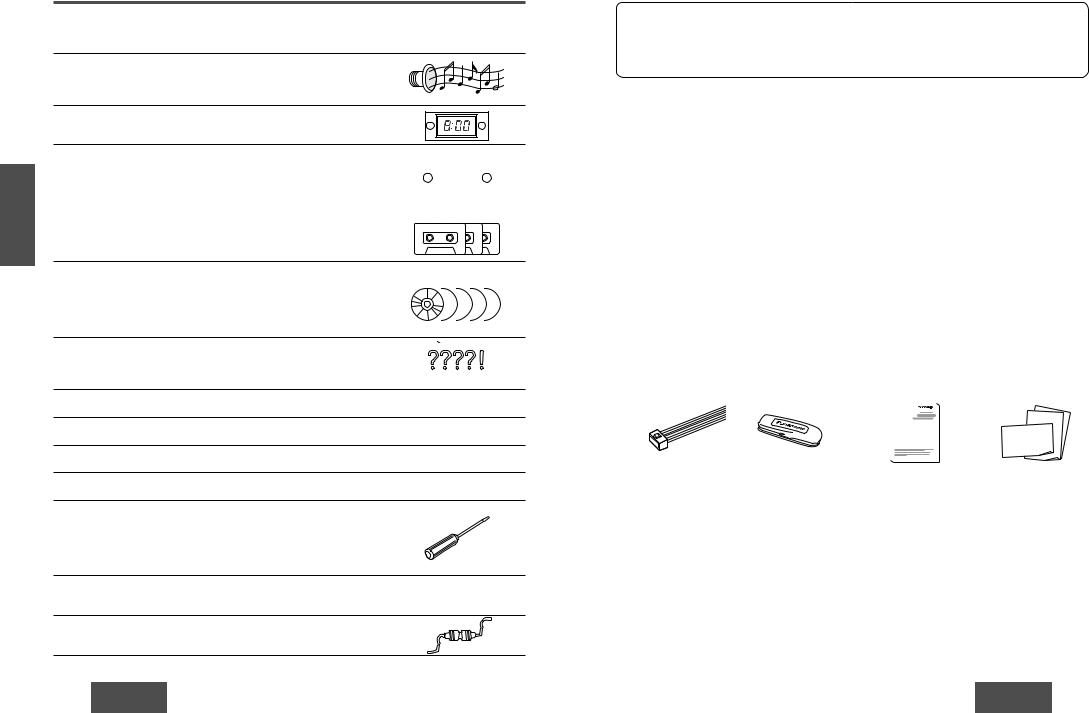
Accessories
|
|
|
|
|
|
|
|
|
|
|
|
|
|
|
|
|
|
|
|
|
|
|
|
|
|
|
|
|
|
|
|
|
|
|
|
|
|
|
|
|
|
|
|
|
|
|
|
|
|
|
|
|
|
|
• Power connector (1) |
|
• Removable face plate |
• Operating instructions (1) • Warranty card, etc. |
|||||||
|
|
case (1) |
|
|
|
|
|
|
|
|
• Operating Instructions . . . . . . . . . . . . . . . . . . . . . . . . . . . . . . . . . . . . . . . . . . . . . . . . . . . . . .1
• Supplied Hardware . . . . . . . . . . . . . . . . . . . . . . . . . . . . . . . . . . . . . . . . .(1 set ( page 19))
• The numbers in parentheses indicate the accessory quantities.
7
CQ-RG153U |
CQ-RG153U |
N
E General
G
L
I
S
H
the accesso-
2
.
again.
|
|
|
|
|
|
|
|
|
[DISP] (display) |
|
CQ-RG153U |
|
|
|
|
|
|
|
|
|
V |
|
|
|
|
|
|
|
C |
D |
OL |
|
|
|
|
|
|
|
|
|
|
|
|
|
|
|
|
D |
|
N |
H |
|
|
|
|
|
|
|
- |
|
|
|
|
|
|
|
|
C |
|
|
S |
|
|
|
|
|
|
|
|
|
E |
|
|
|
|
|
|
|
|
|
L |
|
|
|
|
|
|
|
|
|
|
|
|
|
|
|
|
|
TUNE |
|
|
|
|
|
|
|
|
|
TRACK |
|
D |
DISC |
|
SCAN |
REPEAT |
RANDOM |
|
|
P |
|
|
|
|
|
|
|
|
|
IS |
|
MUTE |
1 |
2 |
3 |
4 |
5 |
6 |
MONO |
D |
|
|
Volume
Turn the knob clockwise to increase volume, and counterclockwise to decrease volume.
Volume level (0 to 39)

 Up
Up
Down
Mute
Press [MUTE] to mute the sound completely.
Mute indicator
Press [MUTE] again to cancel.
Loudness
Press and hold for more than 2 seconds. [MUTE] (LOUD) to enhance bass and treble tones at low or medium volume.
Loudness indicator
Press and hold [MUTE] (LOUD) for more than 2 seconds again to cancel.
8
Note: If no operation takes place for more than 5 seconds in audio |
Clock Setting |
|
||||||||
G |
||||||||||
regular mode. |
|
|||||||||
mode (2 seconds in volume mode), the display returns to the |
|
E |
||||||||
|
|
|
|
|
|
|
|
|
N |
|
|
|
|
|
|
|
|
|
|
L |
|
Audio Modes |
|
|
I |
|||||||
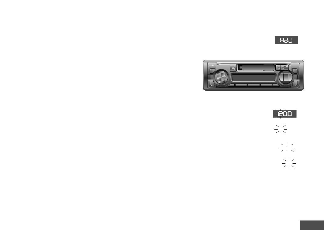
The 12-hour system is used for the clock. |
S |
|||||||||
|
|
H |
||||||||
(Bass/Treble/Balance/Fader) |
Initial Time |
3 |
||||||||
q Push [SEL] to select the audio mode. |
q Press [DISP] (clock). |
|
||||||||
|
|
|
|
|
Treble |
|
|
|
|
|


 Balance
-RG153U
VOL
H |
|
|
|
S |
|
|
|
E |
|
|
|
L |
|
|
|
D |
|
DISC |
SCAN |
LOU |
MUTE 1 |
2 |
3 |
|
“AdJ” is displayed when the clock is not adjusted.
push |
|
|
|
|
|
|
|
|
C |
|
|
|
|
D |
|
|
|
|
- |
|
|
|
|
C |
|
|
|
|
TUNE |
|
|
|
|
TRACK |
REPEAT |
RANDOM |
|
|
P |
|
|
|
|
IS |
4 |
5 |
6 |
MONO |
D |
|
||||
|
[k TUNE], [l TUNE] (Hours, minutes) |
w Turn [VOL] (volume) clockwise or counterclock- |
Hours |
wise to change each level. |
w Press and hold [DISP] (clock) for more than 2 |
Bass: |
seconds. |
default : 0 dB |
(Hours blink.) |
Adjustable range: –12 to +12 dB (by 3 dB step)
Treble:
default : 0 dB
Adjustable range: –12 to +12 dB (by 3 dB step)
Balance:
R (right speaker) or L (left speaker)
|
|
|
|
|
|
|
|
|
|
|
|
|
|
|
|
|
|
|
|
Adjustable range: |
Balance center |
|||
1 to 15 (by 1 step) |
(default) |
|||
Fader:
F (front speaker) or R (rear speaker)
|
|
|
|
|
|
|
|
|
|
|
|
|
|
|
|
|
|
|
|
|
|
|
|
|
Adjustable range: |
Fader center |
|||
1 to 15 (by 1 step) |
(default) |
|||
ePress [k TUNE] or [l TUNE].
 (Hours set.)
Minutes
rPress [DISP] (clock).  (Minutes blink.)
tPress [k TUNE] or [l TUNE].  (Minutes set.)
yPress [DISP] (clock).
 (End.)
Note: Press and hold [k TUNE] or [l TUNE] to change numbers rapidly.
Time Reset
Press and hold [DISP] (clock) for more than 2 seconds to activate the time setting mode to reset the time.
Then, repeat steps e to y.
9
CQ-RG153U |
CQ-RG153U |

E |
Radio |
|
|
N |
|
||
G |
|
||
L |
|
|
|
I |
|
|
|
S |
qChange to the Radio mode |
|
|
H |
|
||
4 |
to change to the radio mode. |
|
|
[u] (eject) to eject the tape when cassette tape play mode start. |
|||
|
|||
|
FM stereo indicator |
|
|
|
CQ-RG153U |
|
|
|
VO |
C |
|
|
L/ |
||
|
P |
D |
|
|
U |
||
|
S |
- |
|
|
H |
C |
|
|
S |
|
|
|
E |
|
|
|
L |
|
|
|
|
TUNE |
|
|
|
TRACK |
|
|
P |
LOU |
IS |
D |
wBand
Press [BAND] to change
eManual Tuning
[lTUNE]: Higher frequency [kTUNE]: Lower frequency
Seek Tuning
Press and hold ...
[lTUNE]: Higher frequency [kTUNE]: Lower frequency Tuning will automatically
of the next broadcast station
rMono Selection
Press [MONO] for monaural reception in case a lot of interference is present in an FM stereo signal or to improve the listening quality of weak FM broadcasts.
Press [MONO] again to cancel.
MONO indicator
10
E
N
G
L
I
Preset Station Setting Display Change S
H
Up to 6 stations can be saved in each of the FM1, FM2, |
Press [DISP] (display) to switch to the clock display. |
FM3 and AM preset station memories. |
5 |
|
Note: Existing saved stations are overwritten with new |
|
|
Frequency |
|
|
Clock display |
||||||
stations after following this procedure. |
|
|
|
|
|
|
|
|
||||
qBand |
|
|
|
|
|
|
|
|
|
|
|
|
to select a desired band. |
|
|
|
|
|
|
|
|
||||
|
CQ-RG153U |
|
|
|
|
|
|
|
|
|
|
|
|
VO |
|
|
|
|
|
|
|
|
C |
|
|
D |
L/ |
|
|
|
|
|
|
|
|
|
|
|
P |
|
|
|
|
|
|
|
|
|
- |
||
N |
S |
|
|
|
|
|
|
|
|
|
||
A |
U |
|
|
|
|
|
|
|
|
D |
|
|
H |
|
|
|
|
|
|
|
|
|
C |
||
B |
S |
|
|
|
|
|
|
|
|
|
|
|
APM |
E |
|
|
|
|
|
|
|
|
|
|
|
|
L |
|
|
|
|
|
|
|
|
|
|
|
|
|
|
|
|
|
|
|
|
TUNE |
|
|
|
|
|
|
|
|
|
|
|
|
TRACK |
|
|
|
PWR |
D |
|
|
DISC |
SCAN |
REPEAT |
RANDOM |
|
|
I |
P |
|
|
LOU |
|
|
|
|
|
|
|
|
D |
S |
|
|
MUTE |
1 |
22 |
3 |
44 |
5 |
6 |
MONO |
|
|
||
|
|
|
|
|
||||||||
Preset buttons from [1] to [6]
wAuto Preset Memory (APM)
Press and hold [BAND] (APM: auto preset than 2 seconds.
•The 6 stations with good reception will be saved in the memory under preset buttons from
•Once set, the preset stations are sequentially seconds each.
Manual Preset Memory
qUse manual or seek tuning to find a station. (
wPress and hold one of the preset buttons until the display blinks once.
Preset Station Calling
Press the corresponding preset button from [1] to [6] to tune in a preset station.
blinks once
Caution: To ensure safety, never attempt to preset stations while you are driving.
11
CQ-RG153U |
CQ-RG153U |
E N G L I S H
6
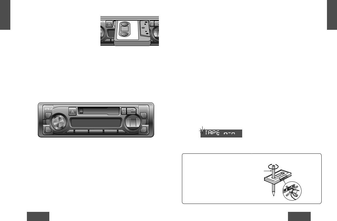
Cassette Tape Player
qLoading a Cassette
Gently insert a cassette with the exposed tape side facing to the right until the mechanism captures it, and playback starts.
Program Indicator
(This indication “ ” rotates.)
RG153U
VOL/P
U
S
H
S
E
L
|
|
T |
|
|
T |
D |
|
|
LOU |
MUTE |
1 |
|
Exposed Tape side |
wPlay Side Change |
|
|
|
Press [a] and [f] at the same time to switch to the program on the other side of the tape. |
|
The display changes to indicate which program is playing. |
|
|
|
|
|
|
|
|
|
|
|
|
|
|
|
Top Side Playing |
Bottom Side Playing |
|||
E N G L I S H
7
CQ-RG153U
|
|
|
C |
|
|
|
D |
|
|
|
- |
|
|
|
C |
|
|
|
TUNE |
|
|
|
TRACK |
DISC |
SCAN |
REPEAT RANDOM |
SP |
|
|
|
Stop and Eject
Once inserted into the unit,
If you press [u] (eject), the
When you stop the car engine,
Notes:
•You can not change to CD If you want to change to CD
•Always remove the cassette prolong the life of your tape
Display Change
Press [DISP] (display) to switch to the clock display.
|
|
Clock display |
Tape |
||
12
eRewind and Fast Forward
When the program indicator i lights, press [a] to rewind or press [f] to fast forward the tape.
When the program indicator o lights, press [a] to fast forward or press [f] to rewind the tape.
blinks
To stop rewind or fast forward, gently press the button that is not in use.
The tape will resume playing from that position.
Note: To maintain your cassette player in top condition, avoid using tapes that are longer than 90 minutes (C-90).
Notes on Cassette Tapes
Tape Slack: |
Pencil |
Use a pencil or similar object to take up the slack as shown. If a loose tape is used, this may result in the tape becoming tangled in the rotating parts of the unit.
 Exposed end (Open end)
Do not touch or pull out the tape.
13
CQ-RG153U |
CQ-RG153U |

|
G |
CD Changer Control |
|
E |
|
|
N |
|
|
L |
|
|
I |
qCD Changer mode |
|
S |
|
|
H |
While a disc magazine is inserted |
|
8 |
|
|
Play starts from the first track. |
|
|
|
Note: The cassette, if |
|
|
removed. Otherwise, the CD |
D |
L/ |
P |
|
N |
S |
A |
U |
H |
|
B |
S |
APM |
E |
|
L |
C  D -
D -  C
C
TUNE
 TRACK
TRACK 

 SP
SP
wDisc Selection
[1](iDISC): Previous disc
[2](jDISC): Next disc.
eTrack Selection
Press [TRACK 7] repeatedly to step forward Press [TRACK 6] current track, Press repeatedly to step backward
lights when a CD changer is connected.
Track Search
Press and hold [TRACK 7 0.5 second to activate fast track. Release [TRACK 7 normal CD play from that
Display Change
Press [DISP] (display) to switch to the clock display.
|
|
CD Changer |
Clock display |
14
Note: CD changer functions are applicable to units with optional CD changer unit (sold separately).
Scan Play
(Tracks)
Scan Play
(Discs)
Repeat Play
Random
Play
DISC No.
• Press [3] (SCAN). The track number blinks and |
|
|
|||
the first 10 seconds of each track on the discs |
|
|
|
|
|
|
|
|
|
|
|
play in sequence. |
|
|
|
|
|
• Press [3] (SCAN) again to cancel and continue |
|
|
|
|
|
|
|
|
blinks |
|
|
with the current track. |
|
||||
• Press and hold [3] (SCAN) for more than 2 sec- |
|
|
|||
onds. The first track of all the discs in the maga- |
|
|
|||
zine is played for 10 seconds each and Disc |
|
|
|
|
|
Number blinks. |
|
|
|
|
|
• Press and hold [3] (SCAN) for more than 2sec- |
|
|
|
blinks |
|
onds again to cancel. |
|
||||
|
|
||||
• Press [4] (REPEAT) to repeat the current selec- |
lights |
REP: Repeat indicator |
|
||
|
|
|
|
||
tion. |
|
|
|
|
|
|
|
|
|
||
• Press [4] (REPEAT) again to cancel. |
|
|
|
|
|
lights
• Press [5] (RANDOM) to random selection of
music is played from all available CDs.
• Press [5] (RANDOM) again to cancel. 
 R 5: Random indicator
Disc is dirty, or is upside down.
Select the next available compact disc. Check the disc.
Disc has scratches.
Select the next available compact disc. Check the disc.
E N G L I S H
9
DISC No.
No operation by some cause.
Eject the magazine. If failure persists, press the reset switch on the CD changer. If normal operation is not restored yet, call the store where you purchased the unit.
No disc in the changer (magazine)
Insert discs into the changer (magazine).
15
CQ-RG153U |
CQ-RG153U |

E
N
G
L
I
S
H
10
Troubleshooting
Preliminary Steps
Check and take steps as described in the tables below.
If You Suspect Something Wrong
Immediately switch the power off.
Disconnect the power connector and check that there is neither smoke nor heat from the unit
repairs. Never try to repair the unit by is dangerous to do so.
Cautions:
•Do not use the unit if it malfunctions or if there is something wrong.
•Do not use the unit in irregular condition, for example, without sound, or with smoke or foul smell, which can cause ignition or electric shock. Immediately stop using it and call the store where you purchased it.
Troubleshooting Tips
Common
Noise.
Cause/Step
Car’s ignition
Turn your car’s
Cables are not
Connect cables
Battery cable is
Connect the
Accessory cable is
Connect the
Grounding wire is
Connect the
Fuse is burnt.
Consult the replacement.
Mute is set to ON.
Set it to OFF.
Cables are not correctly connected.
Connect cables correctly.
The ground lead is not connected properly.
Connect the ground lead properly.
Radio
Cause/Step
Battery cable is not correctly connected.
Connect the battery cable to the terminal that is always active.
Cassette Tape
Sound Setting
Trouble
No sound from left, right, front, or rear speaker.
Left and right sounds are reversed in stereo listening.
Cause/Step
Blank tape is inserted in the unit.
Insert recorded tape into the unit.
Heads are dirty.
Clean heads. (Ask a service representative for advice.)
Poor quality tape.
Use better quality tape.
Heads are magnetized.
Demagnetize heads. (Ask a service representative for advice.)
Tape running mechanism is dirty or out of order.
Clean tape running mechanism, or repair it. (Ask a service representative for advice.)
Cause/Step
Left and right balance, or front and rear balance is off on one side.
Adjust BAL/FAD as appropriate.
Cables are not correctly connected.
Connect the cables correctly.
The right speaker wire is connected to the left speaker and the left speaker wire to the right speaker.
Connect the speaker wires to the correct one.
16 |
17 |
E N G L I S H
CQ-RG153U |
CQ-RG153U |

|
E |
|
Speaker Connections |
|
|
|
|
|
|
|
|
|
|||||||||||||||||
|
N |
|
|
|
|
|
|
|
|
|
|
||||||||||||||||||
|
G |
|
|
|
|
|
|
|
|
|
|
||||||||||||||||||
|
L |
|
|
|
|
|
|
|
|
|
|
|
|
|
|
|
|
|
|
|
|
|
|
|
|
|
|
|
|
|
|
|
|
|
|
|
|
|
|
|
|
|
|
|
|
|
|
|
|
|
|
|
|
|
|
|
|
|
|
|
I |
|
|
|
|
|
|
|
|
|
|
|
|
|
|
|
|
|
|
|
|
|
|
|
|
|
|
|
|
|
S |
|
|
Caution: Please follow the instructions given below. Failure to do so will cause damage to the unit and speakers. |
|||||||||||||||||||||||||
|
H |
|
|
||||||||||||||||||||||||||
|
12 |
|
|
|
|
|
<Right> |
• Use ungrounded speaker only. |
|
|
|
|
|
|
|
||||||||||||||
|
|
|
|
|
|
|
|
|
|
|
|
|
|
||||||||||||||||
|
|
|
|
|
|
|
|
|
|
|
|
|
|
||||||||||||||||
|
|
|
|
|
|
|
|
|
(White) |
• The maximum speaker input should be 45 W or more. |
(If used with the optional |
||||||||||||||||||
|
|
|
|
L |
+ |
|
|
|
|
|
|
|
|
|
+ |
power amplifier, the speaker input should be higher than the maximum amplifier |
|||||||||||||
|
|
|
|
|
|
|
|
|
|
|
|
|
- |
||||||||||||||||
|
|
|
|
|
- |
|
(White |
output.) |
|
|
|
|
|
|
|
|
|
||||||||||||
|
|
|
|
|
|
|
|
w/black stripe) |
|
|
|
|
|
|
|
|
|
||||||||||||
|
|
|
|
|
|
|
|
• The speaker impedance should be 4 - 8 Ω . |
|
|
|
|
|
|
|
||||||||||||||
|
|
|
|
|
|
|
|
|
|
|
|
|
|
|
|
|
|
|
|
|
|
|
|
|
|||||
|
|
|
|
|
+ |
|
|
|
(Gray) |
• This unit uses the BTCL circuit, so each speaker should be connected separately |
|||||||||||||||||||
|
|
|
|
|
|
|
|
|
|
|
|
|
|
+ |
|
|
|
|
|
|
|
|
|
|
|
|
|||
|
|
|
|
R - |
|
|
|
|
|
|
|
|
|
- |
using parallel vinyl insulated cords. |
|
|
|
|
|
|
|
|||||||
|
|
|
|
|
|
|
|
|
|
|
|
|
|
|
|
|
|
|
|
||||||||||
|
|
|
|
|
|
|
(Gray |
|
|
|
|
|
|
|
|||||||||||||||
|
|
|
|
|
|
|
|
• The speaker cords and the power amplifier unit should be kept away (about 30 cm |
|||||||||||||||||||||
|
|
|
|
|
|
|
|
w/black stripe) |
|||||||||||||||||||||
|
|
|
|
|
|
|
|
|
|
|
|
|
|
|
|
|
|
apart) from the antenna and antenna extension cord. |
|
|
|
|
|
|
|
||||
|
|
|
|
|
|
<Wrong> |
|
|
|
|
|
|
|
|
|
|
|
|
|
||||||||||
|
|
|
|
|
|
|
|
|
|
+ |
|
|
|
|
|
|
|
|
|||||||||||
|
|
|
|
|
|
|
|
|
|
|
|
|
|
|
|
|
|
|
|
|
|
|
|
|
|
|
|
||
|
|
|
|
|
|
|
|
|
|
|
|
|
|
|
|
|
|
|
|
|
|
|
|
|
|
|
+ |
|
|
|
|
|
|
|
+ |
|
|
|
|
|
|
|
|
+ |
|
+ |
|
|
+ |
|
|
+ |
|
||||||
|
|
|
|
L |
- |
|
|
|
|
|
|
|
|
- |
|
L - |
|
- |
|
L - |
|
|
- |
|
- |
|
|||
|
|
|
|
|
|
|
|
Chassis |
|
|
|
|
|
|
|
|
|
|
|
|
|||||||||
|
|
|
|
|
+ |
|
|
|
|
|
|
+ |
|
+ |
|
+ |
|
+ |
|
|
+ |
|
+ |
|
|||||
|
|
|
|
R - |
|
|
|
|
|
|
|
|
- |
|
R - |
|
- |
|
R - |
|
|
- |
|
- |
|
||||
Chassis |
|
|
• Never connect the speaker cord to |
• Do not use a 3-wire type speaker |
• Do not connect more than one |
the body of the car. |
system having a common earth |
speaker to one set of speaker |
|
lead. |
leads. |
Fuse
Use fuses of the same specified rating (15 A). Using different substitutes or fuses with higher ratings, or connecting the unit directly without a fuse, could cause fire or damage to the unit.
If the fuse replacement fails, contact your nearest authorized Panasonic Service Center.
Product Servicing
If the suggestions in the charts do not solve the problem, we recommend that you take it to your nearest authorized Panasonic Servicenter. The product should be serviced only by a qualified technician.
Maintenance
Your product is designed and manufactured to ensure the minimum of maintenance. Use a soft cloth for routine exterior cleaning. Never use benzine, thinner, or other solvents.
18
Installation Guide
 WARNING
This installation information is designed for experienced installers and is not intended for non-technical individuals. It does not contain warnings or cautions of potential dangers involved in attempting to install this product.
Any attempt to install this product in a motor car by anyone other than qualified installer could cause damage to the electrical system and could result in serious personal injury or death.
Installation Hardware
No. |
Item |
Diagram Q’ty |
q Mounting collar |
1 |
|
w Hex. nut (5 mmø) |
1 |
|
e Rear support strap |
1 |
|
r |
Tapping screw |
1 |
(5 mmø × 16 mm) |
||
t Mounting bolt (5 mmø) |
1 |
|
y Power connector |
1 |
|
u Dismounting plate |
2 |
|
i Trim plate |
1 |
|
If you encounter problems, please consult your nearest professional installer.
Caution: This unit operates with a 12 V DC negative ground auto battery system only. Do not attempt to use it in any other system. Doing so could cause serious damage.
12 V DC |
Electrical tape |
Side-cut |
Test bulb |
|
pliers |
Overview
This product should be installed by a professional. However, if you plan to install this product yourself, your first step is to decide where to install it. The instructions in these pages will guide you through the remaining steps:
(Please refer to the “WARNING” statement above.)
•Identify and label the car wires.
•Connect the car wires to the wires of the power connector.
•Install the unit in the dashboard.
• Check the operation of the unit. |
19 |
E
N
G
L
I
S
H
13
CQ-RG153U |
CQ-RG153U |
|
G |
|
Installation Guide (Continued) |
|
|
|
|
|
|
|
|
|
|
|
E |
|
|
|
|
|
|
|
|
|
|
|
|
|
N |
|
|
|
|
|
|
|
|
|
|
|
|
|
L |
|
|
|
|
|
|
|
|
|
|
|
|
|
|
|
|
|
|
|
|
|
|
|
|
|
|
|
I |
|
Identify All Leads |
|
|
Final Checks |
|||||||
|
S |
|
If your car is not wired for an audio unit: |
Speakers |
|||||||||
|
H |
|
Go to the fuse block and find the fuse port for the bat- |
Connect the speaker wires. See the wiring diagram |
|||||||||
|
|
|
The first step in installation is to identify all the car wires |
1. |
Make sure that all wires are properly connected and |
||||||||
|
14 |
|
tery, usually marked BAT. |
( page 25) for the proper hookups. Follow the diagram |
|||||||||
|
|
you’ll use when hooking up your sound system. |
|
insulated. |
|||||||||
|
|
|
carefully to avoid damaging the speakers and the stereo |
|
|||||||||
|
|
|
As you identify each wire, we suggest that you label it |
Speakers |
2. |
Make sure that the stereo unit is securely held in the |
|||||||
|
|
|
unit. |
||||||||||
|
|
|
using masking tape and a permanent marker. This will |
Identify the car speaker leads. There are two leads for |
|
mounting collar. |
|||||||
|
|
|
The speakers used must be able to handle more than 45 |
|
|||||||||
|
|
|
help avoid confusion when making connections later. |
each speaker which are usually color coded. |
3. Turn on the ignition to check the unit for proper |
||||||||
|
|
|
W of audio power. If using an optional audio amplifier, |
||||||||||
|
|
|
Note: Do not connect the power connector to the stereo |
|
|
operation. |
|||||||
|
|
|
A handy way to identify the speaker leads and the speak- |
the speakers should be able to handle the maximum |
|
||||||||
|
|
|
|
|
|
|
|
|
|
|
|||
|
|
unit until you have made all connections. If there are no |
er they are connected with is to test the leads using a |
amplifier output power. Speakers with low input ratings |
If you have difficulties, consult your nearest author- |
||||||||
|
|
plastic caps on the stereo hooking wires, insulate all |
1.5 V AA battery as follows. |
can be damaged. Speaker impedance should measure |
ized professional installer for assistance. |
||||||||
|
|
exposed leads with electrical tape until you are ready to |
Hold one lead against one pole of the battery and stroke |
4–8 Ω , which is typically marked on most speakers. |
Preparation |
||||||||
|
|
use them. Identify the leads in the following order. |
Lower or higher impedance speakers will affect output |
||||||||||
|
|
the other lead across the other pole. You will hear a |
|||||||||||
|
|
|
Power Lead |
and can cause both speaker and stereo unit damage. |
|
|
|
|
|
|
|
|
|
|
|
|
scraping sound in one of the speakers if you are holding |
|
|
• We strongly recommend that you wear gloves for |
|||||||
|
|
|
If your car has a radio or is pre-wired for one: |
a speaker lead. |
Battery |
|
|||||||
|
|
|
|
installation work to protect yourself from injuries. |
|||||||||
|
|
|
Cut the connector wires one at a time from the plug |
|
Connect the yellow battery lead to the correct radio wire |
|
|||||||
|
|
|
If not, keep testing different lead combinations until you |
|
• When bending the mounting tabs of the mounting |
||||||||
|
|
|
(leaving the leads as long as possible) so that you can |
or to the battery fuse port on the fuse block. |
|
||||||||
|
|
|
|
collar with a screwdriver, be careful not to injure |
|||||||||
|
|
|
work with individual leads. |
have located all the speaker leads. When you label them, |
|
|
|||||||
|
|
|
Antenna |
|
your hands and fingers. |
||||||||
|
|
|
|
include the speaker location for each. |
|
||||||||
|
|
|
|
Antenna |
Connect the antenna by plugging the antenna lead into |
|
|
|
|
|
|
|
|
|
|
|
|
the antenna receptacle. |
|
|
|
|
|
|
|
|
|
|
|
|
|
The antenna lead is a thick, black wire with a metal plug |
Equipment |
|
|
|
|
|
|
|
|
|
|
|
|
at the end. |
|
|
|
|
|
|
|
|
|
|
|
|
|
|
Connect any optional equipment such as an amplifier, |
|
|
|
|
|
|
|
|
|
|
|
|
|
according to the instructions furnished with the equip- |
|
|
|
|
|
|
|
|
|
|
|
|
|
ment. Leave about 12" (30 cm) of distance between the |
|
|
|
|
|
|
|
|
|
|
|
Turn the ignition on to the accessory position, and |
|
speaker leads/amplifier unit and the antenna/antenna |
|
|
|
|
|
|
|
|
|
|
|
|
extension cord. Read the operating and installation |
|
|
|
|
|
|
|
|
|
|
|
|
ground one lead of the test bulb to the chassis. |
|
|
|
|
|
|
|
|
|
|
|
|
|
|
instructions of any equipment you will connect to this |
|
|
|
|
|
|
|
|
|
|
|
|
|
|
|
|
|
|
|
|
|
|
|
|
|
|
Touch the other lead of the test bulb to each of the |
|
unit. |
|
|
|
|
|
|
|
|
|
|
|
Connect All Leads |
|
|
|
|
|
|
|
|
|
|
|
|
|
exposed wires from the cut radio connector plug. Touch |
Power |
|
|
|
|
|
|
|
|
|
|
|
|
|
|
|
|
|
|
|
||||
|
|
|
one wire at a time until you find the outlet that causes |
Now that you have identified all the wires in the car, you |
Connect the red power lead to the correct car radio wire |
|
|
|
|
|
|
|
|
|
|
|
the test bulb to light. |
|
|
|
|
|
|
|
|
||
|
|
|
are ready to begin connecting them to the stereo unit |
or to the appropriate fuse port on the fuse block. |
|
Caution: Do not disconnect the battery terminals of |
|||||||
|
|
|
|
|
|||||||||
|
|
|
Now turn the ignition off and then on. If the bulb also |
wires. The wiring diagram ( page 25) shows the prop- |
If the stereo unit functions properly with all these con- |
|
|||||||
|
|
|
|
a car with a trip or navigational computer since all |
|||||||||
|
|
|
turns off and on, that outlet is the car power lead. |
er connections and color coding of the leads. |
nections made, disconnect the wires and proceed to the |
|
|||||||
|
|
|
|
user settings stored in memorywill be lost. Instead |
|||||||||
|
|
|
|
We strongly recommend that you test the unit before |
final installation. |
|
|||||||
|
|
|
If your car is not wired for an audio unit: Go to the fuse |
|
take extra care with installing the unit to prevent |
||||||||
|
|
|
making a final installation. |
|
|
||||||||
|
|
|
|
|
shorts. |
||||||||
|
|
block and find the fuse port for radio (RADIO), accesso- |
You can set the unit on the floor and make temporary |
|
|
||||||||
|
|
|
|
|
|
|
|
|
|
|
|||
|
|
ry (ACC), or ignition (IGN). |
connections to test the unit. Use electrical tape to cover |
|
|
|
|
|
|
|
|
|
|
|
|
|
Battery Lead |
all exposed wires. |
|
|
|
|
|
|
|
|
|
|
|
|
|
|
|
|
|
|
|
|
|
|
|
|
|
|
If your stereo unit has a yellow lead, you will need to |
|
|
|
|
|
|
|
|
|
|
|
|
|
locate the car’s battery lead. Otherwise you may ignore |
Important: Connect the red power lead last, after |
Final Installation |
|
|
|
|
|
|
|
|
|
|
|
this procedure. (The yellow battery lead provides contin- |
|
|
|
|
|
|
|
|
||
|
|
|
|
|
|
|
|
|
|
||||
|
|
|
uous power to maintain a clock, memory storage, or |
you have made and insulated all other connections. |
Lead Connections |
|
|
|
|
|
|
|
|
|
|
|
|
|
|
|
|
|
|
||||
|
|
|
other function.) |
|
|
|
|
|
|
|
|
|
|
|
|
|
If your car has a radio or is pre-wired for one: |
|
Connect all wires, making sure that each connection is |
|
|
|
|
|
|
|
|
|
|
|
|
insulated and secure. Bundle all loose wires and fasten |
|
|
|
|
|
|
|
|
|
|
|
|
With the ignition and headlights off, identify the car bat- |
|
them with tape so they will not fall down later. Now |
|
|
|
|
|
|
|
|
|
|
|
tery lead by grounding one lead of the test bulb to the |
|
insert the stereo unit into the mounting collar. |
|
|
|
|
|
|
|
|
|
|
|
chassis and checking the remaining exposed wires from |
|
Congratulations! After making a few final checks, you’re |
|
|
|
|
|
|
|
|
|
|
|
the cut radio connector plug. |
|
|
|
|
|
|
|
|
|
|
|
|
|
|
|
ready to enjoy your new auto stereo system. |
|
|
|
|
|
|
|
|
|
|
20 |
|
|
|
|
21 |
||||||
E
N
G
L
I
S
H
15
CQ-RG153U |
CQ-RG153U |
 Loading...