


VBA28001-R.3813.A
VBA28001
REPAIR MANUAL
Copyright © 2010 by Nikon Corporation. All Rights Reserved.
!!
Printed in Japan March 2010
User ID:INC
|
VBA28001-R.3813.A |
|
Contents |
Disassembly......................................................................................................................... |
D1 |
Warning........................................................................................................................................................ |
D1 |
1. External Appearance.................................................................................................................. |
D2 |
Rear cover unit............................................................................................................................................. |
D2 |
Front cover unit............................................................................................................................................ |
D6 |
Discharge of main condenser....................................................................................................................... |
D7 |
Top cover unit.............................................................................................................................................. |
D8 |
2. Rear Cover.................................................................................................................................. |
D9 |
SD cover unit............................................................................................................................................... |
D9 |
LCD monitor cover.................................................................................................................................... |
D10 |
Eyepiece..................................................................................................................................................... |
D10 |
Retainer plate............................................................................................................................................. |
D11 |
Speaker....................................................................................................................................................... |
D12 |
Rear FPC.................................................................................................................................................... |
D12 |
LCD monitor.............................................................................................................................................. |
D13 |
Rear button................................................................................................................................................. |
D13 |
LV lever...................................................................................................................................................... |
D14 |
TFT sponge................................................................................................................................................ |
D14 |
SD access lamp window............................................................................................................................ |
D14 |
3. Top Cover.................................................................................................................................. |
D15 |
SB release PCB unit................................................................................................................................... |
D15 |
SB upper cover........................................................................................................................................... |
D17 |
SB lower cover unit................................................................................................................................... |
D17 |
AF assist lamp unit.................................................................................................................................... |
D19 |
Top cover FPC unit.................................................................................................................................... |
D20 |
Command dial unit..................................................................................................................................... |
D21 |
Info & "+ -" aperture button....................................................................................................................... |
D21 |
ON-OFF dial.............................................................................................................................................. |
D22 |
Mode dial unit............................................................................................................................................ |
D23 |
Hot shoe..................................................................................................................................................... |
D24 |
Prism box unit............................................................................................................................................ |
D25 |
Screen......................................................................................................................................................... |
D26 |
SI (super impose) display plate.................................................................................................................. |
D26 |
LCD unit.................................................................................................................................................... |
D27 |
G7 lens unit................................................................................................................................................ |
D27 |
4. Sub-frame (tentative)............................................................................................................... |
D29 |
Main condenser.......................................................................................................................................... |
D29 |
IF holder..................................................................................................................................................... |
D29 |
TOGO PCB unit......................................................................................................................................... |
D30 |
Battery box unit......................................................................................................................................... |
D31 |
|
- D3100 - |
User ID:INC
|
VBA28001-R.3813.A |
Shield plate unit......................................................................................................................................... |
D35 |
SZ-DC/DC PCB unit................................................................................................................................. |
D36 |
Sub-frame................................................................................................................................................... |
D37 |
Bottom plate unit....................................................................................................................................... |
D38 |
5. Front Body................................................................................................................................. |
D41 |
Image sensor unit....................................................................................................................................... |
D41 |
Shutter PCB............................................................................................................................................... |
D42 |
MG PCB unit............................................................................................................................................. |
D47 |
SQ PCB unit............................................................................................................................................... |
D48 |
Bayonet mount........................................................................................................................................... |
D49 |
F-min SW................................................................................................................................................... |
D51 |
Lens contact unit........................................................................................................................................ |
D51 |
AF sensor unit............................................................................................................................................ |
D53 |
Lens release button unit............................................................................................................................. |
D53 |
Mirror unit.................................................................................................................................................. |
D54 |
Assembly.............................................................................................................................. |
A1 |
1. Front Body................................................................................................................................... |
A1 |
Mirror unit.................................................................................................................................................... |
A1 |
Lens release button unit............................................................................................................................... |
A2 |
AF sensor unit.............................................................................................................................................. |
A2 |
Lens contact unit.......................................................................................................................................... |
A3 |
F-min SW..................................................................................................................................................... |
A5 |
Bayonet mount............................................................................................................................................. |
A5 |
SQ PCB unit................................................................................................................................................. |
A7 |
Height adjustment of aperture lever............................................................................................................. |
A8 |
MG PCB unit............................................................................................................................................... |
A8 |
Shutter PCB............................................................................................................................................... |
A10 |
Adjustment of shutter curtain speed.......................................................................................................... |
A14 |
Inspection and adjustment of flange-back (body-back)............................................................................. |
A15 |
Image sensor unit....................................................................................................................................... |
A16 |
2. Sub-frame.................................................................................................................................. |
A18 |
Bottom plate unit....................................................................................................................................... |
A18 |
Radiating sheet for repair........................................................................................................................... |
A21 |
Sub-frame................................................................................................................................................... |
A22 |
SZ-DC/DC PCB unit................................................................................................................................. |
A23 |
Sub-frame unit........................................................................................................................................... |
A24 |
Battery box unit......................................................................................................................................... |
A26 |
TOGO PCB unit......................................................................................................................................... |
A30 |
G7 lens unit................................................................................................................................................ |
A31 |
LCD unit.................................................................................................................................................... |
A33 |
SI (super impose) display plate.................................................................................................................. |
A34 |
- D3100 - |
|
User ID:INC
|
VBA28001-R.3813.A |
Screen......................................................................................................................................................... |
A34 |
Prism box unit............................................................................................................................................ |
A35 |
Angle adjustment of main mirror and sub-mirror...................................................................................... |
A35 |
Inspection and adjustment of "∞ (infinity)" focus.................................................................................... |
A36 |
IF holder..................................................................................................................................................... |
A36 |
Main condenser.......................................................................................................................................... |
A37 |
Inspection for AE-CCD positioning.......................................................................................................... |
A38 |
3. Top Cover.................................................................................................................................. |
A40 |
Hot shoe..................................................................................................................................................... |
A40 |
Mode dial unit............................................................................................................................................ |
A40 |
ON-OFF dial.............................................................................................................................................. |
A42 |
Info & "+ -" aperture button..................................................................................................................... |
A42 |
Command dial unit..................................................................................................................................... |
A43 |
Top cover FPC unit.................................................................................................................................... |
A44 |
AF assist lamp unit.................................................................................................................................... |
A45 |
SB lower cover unit................................................................................................................................... |
A45 |
SB upper cover........................................................................................................................................... |
A47 |
SB release PCB unit................................................................................................................................... |
A48 |
4. Rear Cover................................................................................................................................ |
A51 |
SD access lamp window............................................................................................................................ |
A51 |
TFT sponge................................................................................................................................................ |
A51 |
LV lever...................................................................................................................................................... |
A51 |
Rear button................................................................................................................................................. |
A52 |
LCD monitor.............................................................................................................................................. |
A52 |
Rear FPC.................................................................................................................................................... |
A53 |
Speaker....................................................................................................................................................... |
A53 |
Eyepiece..................................................................................................................................................... |
A55 |
LCD monitor cover.................................................................................................................................... |
A55 |
SD cover.................................................................................................................................................... |
A56 |
5. External Appearance................................................................................................................ |
A57 |
Top cover unit............................................................................................................................................ |
A57 |
Adjustment of camera body (except imaging)........................................................................................... |
A59 |
Firmware update........................................................................................................................................ |
A61 |
How to connect camera and PC................................................................................................................. |
A61 |
How to install inspection and adjustment software for camera body (except imaging)............................ |
A61 |
Inspection and adjustment for AE accuracy............................................................................................... |
A61 |
Inspection and adjustment for AF accuracy............................................................................................... |
A62 |
Confirmation of data.................................................................................................................................. |
A63 |
Switch information monitor....................................................................................................................... |
A63 |
Inspection of sequence operation............................................................................................................... |
A63 |
Inspection of sequence error...................................................................................................................... |
A63 |
- D3100 - |
|
User ID:INC
|
VBA28001-R.3813.A |
CPU version, number of release times....................................................................................................... |
A63 |
Inspection of LCD light-up........................................................................................................................ |
A63 |
Reset of compensated AF defocus amount................................................................................................ |
A63 |
Rewriting of offset value of AF adj. lens................................................................................................... |
A63 |
Front cover unit.......................................................................................................................................... |
A65 |
Rear cover unit........................................................................................................................................... |
A67 |
Measurement of consumption current value.............................................................................................. |
A71 |
Operation check of image sensor cleaning................................................................................................ |
A72 |
Image adjustment 1.................................................................................................................................... |
A74 |
Image adjustment 2.................................................................................................................................... |
A74 |
Image adjustment 3.................................................................................................................................... |
A75 |
Image adjustment 4.................................................................................................................................... |
A75 |
Image adjustment 5.................................................................................................................................... |
A75 |
Image adjustment 6.................................................................................................................................... |
A76 |
Image adjustment 7.................................................................................................................................... |
A76 |
Obtaining of reference value...................................................................................................................... |
A77 |
Factory default setting................................................................................................................................ |
A77 |
Confirmation of data.................................................................................................................................. |
A77 |
Version no. /Serial no................................................................................................................................. |
A77 |
Wiring.................................................................................................................................. |
E1 |
Mounting Drawing............................................................................................................. |
E2 |
FUSE arrangement............................................................................................................. |
E3 |
Inspection standards.......................................................................................................... |
R1 |
Tool list................................................................................................................................. |
T1 |
Screw sheet.......................................................................................................................... |
S1 |
- D3100 -
User ID:INC
VBA28001-R.3813.A
Disassembly
Warning
! WARNING
 There are high voltage parts inside. Be careful of this electric shock, when you remove the cover.
 You must discharge the main condenser according to the instruction of this repair manual after you remove the cover.
Caution:
In disassembly/(re)assembly, be sure to use conductive mat (J5033) and wrist strap (J5033-5) in order to protect electric parts from static electricity.
Before disassembling, be sure to remove batteries or AC power cord.
In disassembling, be sure to memorize the processing state of wires and FPCs, screws to be fixed and their types, etc.
The low-pass filter of the image CCD PCB is easily damaged. Handle it very carefully..
ref. In this manual, the application of grease and adhesive is indicated by coloring.
CFD-409Z EDB0011 .
(grease: yellow/adhesive: red) or J-number..
Note:
The prism box unit can be disassembled until the stage shown from page D26 to D28. . (ref. parts list)
What are used in this manual may differ from the actual products in forms, etc.
Points to notice for Lead-free solder products
•Lead-free solder is used for this product.
•For soldering work, the special solder and soldering iron are required.
•Do not mix the lead-free solder with the conventional solder.
•Use the special soldering iron respectively for lead-free solder and lead solder. They cannot be used in common.
- D1 D3100 -
User ID:INC
VBA28001-R.3813.A
1. External Appearance
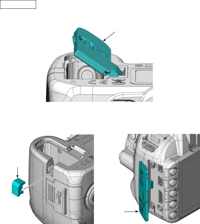
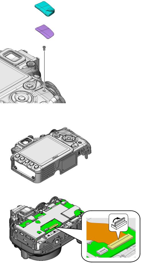
Rear cover unit
• Incline the battery cover unit (#B151) at an approx. 35° as below, and remove it.
#B151
•Remove the power connector cover (#72).
•Remove the IF cover (#71).
#72
#71
- D2 D3100 -
User ID:INC
VBA28001-R.3813.A
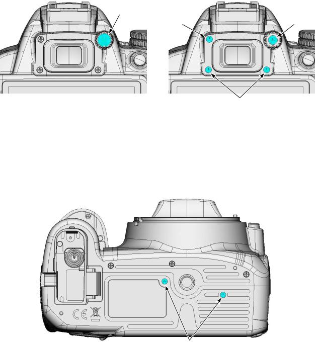
•Remove the cover (#267).
•Take out the screw (#614).
•Take out the two screws (#623).
•Take out the screw (#634).
#267
#634 |
#614 |
#623
• Take out the two screws (#631).
#631
- D3 D3100 -
User ID:INC
VBA28001-R.3813.A
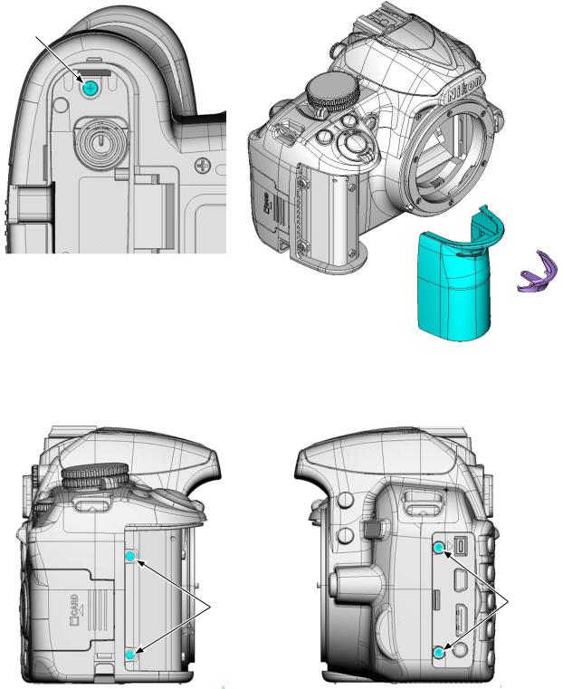
•Take out the screw (#661).
•Remove the grip unit (#B26). Do NOT reuse the grip unit that was once removed.
•Remove the grip cover (#27).
#661
#27
#B26
•Take out the two screws (#640).
•Take out the two screws (#623).
#640 |
#623 |
|
- D4 D3100 -
User ID:INC
VBA28001-R.3813.A
•Remove the rubber (#410) and double-stick tape (#411).
•Take out the screw (#622).
#410
#411
#622
•Lift up the rear cover unit.
•Disconnect the FPC.
•Remove the rear cover unit.
- D5 D3100 -
User ID:INC
VBA28001-R.3813.A
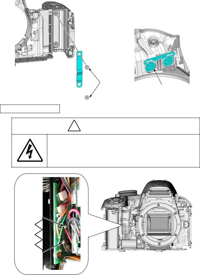
Front cover unit
•Take out the two screws (#644) and one screw (#639).
•Take out the three screws (#631).
•Take out the one screw (#643) and two screws (#634).
#639
#644
#644 |
#631 |
#634
#643
• Slacken the tripod base area, and remove the front cover unit.
- D6 D3100 -
User ID:INC
VBA28001-R.3813.A
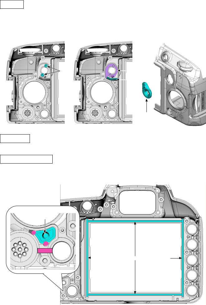
•Take out the two screws (#646) from the front cover (#24).
•Remove the spring (#160).
•Remove the button (#465).
#24
#160
#646
#465
Discharge of main condenser
! WARNING
 There are high voltage parts inside. Be careful of this electric shock, when you remove the cover.
 You must discharge the main condenser according to the instruction of this repair manual after you remove the cover.
2KΩ/5W
- D7 D3100 -
User ID:INC
VBA28001-R.3813.A
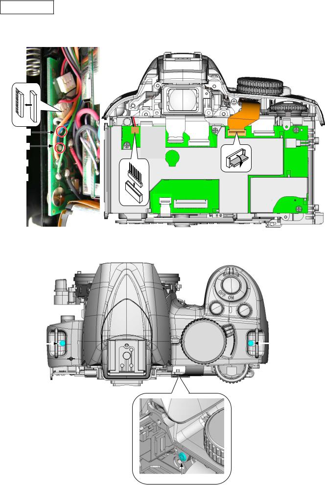
Top cover unit
•Unsolder the four wires of the SB lower cover unit.
•Remove the harness and FPC.
[Gray]
[Blue]
[Orange]
 [Green]

•Take out the screws (#631, #632, and #656).
•Remove the top cover.
#631 |
|
|
|
#632 |
|
|
#656
- D8 D3100 -
User ID:INC
VBA28001-R.3813.A
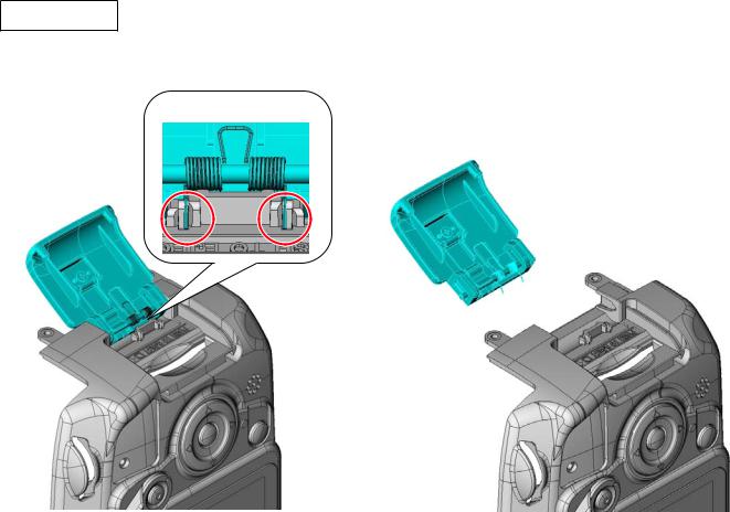
2. Rear Cover
SD cover unit
• Remove the SD cover unit (#B431) from the rear cover unit.
 Unhook.
#B431
- D9 D3100 -
User ID:INC
VBA28001-R.3813.A
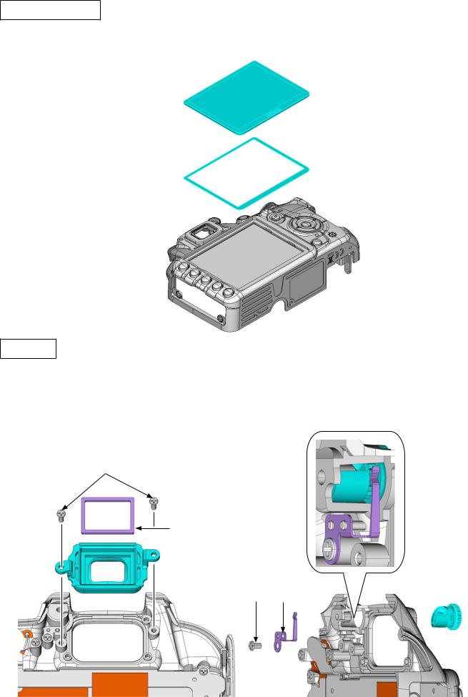
LCD monitor cover
•Remove the LCD monitor cover (#402).
•Peel off the double-stick tape (#403).
#402
#403
Eyepiece
•Take out the two screws (#624), and remove the eyepiece frame unit from the rear cover.
•Remove the sponge (#476) from the eyepiece frame (#475).
•Take out the screw (#621).
•Remove the retainer plate (#266).
•Remove the diopter adj. knob (#265).
#624
#476

 #475
#475
#621 |
#266 |
#265 |
- D10 D3100 -
User ID:INC
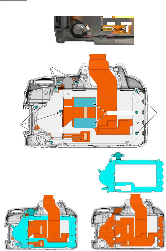
Retainer plate
•Unsolder the two wires of the speaker (#1054).
•Peel off the two pieces of the tape [TA-0005 (10×20)].
•Take out the nine screws (#621).
•Remove the retainer plate (#406).
#621
#621
- D11 D3100 -
VBA28001-R.3813.A
[Red] [Black]
TA-0005 (10x20)x2  #621
#621
#406
User ID:INC
VBA28001-R.3813.A
Speaker
• Remove the speaker (#1054).
#1054
Rear FPC
•Disconnect the two FPCs.
•While slacking the FPC (see below) of the LCD monitor (#1049), remove the rear FPC unit (#B1016).
#1049 #B1016
- D12 D3100 -
User ID:INC
VBA28001-R.3813.A
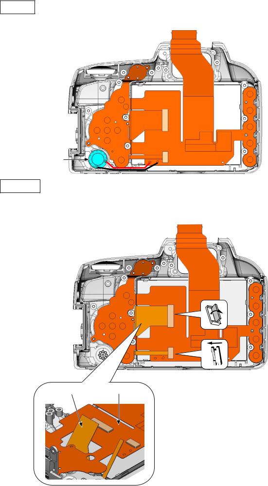
LCD monitor
• Remove the LCD monitor (#1049).
#1049
Rear button
#424
#425
#385
#416 #386
#412
#415
#413
- D13 D3100 -
User ID:INC
VBA28001-R.3813.A
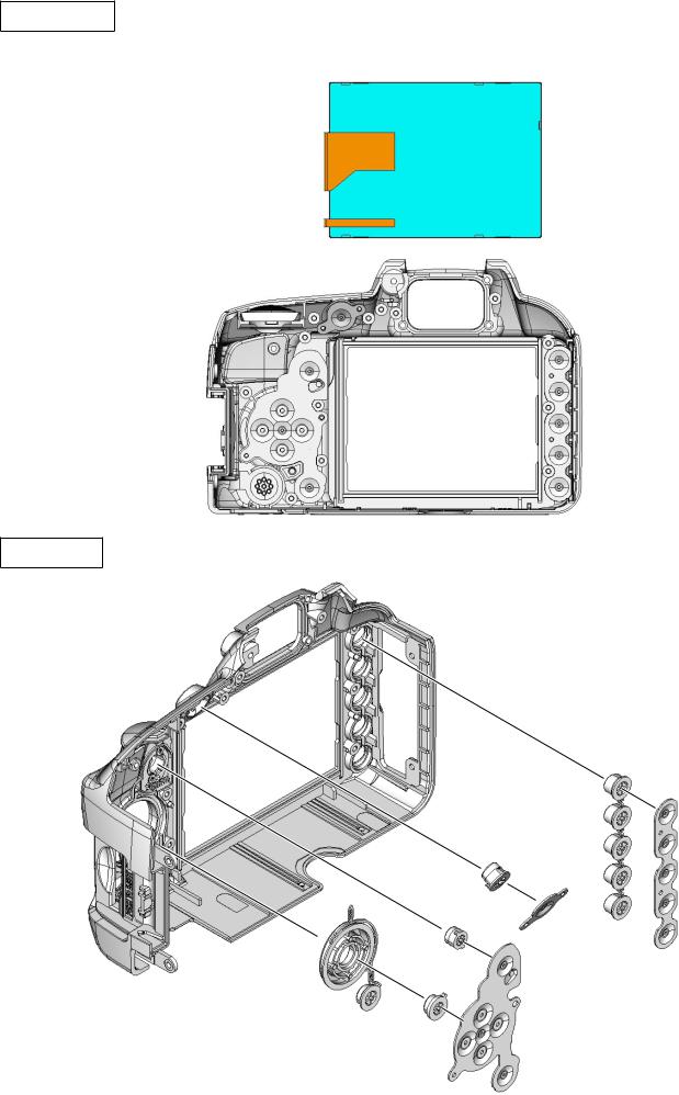
LV lever
•Take out the two screws (#619).
•Remove the retainer plate (#471), spring (#472), and LV lever (#470).
#619 |
|
|
#471 |
|
|
||||
|
|
|
#472 |
|
|
|
|
||
#470
TFT sponge
•Remove the two sponges (#404) and two sponges (#405). SD access lamp window
•Remove the adhesive (EDC0021), then remove the SD access lamp window (#408).
#408
EDC0021
|
#405 |
|
#405 |
|
#404 |
||
|
- D14 D3100 -
User ID:INC
VBA28001-R.3813.A
3. Top Cover
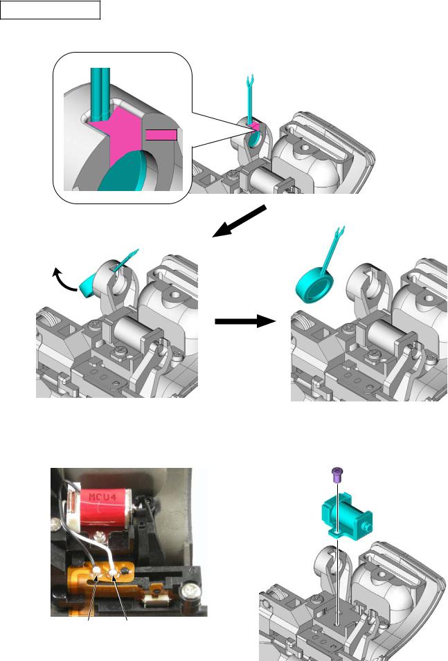
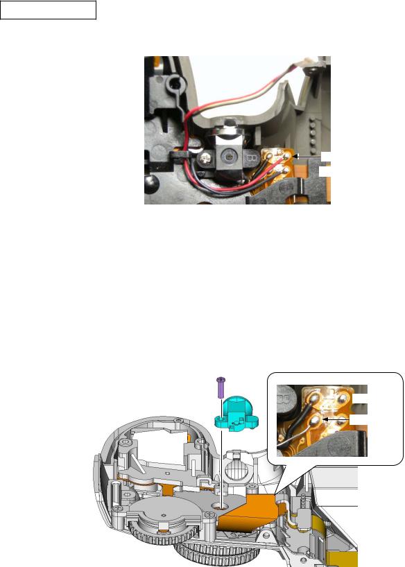
SB release PCB unit
• Remove the "Super X" (C-8008B), then remove the microphone (#1053).

 C-8008B
#1053
•Unsolder the two wires.
•Take out the screw (#618), and remove the driving magnet (#36).
#618
#36
[Black] [White]
- D15 D3100 -
User ID:INC
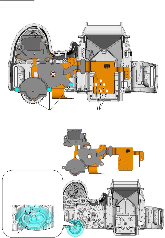
•Take out the three screws (#617).
•Unhook the top cover FPC unit (#B1007) in the numeric order from to , and then remove the SB release PCB (#455).
#617
#455
#B1007
•Remove the SB release lever (#456).
•Remove the SB lock lever (#309) and spring (#458) together.
•Remove the spring (#458) from the SB lock lever (#309).
#456
 #458
#458
#309
#309 #458
#458
- D16 D3100 -
User ID:INC
VBA28001-R.3813.A
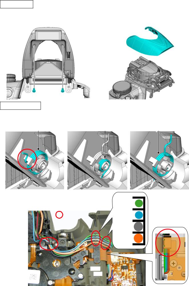
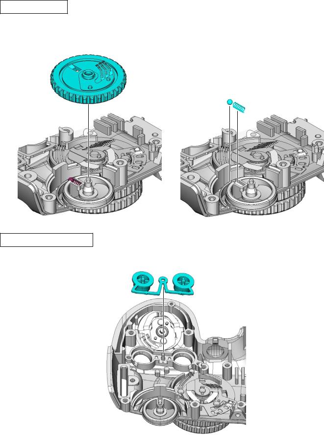
SB upper cover
•Take out the two screws (#628).
•Remove the SB upper cover (#301).
#301
 #628
#628
SB lower cover unit
•Unhook the spring (#305).
•Unhook the spring (#459) and spring (#305).
|
#459 |
#305 |
#305 |
• Unsolder the two wires. |
|
• Release the four wires from the four guides. |
[Green] |
|
|
Guide |
[Blue] |
|
[Gray] |
|
[Orange] |
[Blue] [Red]
[Red]
- D17 D3100 -
User ID:INC
VBA28001-R.3813.A
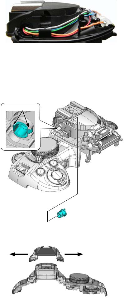
• Pull out the wires.
• Remove the roller (#308) while releasing the hooks.
Release hooks.
#308
• Remove the SB lower cover unit (#B302).
#B302
- D18 D3100 -
User ID:INC
VBA28001-R.3813.A
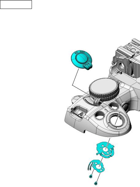
AF assist lamp unit
• Unsolder the two wires of the harness (#1027).
#1027 
[Red]
 [Black]
•Unsolder the two wires of the AF assist lamp unit (#B325).
•Take out the screw (#629), and remove the AF assist lamp unit (#B325).
#629
 [Black]
#B325 |
[Uncoated] |
|
- D19 D3100 -
User ID:INC
VBA28001-R.3813.A
Top cover FPC unit
•Remove the five solders of the hot shoe.
•Take out the three screws (#617).
#617
• Remove the top cover FPC unit (#B1007).
Caution: When the top cover FPC unit is removed, be careful that the inner click spring (#361) and click ball (#362) in the command dial may
pop out.
#362 #361
#B360
- D20 D3100 -
Solder×5
#B1007
User ID:INC
VBA28001-R.3813.A
Command dial unit
•Remove the command dial unit (#B360).
•Remove the click ball (#362) and click spring (#361).
#B360
#362
#361
Info & "+ -" aperture button
• Remove the button (#381).
#381
- D21 D3100 -
User ID:INC
VBA28001-R.3813.A
ON-OFF dial
•Take out the two screws (#615).
•Remove the ON-OFF SW brush (#348) and ON-OFF click plate (#347).
•Remove the power dial unit (#B345).
#B345
#347
#348
#615
- D22 D3100 -
User ID:INC

VBA28001-R.3813.A
Mode dial unit
•Take out the screw (#616).
•Remove the contact brush (#372) and click spring (#373).
•Remove the mode dial unit (#B371).
Unhook. |
#616 |
#372
#373
#B371
•Take out the two screws (#663).
•Remove the contact brush (#375), click ball (#362), and release mode dial (#374).
#663
#375
#362
[#362] close-up
#374
- D23 D3100 -
User ID:INC
VBA28001-R.3813.A
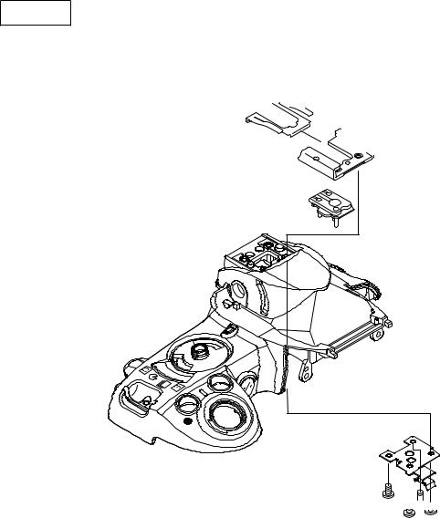
Hot shoe
•Take out the four screws (#627).
•Remove the holder plate (#322), hot shoe spring (#318), hot shoe (#316), and hot shoe mold unit (#B317).


 #318
#318


 #316
#316
#B317
#322


 #627
#627
- D24 D3100 -
User ID:INC
VBA28001-R.3813.A
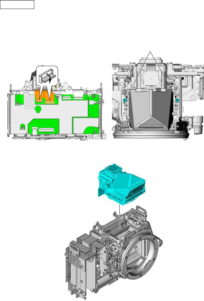
Prism box unit
Note:The prism box unit can be disassembled until the stage shown from page D26 to D28, Further disassembly can not be made. (ref. parts list)
•Disconnect the two FPCs.
•Take out the two screws (#613).
#613
• Remove the prism box unit.
- D25 D3100 -
User ID:INC
 Loading...