


M317E 04.2.CF.2(1/2)
Microscope
ECLIPSE 50i
ECLIPSE 55i
Instructions

Introduction
Thank you for purchasing this Nikon product.
This instruction manual is intended for users of the Nikon ECLIPSE 50i and 55i microscopes. To ensure correct use, please read this manual carefully before operating the product.
•This manual may not be reproduced or transmitted in whole or in part without Nikon's express consent.
•The contents of this manual are subject to change without notice.
•Although every effort has been made to ensure the accuracy of this manual, errors or inconsistencies may remain. If you note any points that are unclear or incorrect, please contact your nearest Nikon representative.
•Some of the products described in this manual may not be included in the set you have purchased.
•Make sure you have read the manuals for any other products attached to or to be used with this product (super high-pressure mercury lamp power supply, high-intensity light source, etc.).
Warning/Caution symbols used in this manual
Although Nikon products are designed to provide the utmost safety, ignoring safety precautions or improper use may result in personal injury or property damage, as well as voiding the terms of the warranty. To ensure safe use, please read the instruction manual carefully and thoroughly before trying to operate the instrument. Do not discard this manual. Store in a convenient location near the product for ready reference.
In this manual, safety precautions are indicated by the following symbols. For safe, correct use of the product, always follow the instructions indicated by these symbols.
Symbol |
Meaning |
|
|
Disregarding instructions indicated by this symbol may result in death or serious
WARNING injury.
Disregarding instructions indicated by this symbol may result in injury or property
CAUTION damage.
1
Introduction
Meaning of symbols used on the product
When appearing on the product, the symbols below indicate the need for caution at all times during use.
Consult the instruction manual and read the relevant instructions before attempting to use or adjust any part to which the symbol has been affixed.
Caution! Biohazard
This symbol found on the stage indicates the following:
•WARNING: Contact between sample and the product may result in biohazard risks.
•To avoid biohazard contamination, avoid touching the contaminated portion with bare hands..
•Decontaminate the contaminated part according to the standard procedure specified for your laboratory.
Caution for heat
This symbol found on the lamphouse of the ECLIPSE 50i indicates the following:
•The lamp and surrounding areas (including the lamphouse) become very hot during and immediately after a period of illumination.
•Risk of burns. Do not touch the lamp or surrounding areas during or immediately after a period of illumination.
•Make sure the lamp and surrounding areas have cooled sufficiently before attempting to replace the lamp
Caution
This symbol found on the wiring cover of the ECLIPSE 55i indicates the following:
•Always connect the specified battery and cables to the appropriate terminals. Failure to do so may result in malfunction.
•Do not remove the wiring cover.
Do not remove the cover except for when assembling the product or replacing batteries. Using the system without the cover may cause a short, resulting in abnormal heat. Always use the product with the wiring cover on.
2

Safety Precautions
Please follow the safety precautions given below.

 WARNING
1.Intended use of the product
This product is intended primarily for microscopic observations and image capture of cells and tissue set on glass slides using diascopic (transmitted) and episcopic (reflected) illumination.
It is intended for use in experimentation and observation of cells and tissue in the fields of pathology and cytology in hospital and other laboratory settings.
2.Do not disassemble.
Disassembly may result in malfunctions and/or electrical shock and will void the terms of the warranty. Never attempt to disassemble any part other than the parts described in this manual. If you experience problems with the product, contact your nearest Nikon representative.
3.Read the instruction manuals carefully.
To ensure safety, carefully read this manual and the manual provided with any other equipment used with this product. Observe all warnings and cautions given at the beginning of each manual.
When the J-FL 50i55i Epi-fluorescence attachment is mounted on the product:
The mercury lamp (or xenon lamp) for Epi-fl microscopy requires special care during handling. Make sure you have read the instruction manual for the light source (super high-pressure mercury lamp power supply or high-intensity light source).
4.Power cord for ECLIPSE 50i and the power cord for AC adapter
Use one of the power cords specified. Using the wrong power cord may result in fire or other hazards. The product is classified as subject to Class I protection against electrical shock. Make sure it is connected to an appropriate ground terminal.
Refer to Chapter 8 for the power cords specified.
To prevent electric shock, always turn off the main power switch (press it to the "{" position) of the product before attaching or detaching the power cord.
5.Use the specified AC adapter (when using the ECLIPSE 55i) (when using J-CY cytodiagnostic unit).
The ECLIPSE 55i and the J-CY cytodiagnostic unit are powered by an AC adapter. Use only the specified adapter model meeting the requirements. Using any other type of adapter may result in malfunction, overheating, and/or fire.
Refer to Chapter 8 for the adapter specified.
•To prevent malfunctions and/or fire, use the AC adapter in a well-ventilated location. To ensure proper heat radiation and to prevent overheating, never cover or place any object on the adapter.
•To prevent malfunctions, always turn off the power switch (press it to the "{" position) of the product before attaching the AC adapter.
3

Safety Precautions

 WARNING
6.Heat from the light source (when using the ECLIPSE 50i)
The lamp and surrounding areas (including the lamphouse) will become very hot during and immediately after a period of illumination.
•Risk of burns. Never touch the lamp or surrounding areas during or immediately after a period of illumination
•Always attach the lamphouse cover when using the product.
•Make sure the lamp and surrounding areas have cooled sufficiently before attempting to replace the lamp
•To avoid risk of fire, do not place fabric, paper or highly flammable volatile materials such as gasoline, petroleum benzine, paint thinner or alcohol near the lamphouse while the lamp is lit or during a period of around thirty minutes after the lamp has been turned off.
7.Mercury lamps and xenon lamps (when the J-FL 50i55i Epi-fluorescence attachment is attached)
The mercury lamp (or xenon lamp) used for J-FL 50i55i Epi-fluorescence attachment requires special care during handling. For safe and correct use of this system, carefully read the warnings below. Keep in mind all potential hazards. Additionally, carefully read the manual for the super high-pressure mercury lamp power supply (or high-intensity light source) and the manual (if provided) from the lamp manufacturer, then follow the instructions given therein.
Hazards of mercury lamps and xenon lamps
1)When lit, mercury (and xenon) lamps radiate ultraviolet light that can damage the eyes and skin. Direct viewing of the light may result in blindness.
2)The lamps contain sealed gas under very high pressure, pressure that increases when the lamp is on. If the lamp is scratched, fouled, subjected to high external pressure or physical impact, or used beyond its service life, the sealed gas may escape or the lamp may burst, resulting in gas inhalation, injury from glass, or other injury.
3)When the lamp is lit, the lamp and surroundings will become extremely hot. Touching the lamp with bare hands may result in burns; flammable materials placed near the lamp may ignite.
4)Using the wrong lamp type may result in accidents, including bursting of the lamp.
Safety is a top design priority for Nikon products. The preceding hazards should pose no danger as long as the user observes all of the warnings and cautions given in the manuals, and uses the system only for its intended purpose.
However, failure to heed the warnings and cautions given in the manuals, subjecting the system to shock or impact, or attempting to disassemble the system may result in accidents and injury. Make sure you are familiar with and adhere to all warnings and cautions.
8.Always turn off the lamp when changing filter cubes
(when the J-FL 50i55i Epi-fluorescence attachment is attached to the product).
When changing filter cubes, always turn off the light source of the Epi-fl attachment. Leaving the lamp on may result in ultraviolet exposure.
9.Hazardous sample
This product is intended primarily for microscopic observations and image capture of cells and tissue set on glass slides.
Check to determine whether a sample is hazardous before handling.
Handle hazardous samples according to the standard procedure specified for your laboratory. If the sample is potentially infectious, wear rubber gloves and avoid touching samples. If contact occurs between a sample and the product, decontaminate the contaminated portion according to the standard procedure specified for your laboratory.
4

Safety Precautions

 CAUTION
1.Isolate the products from the power source during assembly, connection/disconnection of cords, lamp replacement, and maintenance.
To prevent electric shock and/or malfunctions, always turn off the power switch(es) of the product (press to the "{" position) and unplug the power cord from the wall outlet before assembly, connecting or disconnecting of cords, lamp replacement, and cleaning of the product and the objective.
2.Lamp replacement precautions (when using the ECLIPSE 50i)
To avoid burns, wait at least 30 minutes after the lamp is turned off to give it sufficient time to cool. To avoid electric shock or malfunctions, never attempt to replace the lamp without first turning off the power switches for the product and the peripheral devices (press them to the "{" position) and unplugging the power cord from the wall outlet.
Make sure the lamphouse cover is securely fitted to the lamphouse after lamp replacement. Never turn on the lamp while the lamphouse cover is open. Do not break up used lamps; instead, dispose of them as special industrial waste or as specified by local regulations.
3.Use the specified lamp (when using the ECLIPSE 50i).
The product's built-in power source is used for the halogen lamp that is a light source for the diascopic illumination. A halogen lamp up to 6V-30W can be lit. Always use the specified halogen lamp. Using an unspecified lamp may cause malfunctions.
Specified lamp: 6V-30W (PHILIPS 5761)
4.Avoid contact with water.
Never allow water to come into contact with the product, and keep the product away from liquids. Splashing water onto the product may cause a short, resulting in malfunction or abnormal heating. If water is splashed onto the product, immediately turn off the power switch (press to the "{" position) and remove the power cord from the receptacle. Then wipe off moisture with a dry cloth or something similar. If water enters the product, do not use; in this case, contact your nearest Nikon representative.
5.Do not place any object on top of the product.
Do not place any object on top of the product or cover it with a cloth or the like. The system temperature will rise, resulting in malfunctions.
5

Safety Precautions

 CAUTION
6.Cautions on assembling, installing, and carrying the product
•Take care to avoid pinching your fingers or hands during product assembly.
•Scratches or fouling such as fingerprints on optical components (such as lens and filters) will degrade microscope images. Be careful to avoid scratches or direct contact with the lens and filters.
•The main unit weighs about 9 kg. Grasp the main unit by the handle on the back of the product and the recess at the base on the opposite side from the handle.
•Remove all attachments (if mounted) from the microscope before carrying the microscope.
•Do not install the product in a locker or cabinet.
7.Operating, transporting, and storage conditions
The product must be operated, transported, or stored under the following conditions. Using or storing the product in hot, humid locations may result in mildew formation or condensation on lenses, imparing performance or generating malfunction.
•Operating conditions: temperature (0 to 40°C), humidity (85% RH max., no condensation)
•Transporting/storage conditions: temperature (-20 to +60°C), humidity (90% RH max., no condensation)
8.Use the product with the wiring cover (when using the ECLIPSE 55i).
Do not remove the wiring cover except when assembling the product or replacing batteries. Using the system without the wiring cover may cause a short, resulting in abnormal heat.
9.Remove any covers from the product before switching on.
Do not use the product while covered with a cloth, etc., as this will result in abnormal heat and fire hazards.
10.Caution concerning long, sustained observations
To relieve fatigue resulting from long observation sessions, limit continuous observations to one hour. Take at least 10to 15-minute breaks between observation sessions. Adjust the layout of other equipment and the height of your chair.
11.Disposal of the product
To avoid biohazard risks, dispose of the product as contaminated equipment according to the standard procedure specified for your laboratory.
6

Safety Precautions

 CAUTION
12.Rechargeable battery (when using the ECLIPSE 55i)
Use the Nikon EN-EL1 Li-ion rechargeable battery for the ECLIPSE 55i. Do not use any other type of battery. Although the EN-EL1 is designed for use with Nikon digital cameras, it can also be used for the ECLIPSE 55i.
Take the following precautions when handling the battery:
•Do not expose to open flames or excessive heat. The battery may become hot, leak, or burst.
•Do not short circuit or disassemble.
The battery may become hot, leak, or burst.
•Always use the charger specified (e.g., MH-53).
If a different charger is used, the battery may become hot, leak, or burst.
•The EN-EL1 is designed specifically for Nikon digital cameras and the ECLIPSE 55i. Do not use it for any other equipment.
The battery may become hot or leak.
•Do not carry or store with metallic objects such as necklaces or hairpins. The battery may become hot, leak, or burst.
•Do not expose to direct sunlight, or leave inside a sun-heated car with all windows shut. The battery may become hot, leak, or burst.
•Do not drop or expose to strong impact. The battery may become hot, leak, or burst.
•Keep out of reach of small children.
The battery can be swallowed by small children. If swallowed, consult a physician immediately.
•Do not immerse in water or allow to become wet. The battery may become hot or leak.
•Do not use if unusual features, such as discoloration or deformation, are present. The battery may become hot or leak.
•Do not exceed the charging period, even if battery is not fully charged. The battery may become hot or leak.
•Insulate the contacts with tape, etc., when disposing of the battery.
The battery may become hot, burst, or ignite on contact with other metals.
•Observe local waste disposal regulations upon disposal.
•Please read the instruction manuals supplied with the EN-EL1 and the battery charger.
7

Notes on handling the product
Notes on handling the product
1.Handle the product gently.
This product is a precision optical instrument and requires gentle handling. Avoid subjecting it to sudden impact and shocks.
Even relatively minor impacts are capable of affecting the precision of the objective.
2.Weak electromagnetic waves
The product emits weak electromagnetic waves. Do not install the product near precision electronic devices to avoid degrading their performance. If the TV or radio reception is affected, move the TV or radio farther from the product.
3.Scratches, dirt, and foreign particles on the lens
Scratches or fouling such as fingerprints on optical components (such as lens and filters) will degrade microscope images. If these parts become dirty, clean them as described in chapter "7. Care and maintenance" at the end of this manual.
4.Dirt on the lamps (when using the ECLIPSE 50i)
Never touch the lamp with bare hands. Dirt or fingerprints on the lamp will result in uneven illumination and reduce the service life of the lamp. Always wear gloves when handling lamps.
5.Installation location
This product is a precision instrument. Use or storage in inappropriate environments may result in malfunctions or poor performance. Consider the following factors when selecting an installation location:
•Select a vibration-free location. Install the product on a level surface.
•Install the product at least 10 cm away from walls.
•Choose a location less exposed to hazards in the event of collisions, earthquakes, or other potential disasters. To keep the product from falling, use strong rope or other means if necessary to secure it to the working desk or to another heavy, stable item.
•Avoid locations exposed to direct sunlight, locations immediately under room lights, and other bright locations.
•Avoid locations with excessive dust.
•To avoid splashes, do not use the product near water.
•Make sure the ambient temperature is 0 to 40°C and humidity is 85% or less. Installing the product in hot, humid locations may result in mildew formation or condensation, impairing performance or generating malfunctions.
•Storage conditions for transportation are as follows: temperature (-20°C to +60°C), humidity (90% RH max., no condensation)
•Do not install the product in a locker or cabinet.
•Select a layout that allows easy removal of the power cord from the product's AC inlet in the event of an emergency.
•Room lights just above the product may enter the objective as extraneous light. If possible, switch off room lights directly above the product when making observations.
•Do not use on a desk mat or the like.
8
Notes on handling the product
6.Focusing knobs
•Never turn the focus knobs on the left and right sides of the product in opposite directions at the same time. Doing so may damage the product.
•Turning the coarse focus knob past its farthest point will damage the product. Never use undue force when turning the knob.
7.Protect the ports from dust and extraneous light (when the trinocular eyepiece tube or the C-TE ergonomic binocular tube is attached).
To keep out extraneous light and dust, always attach the supplied cap to any port not currently in use.
8.Handling of filters (when J-FL 50i55i Epi-fluorescence attachment is attached to the product)
•Interference filters (especially excitation filters, which are exposed to strong light) degrade over time. Replace them after the appropriate number of hours.
•Filter characteristics may alter if the filter is exposed to high humidity. To prevent changes in or degradation of filter characteristics, avoid using or storing the filters under conditions of high humidity or high temperature. Avoid subjecting filters to rapid temperature changes. When a filter is not in use, store in a desiccator or hermetically sealed container with a drying agent.
•The filters in the nine types of filter cubes listed below offer sharp, high-resolution waveform characteristics superior to normal filters. However, due to their sophisticated coatings, they must be handled with special care. In particular, take care to avoid abrasion from cleaning. (Follow the procedure described in section "1. Filter and lens cleaning" of chapter "7. Care and Maintenance.") Single-band filter cubes: DAPI, FITC, TxRed, GFP
Multi-band filter cubes: F-R, F-T, D-F, D-F-R, D-F-T
9

Abbreviations Used in This Manual
Abbreviations Used in This Manual
The product names and abbreviations used in this manual are given below.
The manual uses the following abbreviations:
Name of device |
Abbreviation |
|
|
Microscope ECLIPSE 50i |
50i |
|
|
Microscope ECLIPSE 55i |
55i |
|
|
C-ER Eye Level Riser |
Eye Level Riser |
|
|
C-TE Ergonomic Binocular Tube |
Ergonomic Binocular Tube |
|
|
C-TEP DSC Port for Ergonomic Binocular Tube |
DSC Port |
|
|
J-FL 50i55i Epi-Fluorescence Attachment |
Epi-fl Attachment |
|
|
J-CY Cytodiagnostic Unit |
Cytodiagnostic Unit |
|
|
C-HS Hand switch |
Hand Switch |
|
|
DS Camera Head DS-5M |
Camera Head |
|
|
DS Camera Control Unit DS-L1 |
DS-L1 |
|
|
DS Camera Cable |
Camera Cable |
|
|
Super High Pressure Mercury Lamp Power Supply |
Mercury Lamp Power Supply |
|
|
Super High Pressure Mercury Lamphouse |
Mercury Lamphouse |
|
|
10

Contents
Contents
Introduction |
....................................................................................................... |
|
1 |
Warning/Caution symbols used in this manual .................................................................. |
1 |
||
Meaning of symbols used on the product ......................................................................... |
2 |
||
Safety Precautions .............................................................................................. |
|
3 |
|
WARNING.................................................................................................... |
|
3 |
|
CAUTION..................................................................................................... |
|
5 |
|
Notes on handling the product .............................................................................. |
8 |
||
Abbreviations Used in This Manual........................................................................ |
10 |
||
Chapter 1 Part Names......................................................................................... |
14 |
||
1.1 |
Names of Main Components ............................................................................... |
14 |
|
1.2 |
Names of Parts Used to Make Adjustments........................................................... |
15 |
|
|
1.2.1 |
Right view ................................................................................................ |
15 |
|
1.2.2 |
Left view .................................................................................................. |
16 |
|
1.2.3 |
Rear view (50i).......................................................................................... |
17 |
|
1.2.4 |
Rear view (55i).......................................................................................... |
18 |
|
1.2.5 Ergonomic binocular tube with camera attached ............................................ |
19 |
|
|
1.2.6 With cytodiagnostic unit attached ................................................................ |
20 |
|
|
1.2.7 With Epi-fl attachment mounted .................................................................. |
21 |
|
Chapter 2 Microscopy ......................................................................................... |
22 |
||
2.1 |
Bright-Field Microscopy...................................................................................... |
22 |
|
2.2 |
Microscopy with Cytodiagnostic Unit Attached....................................................... |
26 |
|
2.3 |
Microscopy with Epi-fl Attachment Mounted.......................................................... |
29 |
|
2.4 |
Photomicroscopy............................................................................................... |
32 |
|
Chapter 3 Individual Operations ........................................................................... |
34 |
||
3.1 |
Power ON/OFF .................................................................................................. |
35 |
|
|
3.1.1 |
Microscope................................................................................................ |
35 |
|
3.1.2 |
Cytodiagnostic unit .................................................................................... |
35 |
|
3.1.3 Light source of the Epi-fl attachment (mercury lamp)..................................... |
35 |
|
3.2 |
Brightness Adjustment....................................................................................... |
36 |
|
|
3.2.1 Adjustment using the brightness control knob ............................................... |
36 |
|
|
3.2.2 Adjustment using the preset switch ............................................................. |
37 |
|
|
3.2.3 Adjustment with the ND filter IN/OUT lever (for 50i) ...................................... |
37 |
|
3.2.4Automatic adjustment after magnification change
|
|
(only for a 55i when a cytodiagnostic unit is attached) ................................... |
38 |
|
3.2.5 Adjustment with the ND filter of the Epi-fl attachment.................................... |
38 |
|
|
3.2.6 Transmitted image in fluorescence observation.............................................. |
38 |
|
|
3.2.7 Camera adjustment (adjusting the brightness of the image on the monitor)...... |
39 |
|
3.3 |
Optical Path Switching ....................................................................................... |
39 |
|
|
3.3.1 |
Optical path distribution ............................................................................. |
39 |
|
3.3.2 Disabling the clicking of the optical path switching lever ................................. |
39 |
|
3.4 |
Vertical Stage Motion......................................................................................... |
40 |
|
|
3.4.1 |
Prohibited actions ...................................................................................... |
40 |
|
3.4.2 Knob rotation direction and stage motion direction ........................................ |
40 |
|
|
3.4.3 Number of knob turns and distance of stage travel ........................................ |
40 |
|
11

Contents
3.4.4 |
Adjusting the rotating torque of the coarse focus knob ................................... |
41 |
|
3.4.5 |
How to refocus .......................................................................................... |
41 |
|
3.5 |
XY Stage Motion ............................................................................................... |
42 |
|
3.5.1 |
Prohibited action........................................................................................ |
42 |
|
3.5.2 |
Knob rotation direction and stage motion direction ........................................ |
42 |
|
3.5.3 |
Adjusting the knob heights ......................................................................... |
42 |
|
3.5.4 |
Adjusting the knob rotation torque............................................................... |
42 |
|
3.6 |
Diopter Adjustment ........................................................................................... |
43 |
|
3.7 |
Interpupillary Adjustment .................................................................................. |
44 |
|
3.8 |
Adjusting the Observation Position ...................................................................... |
44 |
|
3.9 |
Adjusting the Condenser Position ........................................................................ |
45 |
|
3.10 |
Adjusting the Aperture Diaphragm ...................................................................... |
46 |
|
3.10.1 |
Adjusting the aperture diaphragm opening using the condenser scale .............. |
46 |
|
3.10.2Adjusting the aperture diaphragm opening using the centering telescope
|
|
(optional) ................................................................................................. |
46 |
3.11 |
Selecting a Condenser ....................................................................................... |
47 |
|
3.12 |
Adjusting the Field Diaphragm ............................................................................ |
47 |
|
3.13 |
Oil Immersion Operation .................................................................................... |
48 |
|
3.14 |
Water Immersion .............................................................................................. |
49 |
|
3.15 |
Using the Cytodiagnostic Unit ............................................................................. |
50 |
|
3.15.1 |
Magnification switching............................................................................... |
50 |
|
3.15.2 |
Marking specimens .................................................................................... |
50 |
|
3.16 |
Fluorescence Observation................................................................................... |
51 |
|
3.16.1 |
Warning.................................................................................................... |
51 |
|
3.16.2 Shutter of the Epi-fl attachment .................................................................. |
51 |
||
3.16.3 Light shielding plate of the Epi-fl attachment................................................. |
51 |
||
3.16.4 Field diaphragm of the Epi-fl attachment ...................................................... |
51 |
||
3.16.5 |
Switching excitation methods ...................................................................... |
52 |
|
3.16.6 Inserting and removing the filter cubes ........................................................ |
52 |
||
3.16.7 ND filters of the Epi-fl attachment................................................................ |
53 |
||
3.17 |
Selecting Fluorescent Filters ............................................................................... |
54 |
|
3.17.1 Selecting excitation filters (EX filters)........................................................... |
55 |
||
3.17.2 Selection of barrier filter (BA filter) .............................................................. |
55 |
||
3.17.3 Replacing excitation and barrier filters.......................................................... |
57 |
||
3.17.4 |
Filter cube internal spacers ......................................................................... |
57 |
|
3.18 |
Image Capture ................................................................................................. |
58 |
|
3.18.1 |
Adjusting light intensity.............................................................................. |
58 |
|
3.18.2 |
Adjusting the condenser ............................................................................. |
58 |
|
3.18.3 Confirming the photomicrographic range ...................................................... |
58 |
||
3.18.4 |
Confirming focus ....................................................................................... |
58 |
|
3.18.5 Making adjustments to keep out extraneous light .......................................... |
59 |
||
3.18.6 |
Anti-vibration measures.............................................................................. |
59 |
|
3.18.7 |
Fluorescence photomicrography................................................................... |
59 |
|
Chapter 4 Assembly ........................................................................................... |
60 |
||
Chapter 5 Replacing Consumables ........................................................................ |
71 |
||
5.1 Replacing the lamp (for the 50i).......................................................................... |
71 |
||
5.2 Recharging the battery (for the 55i) .................................................................... |
72 |
||
12

Contents
5.3 |
Refilling Cytodiagnostic Unit Ink.......................................................................... |
73 |
Chapter 6 Troubleshooting................................................................................... |
74 |
|
6.1 |
Optical............................................................................................................. |
74 |
6.2 |
Operational ...................................................................................................... |
75 |
6.3 |
Electrical.......................................................................................................... |
75 |
Chapter 7 Care and Maintenance.......................................................................... |
76 |
|
7.1 |
Lens Cleaning ................................................................................................... |
76 |
7.2 |
Cleaning the Product ......................................................................................... |
76 |
7.3 |
Disinfecting the Product ..................................................................................... |
76 |
7.4 |
Storage............................................................................................................ |
77 |
7.5 |
Periodic Inspections (fee charged)....................................................................... |
77 |
Chapter 8 Technical Specifications ........................................................................ |
78 |
|
8.1 |
Specifications ................................................................................................... |
78 |
13
1 Part Names
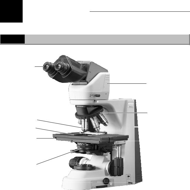
1.1Names of Main Components
Eyepiece
Eyepiece tube
Revolving nosepiece
Objective
Specimen holder |
|
Microscope (main body) |
|
Stage
Condenser
14
Chapter 1 Part Names
1.2Names of Parts Used to Make Adjustments
1
1.2Names of Parts Used to Make Adjustments
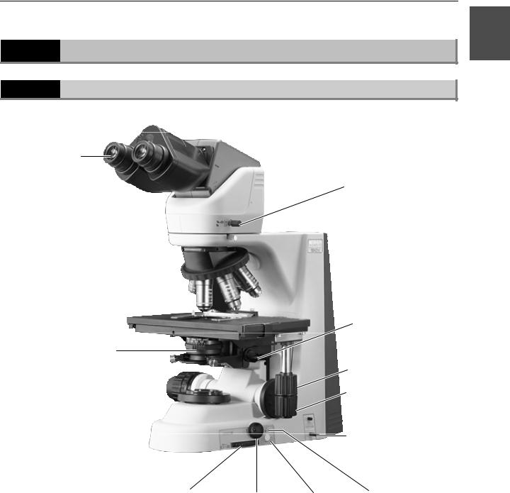
1.2.1Right view
Diopter adjustment ring
Aperture diaphragm knob
Optical path switching lever
Refocusing lever
Y stage knob
X stage knob
50i:
ND filter IN/OUT lever 55i:
Color compensating filter IN/OUT lever
Field diaphragm |
Brightness |
Preset |
Preset brightness |
knob |
control knob |
switch |
control knob |
15
Chapter 1 Part Names
1.2Names of Parts Used to Make Adjustments
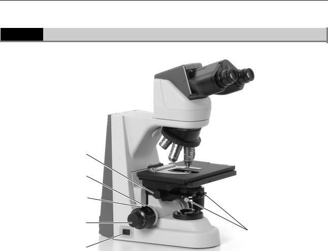
1.2.2Left view
Condenser focus knob
Coarse focus torque adjustment knob
Coarse focus knob
Fine focus knob
Condenser centering screws
Power switch
16
Chapter 1 Part Names
1.2Names of Parts Used to Make Adjustments
1
1.2.3Rear view (50i)
Handle |
|
|
|
|
|
|
|
|
|
|
|
|
|
|
|
|
|
|
|
|
|
Wiring guides |
|
|
|
|
|
|
|
|
Wiring guides |
|
|
|
|
|
|
|
|
|
|||
|
|
|
|
|
|
|
|
|
|
|
Input voltage indication |
|
|
|
|
|
|
|
|
|
|
|
|
|
|
|
|
|
|
Lamphouse |
||
|
|
|
|
|
|
|
|
|
|
|
|
|
|
|
|
|
|
|
|
|
|
|
|
|
|
|
|
|
|
|
|
|
|
|
|
|
|
|
|
|
|
|
|
Tool |
|
|
|
|
|
|
|
|
AC inlet |
|
|
|
|
|
|
|
|
|
|||
|
|
|
|
|
|
|
|
|
||
|
|
|
|
|
|
|
|
|
||
50i with lamphouse cover open
 Lamphouse cover
Halogen lamp
17

Chapter 1 Part Names
1.2Names of Parts Used to Make Adjustments
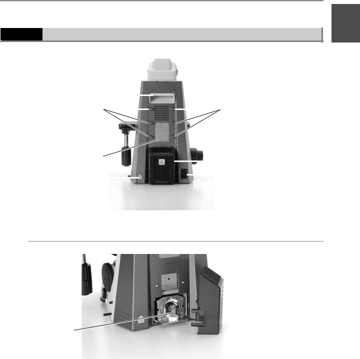
1.2.4Rear view (55i)
|
|
Handle |
|
|
|
|
|
|
|
|
|
|
|
|
|
|
|
|
|
|
|
|
|
|
|
|
|
|
|
|
|||
|
Wire guides |
|
|
|
|
|
|
|
|
|
Wire guides |
|||||
|
|
|
|
|
|
|
|
|
|
|||||||
|
|
Tool |
|
|
|
|
|
|
|
|
|
|
Wiring cover |
|||
|
|
|
|
|
|
|
|
|
|
|
|
|||||
|
|
|
|
|
|
|
|
|
|
|
|
|
|
|
||
|
|
|
|
|
|
|
|
|
|
|
|
|
|
|||
|
55i with wiring cover open |
|
|
|
|
|
|
|
|
|
|
|
||||
|
|
|
|
|
|
|
|
|
|
|
|
|
|
|
|
|
|
|
|
|
|
|
|
|
|
|
|
|
|
|
|
||
|
Connector J4 |
|
|
|
|
|
|
|
|
|
Connector J2 |
|||||
(for cytodiagnostic |
|
|
|
|
|
|
|
|
|
|
|
|
|
|||
|
|
|
|
|
|
|
|
|
|
|
(for cytodiagnostic unit |
|||||
|
unit signal cable) |
|
|
|
|
|
|
|
|
|
|
|
|
|
||
|
|
|
|
|
|
|
|
|
|
|
|
power supply cable) |
||||
|
|
|
|
|
|
|
|
|
|
|
|
|
|
|
||
|
|
|
|
|
|
|
|
|
|
|
|
|
|
|
||
|
Connector J3 |
|
|
|
|
|
|
|
|
|
|
|
||||
|
|
|
|
|
|
|
|
|
|
Connector J1 |
|
|||||
(for cytodiagnostic |
|
|
|
|
|
|
|
|
|
|
||||||
|
|
|
|
|
|
|
|
|
(for AC adapter) |
|
||||||
|
unit hand switch) |
|
|
|
|
|
|
|
|
|
|
|||||
|
|
|
|
|
|
|
|
|
|
|
|
|||||
|
|
|
|
|
|
|
|
|
|
|
|
|
|
|||
|
55i with cables connected |
Battery |
|
holder |
||||||||||||
|
|
|||||||||||||||
|
|
|
|
|
|
|
|
|
|
|
|
|||||
|
|
|
|
|
|
|
|
|
|
|
|
|
|
|
|
|
Cytodiagnostic unit |
|
|
|
|
Cytodiagnostic unit |
|
signal cable |
|
|
|
|
power supply cable |
|
|
|
|
|
|||
|
|
|
|
|
|
AC adapter cable |
Cable for |
|
|
||||
|
|
|
|
|
||
|
|
|||||
|
|
|
|
|
|
|
cytodiagnostic unit |
|
|
|
|
|
|
hand switch |
|
|
|
|
|
|
|
|
|
|
|
|
|
18
Chapter 1 Part Names
1.2Names of Parts Used to Make Adjustments
1
1.2.5Ergonomic binocular tube with camera attached
Camera cable connector
Camera head
C mount
 Camera fine focus adjustment ring
Camera centering screws
Attachment guide fixing screw
19
Chapter 1 Part Names
1.2Names of Parts Used to Make Adjustments
1.2.6With cytodiagnostic unit attached
Magnification indicator 
Object marker knob
Hand switch
Side and rear views of cytodiagnostic unit
50i: AC adapter cable (thick)
55i: J-CY/PS Power supply cable (thick)
 Cytodiagnostic unit power switch
50i: Hand switch cable (thin)
55i: J-CY/SG Signal cable (thin)
Ink cartridge
20

Chapter 1 Part Names
1.2Names of Parts Used to Make Adjustments
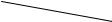
1
1.2.7With Epi-Fl attachment mounted
Optical path switching lever
Mercury lamphouse
Filter cube motion restricting lever
Shutter
Light shielding plate |
Field diaphragm lever |
|
Filter cube switching knob
(Mercury lamp requires a separate mercury lamp power supply.)
|
|
|
|
|
|
Filter cube replacement cover |
|
ND filters |
|||
|
|
|
|
21
2 Microscopy
2.1Bright-Field Microscopy
The ECLIPSE 55i with the low magnification objective may result in uneven illumination in the field of view.
(If the cytodiagnostic unit is attached, refer to the directions in the following section entitled “2.2 Microscopy with Cytodiagnostic Unit Attached.”)
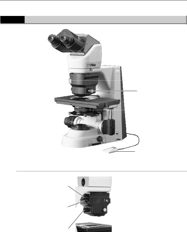
1 Turn on power.
P.35
2 Raise the condenser to the uppermost position.
Press the power switch to the “|” position.
Raise the condenser using the condenser focus knob.
3 Fully open the field diaphragm and aperture diaphragm.
Fully open the aperture diaphragm using the aperture diaphragm knob.
Fully open the field diaphragm using the field diaphragm knob.
22

Chapter 2 Microscopy
2.1 Bright-Field Microscopy
4 Set the 10x objective into the optical path.
2
Select the 10x objective.
5 Set a specimen and move the portion to be viewed into the optical path.
P.42
Set a specimen and secure in place using the specimen holder.
Move the portion to be viewed into the optical path using the XY stage knobs.
6 Focus on the specimen.
P.40
Focus on the specimen using the coarse and fine focus knobs.
23

Chapter 2 Microscopy
2.1 Bright-Field Microscopy
7 Adjust the diopter and the interpupillary distance.
P.43
P.44
8 Focus and center the condenser.
P.45
Focus the condenser |
Center the condenser |
using the condenser |
using the condenser |
focus knob. |
centering screws. |
9 Switch to the desired objective and view the specimen.
Adjust the field diaphragm and aperture diaphragm each time you change objectives.
P.46
P.47
Select the desired objective.
Aperture diaphragm knob
Field diaphragm knob
24
 Loading...