


VBA26001-R.3786.A
VBA26001
REPAIR MANUAL
Copyright 2009byNikonCorporation.
AllRightsReserved.
Printed in Japan August 2009
User ID:INC
VBA26001-R.3786.A
Points to notice for Disassembly and Assembly
 WARNING
Take extra care not to get an electric shock when detaching
covers.
 After removing covers, be sure to discharge the main
condenser according to the instructions of repair manuals.
Caution:
In disassembly/(re)assembly, be sure to use conductive mat (J5033) and wrist strap (J5033-5), in order to protect electric parts from static electricity.
Before disassembling, be sure to remove batteries or AC power cord.
In disassembling, be sure to memorize the processing state of wires and FPC, screws to be fixed and their types, etc.
The low-pass filter of the image PCB/base plate is easily damaged. Handle it very carefully.
is indicated in this manual when NK screw is used. Usually the same "NK" screw can be used
approx. up to three times. (NK screw = Loose-proofing screw to which the adhesive is already applied and firmly fixed when screwed in.)
Points to notice for Lead-free solder products
Lead-free solder is used for this product.
For soldering work, the special solder and soldering iron are required.
Do NOT mix up lead-free solder with traditional solder.
Use the special soldering iron respectively for lead-free solder and lead solder. They cannot be used in common.
Caution:
When "Separation of Front body from Rear body", "Disassembly of CCD/FPC unit" and "Disassembly of Bayonet" are performed, be sure to carry out "RESET AF-DEFOCUS COMPENSATION" of the D300s adjustment software after assembly.
- D300S -
User ID:INC
VBA26001-R.3786.A
Di emy
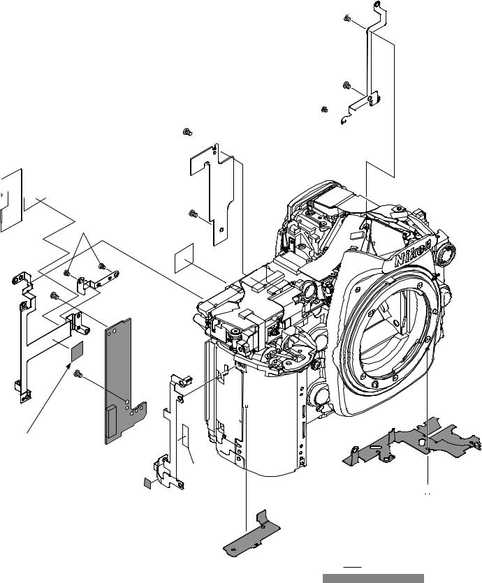
Extern re nd Im ge-re ted PCB/ e p te
External rubber |
Different part from D300. |
|
#B447 |
||
Remove the external rubbers |
||
|
||
(#B60, #B61, #B63, and #B447). |
|
#B61
 #1647
#1647
#B63
#B60
C uti n: T ke ut the cre 647 fir t, nd then rem ve the grip ru er B6
IF lid The procedure is the same as that of D300. Refer to Page D2 of D300 repair manual.
Bottom cover / Battery lid unit |
The procedure is the same as that of D300. Refer to Page D3 of |
||
|
|
D300 repair manual. |
|
Rear cover unit |
The procedure is the same as that of D300. |
Refer to Page D4 of D300 repair manual. |
|
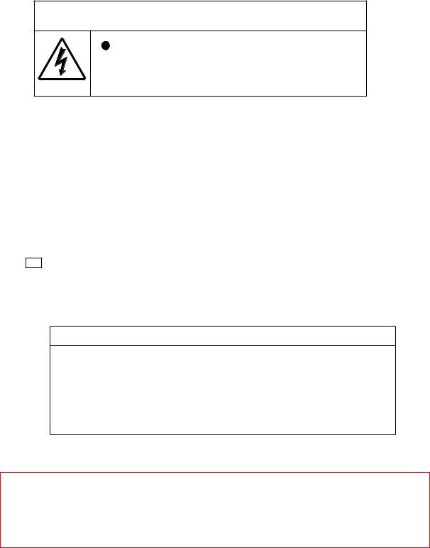
CF cover, sponge, other small parts |
|
|
|
Take out the two screws (#1518). |
|
||
|
|
B441 |
|
Different part from D300. |
|
|
|
|
|
#445 |
|
|
|
|
#443 |
B441 |
|
|
|
|
#1518 × 2 |
|
|
|
|
- D1 D300S - |
|
User ID:INC
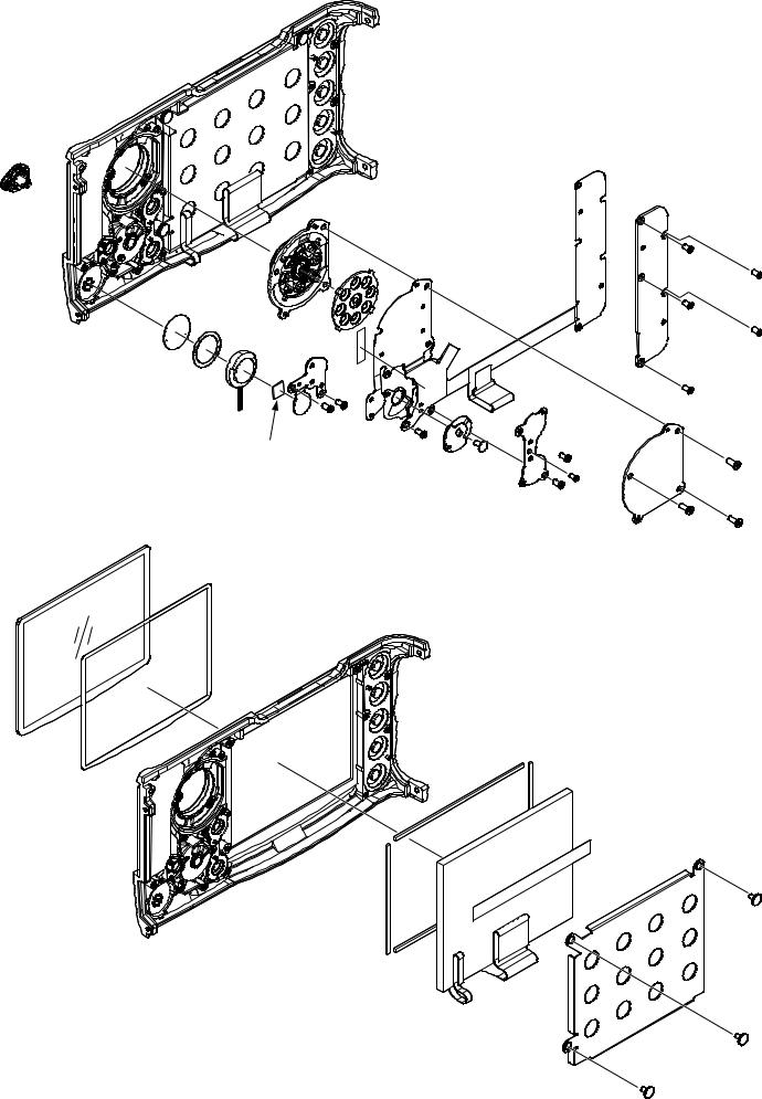
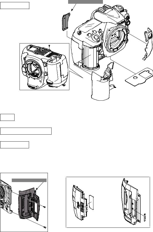
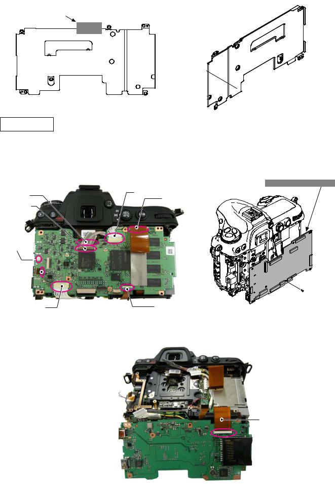
Rear SW FPC, Retainer plate, and other small parts
#476
#B467 |
|
|
|
#470 |
|
#463 |
#772 |
|
#495 |
||
#464 |
||
#1052 |
#1541 × 2 |
|
|
||
#462 |
#1541 |
TFT monitor and other small parts
#431
#433
#435 × 2
- D2 D300S -
VBA26001-R.3786.A
#456
#1560 × 5
#1020
#1630
#B478
 #1541 × 2
#458 #1534
#422 |
#1589 × 3 |
|
#434 × 2
#1057
#436
#432
#1626 × 3
User ID:INC
Selector button, Sponge, and other small parts
#986
#468 |
#987 |
|
#440
 #484
#484
#426 #475
VBA26001-R.3786.A
#985
 #962
#962
#455
#961
#924
#B469  #1517 × 3
#485
#457
I/F cover
Take out the two screws (#1510) and the screw (#1528)Remove the I/F cover (#28).
Remove the conduct plate (#695).
#695
- D3 D300S -
Different part from D300.
#28
 #1528
#1528
#1510×2
User ID:INC
VBA26001-R.3786.A
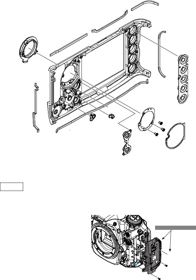
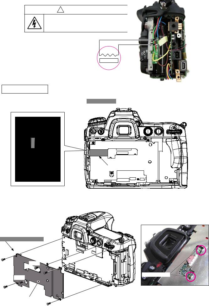
Discharge of Main condenser
! WARNING
 There are high voltege parts inside. Be careful of this electric shock, when you remove the cover.
 You must discharge the main condenser according to the instruction of this repair manual after you remove the cover.
2KΩ/5W
DG PCB shield plate |
Peel off the gasket (#693 and #694). Added part to D300s.
#693
#694
Take out the four screws (#1546) and two screws (#1515).
Remove the two soldering bridges that joint DG-PCB and DG-PCB shield plate (#B683RP).Remove the DG-PCB shield plate (#B683RP).
Different part from D300.
#1515
#1515 |
Soldering bridge |
|
|
DG-PCB shield plate unit |
|
(#B683RP) |
#1546 × 4 |
|
|
|
- D4 D300S - |
User ID:INC
VBA26001-R.3786.A
Peel off the tape TA-0020 (10 × 20).
Peel off the drip proof sponge (#773).
TA-0020(10 × 20) |
#B683RP |
#773 
#B683RP
DG Plate unit
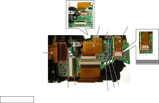
Remove the harnesses (#1075, #1074, and #1073) from each connector.
Disconnect the FPC (#1027,#1040,#1039,#1016) and the microphone wire connector from each connector.
Take out the screw (#1546) and remove the DG plate unit (#B1017RP).
Different part from D300.
#1016 |
#1074 |
#1039 |
#1075 |
|
|
|
|
microphone wire connector 
#1040
|
|
#1546 |
#1073 |
#1027 |
#B1017RP |
|
Disconnect the FPC (#1038) from the connector.
#1038
- D5 D300S -
User ID:INC
VBA26001-R.3786.A
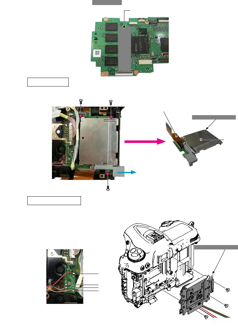
Peel off the shield plate (#692). Added part to D300s.
#692
CF base plate unit
Take out the three screws (#1543) and remove the CF base plate (#1018).
#1038
Different part from D300.
#1018
Pull out
#1543 × 3
Image sensor holder unit
Unsolder the DR base plate (#1014) at four places.Take out the three screws (#1639) and remove the
image sensor holder unit (#B10521).
 DR base plate

 Red
Red 


Black
Gray
Orange


 Different part from D300.


 #1014
#1014


 #B10521
#1639 × 3
- D6 D300S -
User ID:INC
Top cover unit |
VBA26001-R.3786.A |
|
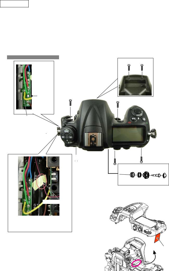
Removal of Top cover
Remove the dioptor-adjustment knob cover plate (#850), and take out the screw (#1622).Remove the dioptor-adjustment knob (#852), drip-proof sponge (#857) and drip-proof collar (#851).
Raise the built-in SB (flash unit), and take out the two screws (#1548), two screws (#1547), three screws (#1555) and two screws (#1511).
Remove the five solders of the DI base plate (#1029).
Different wiring position from D300.
#1548 × 2

 Blue
Blue

 Black
Black

 Red
Red
Green |
#1511 × 2 |

 Brown
Brown
DI base plate
(#1029)

 #1555
#1555
#1555 

 #1547 × 2
TA-0005(15 × 6)
|
#1555 |
|
#851 |
#852 |
#850 |
#857 |
#1622 |
|
Dioptor adjustment knob |
|
|
Peel off the tape (TA-0005), and remove the wires (red/black) of the microphone.
Lift the top cover slowly so as not to cut the FPC, and disconnect the FPC
from the connector.
FPC
- D7 D300S -
User ID:INC
VBA26001-R.3786.A
DR base plate and other small parts


 #690 #1537 × 2

#1502 


#1541 × 2 
 #1014
#1014
#B685RP


 #564
#564
#1502 × 2 
 TA-0005(26 × 6)
#1541 |
#688 |
#1048
#691 #1541
 #B687
#B687
TA-0020(15.4 × 9.7)
#769
#449 #439  #1537
#1537
#1027

 :Parts
Different parts from D300.
- D8 D300S -
User ID:INC
Command dial, Shoe base and other small parts |
|
|
|
|
VBA26001-R.3786.A |
||
|
|
#318 |
|
|
|
||
Shoe base |
|
|
|
|
#316 |
|
|
|
|
|
|
|
|
|
|
Take out the four screws (#321). |
|
|
|
|
|
#948 × 2 |
|
Remove the four solders from the |
|
|
|
|
|
||
|
|
|
|
|
|
|
|
shoe base. |
Solder |
|
|
#B317 |
|
|
|
|
|
|
|
|
|
||
#701 |
|
|
|
|
|
|
|
|
|
|
|
|
|
|
#757 |
|
|
|
|
|
|
|
#758 |
#702 |
|
|
|
|
|
|
|
#754 × 2 |
|
|
|
|
#B1003 |
|
|
|
|
|
|
|
|
|
|
|
|
|
|
|
|
|
#920 |
#708 |
|
|
|
|
|
|
|
|
|
|
|
|
|
|
#972 |
#B726 |
|
|
|
|
#321 × 4 |
|
#996 |
Solder |
|
|
#324 |
|
|
#1541 |
|
#1571 |
× 2 |
|
#517 |
#520 |
|||
|
|
||||||
|
#323 |
|
|
|
|
||
|
|
|
|
|
|
|
|
|
|
|
#1033 |
|
#1541 |
|
#1051 |
|
|
|
|
#1565 |
|
||
|
|
|
|
|
|
||
|
|
|
|
|
#1013 |
||
|
|
|
|
#B725 |
|
||
|
|
|
|
|
|
|
|
#B735 |
|
|
|
#1544 × 2 |
#1541 |
#1535 |
|
|
|
|
|
|
|
:Parts |
|
#1605 |
|
Solder |
Soldering bridge |
Different part from D300. |
|||
|
|
|
|||||
Command dial/ Release-SW
Unsolder the release-SW (#B735), command dial (#B726)(#B725), and remove the soldering bridges, then remove the FPC (#B1033).
Take out the two screws (#1571) and two screws (#1544), and remove the command dial.
Take out the screw (#1605) and remove the release-SW.
SB-PCB
Disconnect the FPC from the connector.
Unsolder the six SB wires of SB flash unit and the wire of the synchro-terminal.
Take out the screws ( #1535 and #1541), and remove the SB-PCB.
#958
SB-PCB soldering position |
Black |
|
|
|
Blue |
DI base plate |
|
Blue |
Red |
||
|
|||
Green |
|
||
Green |
|
||
|
|
||
Orange |
|
|
|
Gray |
|
|
|
FPC |
Green Sync. terminal |
||
|
|
||
Brown |
|
|
|
Black |
|
|
|
SB flash unit |
|
|
|
- D9 D300S - |
Different wiring position from D300. |
||
User ID:INC
|
Outside LCD, Release SW and other small parts |
|
VBA26001-R.3786.A |
|||||||
|
|
|
|
|
||||||
|
|
|
|
The procedure is the same as that of D300. |
Refer to Page D11 of D300 repair manual. |
|||||
|
|
|
|
|
|
|
||||
|
Outside LCDFPC |
The procedure is the same as that of D300. |
Refer to Page D11 of D300 repair manual. |
|||||||
|
|
|
|
|
|
|
|
|
|
|
|
Metering mode dial, Power dial and other small parts |
|
|
|
|
|||||
|
|
|
|
The procedure is the same as that of D300. |
Refer to Page D11 of D300 repair manual. |
|||||
|
SB case, Synchro-terminal and other small parts |
|
|
|
|
|||||
|
|
|
|
The procedure is the same as that of D300. |
Refer to Page D12 of D300 repair manual. |
|||||
|
Mode dial, Eyelet and other small parts |
|
|
|
|
|||||
|
|
|
|
The procedure is the same as that of D300. |
Refer to Page D13 of D300 repair manual. |
|||||
|
|
|
|
|
|
|
|
|
||
|
Mode dial / Trefoil button |
|
|
|
|
|
||||
|
|
|
|
|
|
|
||||
|
|
|
|
The procedure is the same as that of D300. |
Refer to Page D13 of D300 repair manual. |
|||||
|
|
|
|
|
|
|||||
|
Synchro-terminal |
|
The procedure is the same as that of D300. |
Refer to Page D13 of D300 repair manual. |
||||||
|
|
|
|
|
|
|||||
|
|
|
|
|
||||||
|
Mode dial FPC |
|
The procedure is the same as that of D300. |
Refer to Page D13 of D300 repair manual. |
||||||
|
|
|
The other working process than attaching the tape (#933) is the same as D300. |
|||||||
|
|
|
||||||||
|
Main PCB unit |
|
|
|||||||
|
|
|
|
Refer to Page D14 of D300 repair manual. |
|
|
|
|
||
|
|
|
|
|
|
|
|
|||
Peel off the tape (#933). |
|
|
|
|
||||||
|
|
|
|
|
|
|
Shutter-FPC |
|
|
|
|
|
|
|
|
|
|
|
|
|
|
|
|
|
|
#1009 |
#1030 |
|
|
|||
|
|
|
|
|
|
|
Main-PCB (#B1001) |
|
|
|
|
|
|
|
|
|
|
|
|
|
|
|
|
|
|
|
|
|
|
|
|
|
#1005
#933
Added part to D300s.
|
BLACK:AF-assit |
|
|
|
|
|
BLACK:AF-assit illuminator lamp unit |
|
|
Yellow:Detection |
-SW |
||
illuminator lamp |
|
BLUE: |
Power contact |
|
||
|
||||||
VIOLET: Power contact |
||||||
|
unit |
|||||
Eyepiece mold unit The procedure is the same as that of D300. Refer to Page D14 of D300 repair manual.
2 Sep r ti n f Fr nt dy fr m Re r dy
The procedure is the same as that of D300. Refer to Page D15 of D300 repair manual.
The procedure is the same as that of D300. Refer to Page
D15-D21 of D300 repair manual.
- D10 D300S -
User ID:INC

4 Re r dy |
VBA26001-R.3786.A |
Charge-base plate, I/F base plate, Main condenser and other small parts |
|
#1573 × 3 |
#1572 |
|
|
|
|
|
#1638 |
|
|
#933 |
|
|
|
|
|
|
#B326 |
|
|
#825 |
#614 |
|
|
|
#B602 |
|
|
|
|
|
|
|
#B1067 |
|
|
|
|
|
|
|
#606 × 2 |
#611 |
|
#930 |
|
|
|
#1029 |
#1564 |
|
|
|
|
|
|
|
|
|
#1101 |
|
|
|
|
#1102 |
#B1067
#1029
#1564
I/F base plate (#B1019) soldering position
|
|
|
|
#710 |
|
|
|
|
|
|
|
|
#399 |
|
Yellow |
|
|
|
|
#955 |
|
|
|
|
|
|
|
|
|
|
|
|
|
|
|
|
|
#1012 |
#1509 × 2 |
|
|
Brown |
|
Battery |
Filter board unit |
|
#1543 |
× 2 |
DI base plate |
contact |
|||
|
|
|
||||||
|
#1012 |
812 |
#B1019 |
|
|
|
|
|
|
DCDCSZ |
|
|
|
|
Black |
||
|
|
|
|
|
|
|
|
|
|
base plate |
|
|
|
|
|
|
Red |
|
Black |
|
|
|
|
|
|
|
|
|
|
|
|
|
|
DCDCAK |
|
Black |
Blue |
|
|
|
|
|
|
|
DCDCAK |
|
|
|
|
|
|
base plate |
|
Yellow |
|
|
|
|
|
|
|
|
base plate |
|
|
|
|
|
|
Blue |
|
|
|
|
|
|
|
|
||
|
|
#1549 × 3 |
|
#396 |
|
|
|
Yellow |
|
|
|
|
|
|
|
Red |
|
|
|
|
#1040 |
|
|
|
|
Black |
|
|
|
|
|
Different wiring position from D300. |
|||
|
|
|
#397 |
:Parts |
|
|||
|
|
|
|
|
|
|
||
|
|
|
Different parts from D300. |
Green |
DCDCSZ base plate |
|||
|
|
|
Black |
|||||
|
#1047 |
|
|
|
Filter board unit |
|||
|
|
|
|
Yellow |
||||
|
#1541 × 2 |
Blue |
|
|
#1541 |
|
||
|
|
|
|
|
|
|||
|
|
|
Yellow |
|
|
|
OP power base unit |
|
|
|
|
Red |
|
|
|
Gray |
|
|
|
|
Black |
|
|
|
|
|
|
|
I/F base plate |
|
|
|
Orange |
|
|
|
|
DCDCAK base plate |
|
|
|
Brown |
|
|
|
|
|
|
|
Orange |
|
||
|
|
(#1047) |
#1541 |
|
|
|
Black |
Charge motor |
|
|
|
|
|
|
Different wiring position from D300. |
|||
Shutter unit |
||||
The procedure is the same as that of D300. Refer to Page D23 of D300 repair manual. |
||||
Rear body accessories The procedure is the same as that of D300. Refer to Page D23 of D300 repair manual.
- D11 D300S -
User ID:INC
A em y / Adju tment
Re r dy |
|
VBA26001-R.3786.A |
|
|
|
||
|
The procedure is the same as that of D300. |
Refer to Page A1 of D300 repair manual. |
|
Rear body accessories |
|||
|
|
|
|
|
The procedure is the same as that of D300. Refer to Page A2 of D300 repair manual. |
||
Shutter unit |
|||
|
|
The procedure is the same as that of D300. |
Refer to Page A2 of D300 repair manual. |
|
|||
Charge base plate unit |
|||
|
|
|
|
Charge base plate, I/F base plate, Main condenser The other working process than described here is the same as D300.
Refer to Page A3 of D300 repair manual.
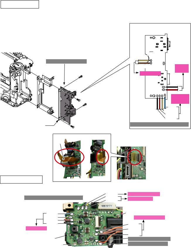
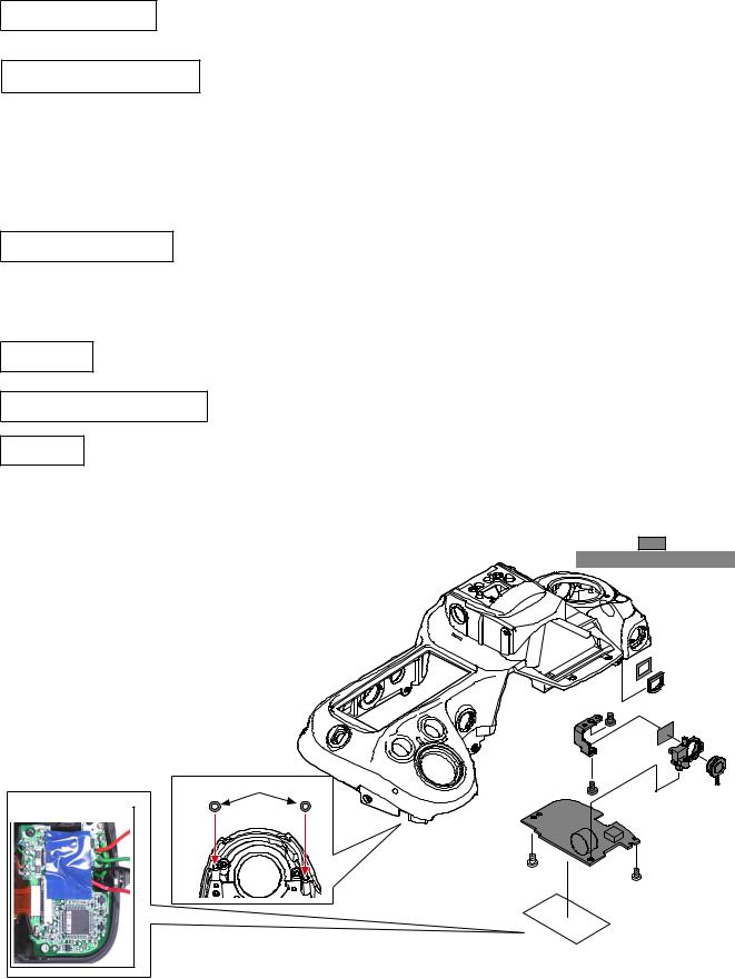
I/F base plate unit
Mount the I/F base-plate fixing plate (#396) on the I/F base plate (#B1019). Then tighten the two screws (#1509).
Connect the FPC (#1040) to the connector of the I/F base plate.
Attach the GND plate (#397) by fitting it with the four bosses which are for positioning the body.
Mount the I/F base plate (#B1019) by fitting in the body's groove and with two
positioning bosses. Then, tighten the two screws (#1543).
Different part from D300.
#397 |
#1509 × 2 |
I/F base plate(#B1019) soldering position
Yellow 
Brown |
Battery |
DI-base plate |
contact |
|
|
|
Black |
|
#B1019 |
#396 |
#1543 × 2 |
|
|
|
#1040 |
DCDCAK base plate (#1047) #1541
- A1 D300S -
User ID:INC
VBA26001-R.3786.A
2 Fr nt dy The assembly procedure is the same as that of D300. Refer to Page A4-A11 of D300 repair manual.
|
|
|
The procedure is the same as that of D300. |
Height adjustment ofAF coupling shaft |
|
||
|
|
|
Refer to Page A7 of D300 repair manual. |
|
|
|
|
|
|
The procedure is the same as that of D300. |
|
Height adjustment ofAperture lever |
|
||
|
|
Refer to Page A7 of D300 repair manual. |
|
|
|
|
|
Angle adjustment of Main mirror and sub-mirror
Refer to separate "Instruction manual for Mirror-Angle Reference Tool" for how to use the main/sub-mirror angle inspection equipment (J19132).
< Standard value > |
|
|
|
|
|
|
Main mirror |
Sub-mirror |
Left-right |
0 ±10’ |
- |
deviation |
|
|
Up-down |
0±4’ |
-15±15’ |
deviation |
|
|
Distortion |
6’or less |
6’or less |
Rough indication: Height of measurement-use mirror of D300S
M unting f Fr nt dy n Re r dy
Mounting of Front body on Rear body |
The procedure is the same as that of D300. Refer to Page A13 |
|
of D300 repair manual. |
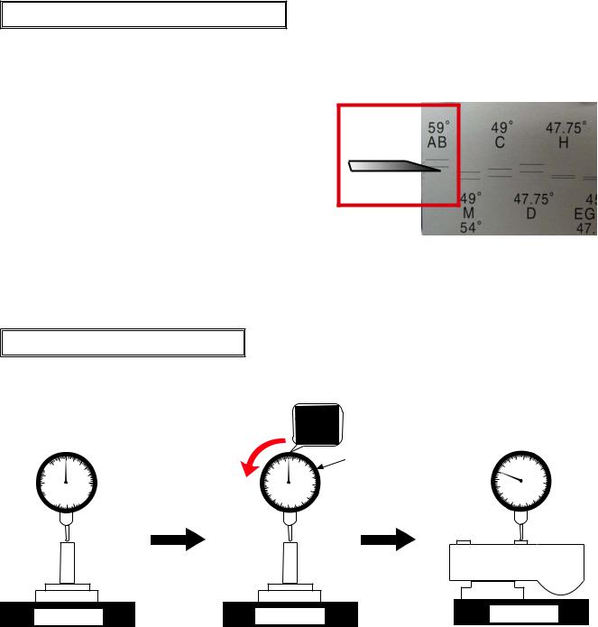
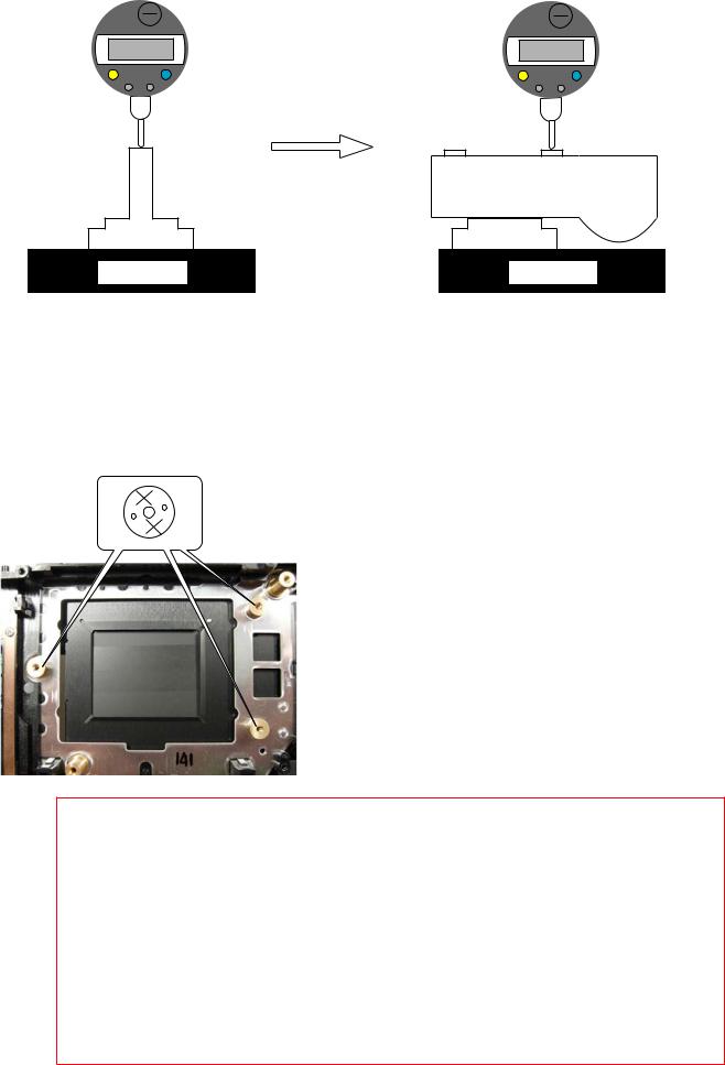
Inspection and Adjustment of Body back
"0" positioning of the dial gauge

 10 0 10
20 |
20 |
 30 30
30 30


 40 50 40


 J18001-1
Surface plate
Turn counterclockwise to 18 (0.18mm) position
 10
10  20
20
Index circle
|
|
|
30 |
10 |
|
|
40 |
|
|
50 |
|
|
20 |
|
|
|
30 |
40 |
|
|
|
||
|
|
|
Surface plate
Standard: 0±0.015 mm Parallelism: 0.015 mm or less
10 |
|
20 |
30 |
|
|
||
0 |
|
|
40 |
10 |
|
|
|
|
|
50 |
|
20 |
|
|
|
30 |
|
40 |
|
|
|
||
|
|
|
Surface plate
(1)Mount the tool (J18001-1) on the surface plate as above, then set the dial gauge to "0".
(2)From "0" position of (1), turn the index circle in the direction of the arrow so that the needle is on 18 (0.18mm) position.
(3)Measure the body back based on "0" position of the index circle.
If the value is "0±0.015 mm / Parallelism: 0.015mm or less", it is within standard.
- A2 D300S -
User ID:INC
VBA26001-R.3786.A
"0" positioning of the digital gauge
|
0.00mm |
ZERO/ABS |
ON/OFF |
PRESET |
TOL. |
J18001-1
Surface plate
|
1.82mm |
ZERO/ABS |
ON/OFF |
PRESET |
TOL. |
1.82-1.82 0 So this is within standard.
Surface plate
(1)Mount the tool (J18001-1) on the surface plate as above, then turn the digital gauge ON and press [ZERO/ ABS] button so that the value becomes "0".
(2)Measure the body back based on "0" position
(3)Subtract "1.82mm" from the measured value. If the value is "0±0.015 mm / Parallelism: 0.015mm or less",
it is within standard.
" 2mm" i difference, re u ting fr m u tr cting [the height 46 67mm f the dy ck t J - ] fr m [D t nd rd v ue 4 49mm ]
Measure six places from the bayonet face to the image sensor
attaching face.
× mark: to be measured
Standard: 48.49±0.015mm / Parallelism: 0.015mm or less
In case the result is out of standard, make an adjustment by putting the washers between the front body and the rear body.
Note: For some bodies, the washer(s) is/are already put on the attaching face of the image sensor
. There are indications at the following two positions.
1. Indication: on the camera body side
Purpose To adjust the height of the camera body2. Indication: on the image sensor unit side
Purpose To adjust the height of the image sensor
Therefore, in case of the above 1., when the camera body is disassembled or the image sensor unit is replaced, put the washer at the original position. In case of the above 2., when the image sensor unit is replaced, remove the washer.
- A3 D300S -
User ID:INC
VBA26001-R.3786.A
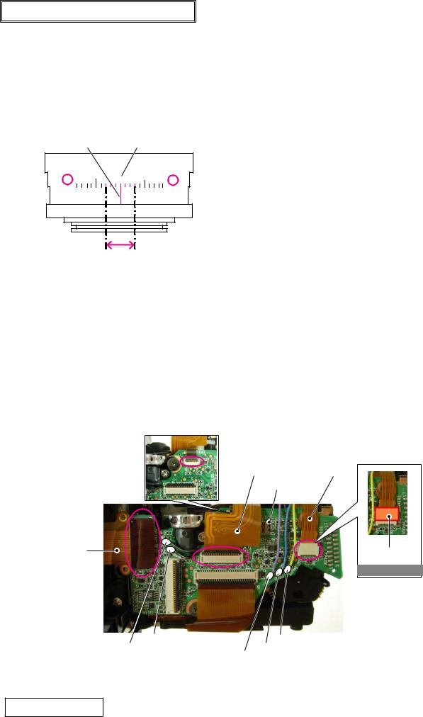
∞ Infinity focus inspection & adjustment
Replace the finder screen with the infinity focus check screen (J18394), and use the reference lens (J18010) and read the value. In case it is out of standard, increase or decrease washers (#836A, #836B, #836C or #836D) for adjustments. * Supply the power (Battery or EH-5) for checking.
Caution: When [J18394] is put in to replace the finder screen, put it with the silver spacers upward, which are
J18010 attached on both sides.
Reference line |
"0" position of tool lens |
|

±3 scales
Standard:±0.03mm (1 scale =0.01mm
#836A |
1K608-832 |
Screen washer A 0.10mm |
#836B |
1K608-833 |
Screen washer B 0.20 mm |
#836C |
1K602-840 |
Screen washer C 0.15mm |
#836D |
1K608-977 |
Screen washer D 0.05mm |
|
The procedure is the same as that of D300. |
||
Parallax inspection and adjustment |
|||
|
|
Refer to Page A55 of D300 repair manual. |
|
|
|
|
|
|
The other working process than attaching the tape (#933) is the same as D300. |
||
Main PCB unit |
|||
Refer to Page A15 of D300 repair manual. |
|||
|
|||
Attach the tape (#933).
 Shutter FPC
#1009
Main PCB (#B1001)
#B1005 |
#933 |
|
Added part to D300s.
|
|
|
|
|
|
BLACK:AF-assist lamp unit |
Yellow:Detection-SW |
||||
BLUE: |
Power contact |
|
|||
BLACK:AF-assist lamp unit |
|
|
|
|
|
VIOLET: Power contact |
|||||
|
|||||
Eyepiece mold unit The procedure is the same as that of D300. |
Refer to Page A15 of D300 repair manual. |
- A4 D300S -
User ID:INC
T p c ver |
VBA26001-R.3786.A |
|
Eyelet,AF-assist illuminator protector, Function-button external ring The procedure is the same as that of D300. Refer to Page A16 of D300 repair manual.
Mode dial, Trefoil rubber button and other small parts The procedure is the same as that of D300. Refer to Page A17 of D300 repair manual.
Mode dial FPC unit The procedure is the same as that of D300. Refer to Page A17 of D300 repair manual.
Mode dial / Trefoil button The procedure is the same as that of D300. Refer to Page A17 of D300 repair manual.
SB case, Syncrho-terminal and other small parts The procedure is the same as that of D300. Refer to Page A18 of D300 repair manual.
Metering mode dial, Release button and other small parts The procedure is the same as that of D300.
|
Refer to Page A19 of D300 repair manual. |
|
|
|
Outside LCDFPC unit The procedure is the same as that of D300. Refer to Page A20 of D300 repair manual. |
||||
Command dial, Shoe base and other small parts The procedure is the same as that of D300. |
|
|
||
|
Refer to Page A21 of D300 repair manual. |
|
|
|
Shoe base The procedure is the same as that of D300. Refer to Page A21 of D300 repair manual. |
|
|
||
Command dial/Release SW The procedure is the same as that of D300. |
Refer to Page A21 of D300 repair manual. |
|||
SB-PCB |
|
|
|
|
Solder the four wires on the SB-PCB (#1013). |
|
|
|
|
Attach the plate (#517) to the top cover, and tighten the |
|
|
|
|
screw (#1541). |
|
|
:Parts |
|
Mount the SB-PCB on the top cover, and tighten the screws |
Different parts from D300. |
|||
(#1541 and #1535). |
|
|
|
|
Connect the FPC of the mode dial (#1025) |
|
|
|
|
to the connector. |
|
|
|
|
Solder the six SB wires and the synchro-terminal wire. |
#757 |
|
||
Attach the two washeres (#754). |
|
|
#758 |
|
|
|
|
|
|
|
|
#1541 |
#996 |
|
|
|
#517 |
||
|
|
|
#520 |
|
[#958] |
#754 × 2 |
#1541 |
|
#1051 |
|
|
|
||
attachment position |
|
#1013 |
|
|
|
|
|
||
|
|
#1541 |
|
|
|
|
#1535 |
|
|
|
|
#958 |
|
|
|
- A5 D300S - |
|
|
|
User ID:INC
SB-PCB (#1013) soldering position
Blue 
Green 


Orange

Gray


FPC
Brown 
Black 


 SB flash section
VBA26001-R.3786.A
Black
Blue DI base plate Red
Green
Green Synchro-terminal
Different wiring position from D300.
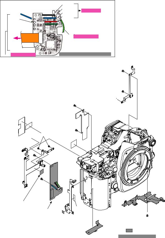
DR base plate and other small parts |
|
#690 |
|
#1537 |
× 2 |
||
|
#1502 
|
#1541 × 2 |
#B685RP |
|
#564 |
#1014 |
 #1502 × 2TA-0005(26 × 6)
#1541 |
#688 |
#691
#1541
TA-0020(15.4 × 9.7)
Blue: Filter board unit
Black: Filter board unit
Green: DC/DC AK PCB unit
#1048
#B687
|
#769 |
|
#449 |
#439 |
#1537 |
|
|
|
|
#1027 |
:Parts |
Different parts from D300.
|
The procedure is the same as that of D300. |
Inspection and adjustment of AE CCD positioning |
|
|
Refer to Page A27 of D300 repair manual. |
- A6 D300S - |
|
User ID:INC
 Loading...