


 Loading...

Start Here
Congratulations on your purchase of the NETGEAR™ Model EN516 or Model EN524 Ethernet hub. These hubs deliver standards-based, plug-and-play networking solutions for small businesses, home offices, and low-density workgroups of larger companies.
Features
The Model EN516 and Model EN524 hubs have the following features:
•Sixteen (on the Model EN516 hub) and twenty-four (on the Model EN524 hub) vista 10BASE-T network ports (RJ-45) that provide 10 Mbps networking using simple unshielded twisted pair (UTP) wiring (The vista network ports provide built-in LED indicators for at-a- glance status checks.)
•AUI or coaxial BNC backbone support for connecting to an existing Ethernet segment or external transceiver, or for network expansion by connecting multiple hubs together using twisted pair or coaxial cabling
•Uplink port for connecting to other hubs using simple straight-through cables
•Built-in 100 to 240 V AC switching power supply, eliminating the need for bulky wall transformers
•Clear front-panel light-emitting diode (LED) indicators, providing the individual ports and overall hub status
•Plug-and-play installation with no software to configure
•Complete hub functions including packet retiming, collision detection, preamble regeneration, and fragment extension
•Automatic partitioning and reconnection of a port that has excessive collisions or is jabbering
•Automatic polarity detection for recognizing and correcting incorrect polarity on the receive pair
•Compact design, enabling easy tabletop or rack-mounting installation
•Limited five-year warranty on the unit and one-year warranty on the power supply
Model EN516/EN524 Ethernet Hub Installation Guide
Package Contents
Model EN516 hub |
Model EN524 hub |
|
or |
|
|
|
MODELEN516 |
16PORT |
|
|
24 PORT |
Ethernet Hub |
1 |
8 |
Ethernet Hub |
Link/Rx |
Partition |
Link/Rx |
Partition |
|
|
|
Normal/Uplink |
9 |
|
|
16 |
1 |
|
|
|
|
|
|
|
5 |
|
|
|
|
|
|
|
|
|
MODELEN524 |
||
|
|
|
|
|
|
|
|
|
|
|
|
|
|
|
|
12 |
|
|
||
|
Link/Rx Partition |
|
Link/Rx Partition |
Link/Rx Partition |
||||||||||||||||
13 |
|
|
|
|
|
|
|
17 |
|
|
|
|
|
|
|
|
|
Normal/Uplink |
||
|
|
|
|
|
|
|
|
|
|
|
|
|
|
|
|
|
|
|
||
|
|
|
|
|
|
|
|
|
|
|
|
|
|
|
|
24 |
|
|
||
|
|
|
|
|
|
|
|
|
|
|
||||||||||
|
|
|
|
|
|
|
|
|
|
|
|
|
|
|
|
|
|
|
|
|
Rubber |
BNC T-connector |
footpads |
BNC 50 Ω |
|
|
Rack mount kit |
terminator |
|
|
|
Power |
|
cord |
Installation guide,
Warranty & Owner
Registration Card
8668FA
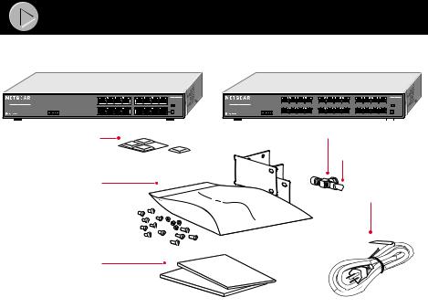
Verify that your package contains the following:
•Model EN516 hub or Model EN524 hub
•Rack mount kit that includes eight small screws, four large screws, four spacers, and two rack mount brackets
•Four rubber footpads
•BNC T-connector and BNC 50 Ω terminator
•Installation guide
•Warranty & Owner Registration Card
•Power cord
Model EN516/EN524 Ethernet Hub Installation Guide
Product Illustration
The instructions provided in this guide are for installing and using the Model EN516 hub and the Model EN524 hub.
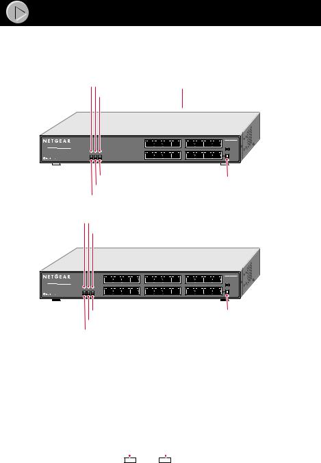
Front Panel of the Model EN516 hub
Power LED BNC Rx LED |
vista 10BASE-T |
||
AUI Rx LED |
network ports |
||
|
|
|
|
|
|
|
|
16PORT
10/100Mbps Ethernet Hub
Power |
BNC |
AUI |
|
Rx |
Rx |
Collision Partition Partition
|
MODELEN516 |
1 |
8 |
Link/Rx Partition |
Link/Rx Partition |
|
Normal/Uplink |
9 |
16 |
|
|
Partition LED (for AUI) |
|
Normal/ |
||
|
|
Partition LED (for BNC) |
Uplink push |
|||
|
|
Collision LED |
|
|
button |
|
Power LED BNC Rx LED |
vista 10BASE-T |
|
||||
|
|
AUI Rx LED |
network ports |
|
||
|
|
|
|
|
|
|
|
|
|
|
|
|
|
24 PORT
10/100Mbps Ethernet Hub
MODELEN524
1 |
5 |
12 |
|
|
Link/Rx |
Partition |
Link/Rx |
Partition |
Link/Rx |
Partition |
Power |
BNC |
AUI |
|
|
|
|
Normal/Uplink |
|
Rx |
Rx |
|
|
|
|
|
Collision Partition Partition |
|
17 |
|
|
24 |
||
|
|
13 |
|
|
|
||
Partition LED (for AUI) |
Normal/ |
Partition LED (for BNC) |
Uplink push |
Collision LED |
button |
Front Panel of the Model EN524 hub
8669FA
Vista 10BASE-T Network Ports with Built-in LEDs
The front panel of the Model EN516 hub has 16 RJ-45 10BASE-T ports, and the Model EN524 hub has 24 RJ-45 10BASE-T ports. Two LEDs—the Link/Rx LED and the Partition LED—are built into each 10BASE-T port on both models.
|
|
Link/Rx |
|
Partition |
|||||
|
|
|
|||||||
|
|
LED |
|
LED |
|||||
|
|
|
|
|
|
|
|
|
|
|
|
|
|
|
|
|
|
|
|
|
|
|
|
|
|
|
|
|
|
|
|
|
|
|
|
|
|
|
|
|
|
|
|
|
|
|
|
|
|
|
|
|
|
|
|
|
|
|
|
|
|
|
|
|
|
|
|
|
|
|
|
|
|
|
|
|
|
|
|
8670EA
Model EN516/EN524 Ethernet Hub Installation Guide
LEDs
The table below describes the activity of the LEDs.
Label |
Color |
Activity |
Description |
|
|
|
|
|
|
Power |
Green |
On |
Power is supplied to the hub. |
|
|
|
|
|
|
Collision |
Amber |
Blinking |
Data collision is occurring on the network. Note that |
|
|
|
|
occasional collisions are normal. |
|
|
|
|
|
|
BNC Rx |
Green |
Blinking |
There is incoming data on the BNC port. |
|
|
|
|
|
|
Partition |
Amber |
On |
The BNC port is partitioned because of excessive |
|
(for BNC) |
|
|
collisions or the BNC port is not connected. |
|
|
|
|
|
|
AUI Rx |
Green |
Blinking |
There is incoming data on the AUI port. |
|
|
|
|
|
|
Partition |
Amber |
On |
The AUI port is partitioned because of excessive |
|
(for AUI) |
|
|
collisions or because the signal quality error (SQE) test |
|
|
|
|
function is not disabled on the transceiver. |
|
|
|
|
|
|
Link/Rx |
Green |
On |
The link between this port and the connected device is |
|
(located on the top left |
|
|
good. |
|
corner of each vista |
|
|
|
|
10BASE-T port) |
|
Blinking |
There is incoming data on the port. |
|
|
|
|
|
|
Partition |
Amber |
On |
The port is partitioned because of excessive collisions. |
|
(located on the top |
|
|
|
|
right corner of each |
|
|
|
|
vista 10BASE-T port) |
|
|
|
|
|
|
|
|
Normal/Uplink Push Button
The Normal/Uplink push button allows you to select Normal (MDI-X) for direct PC connection. The push button also allows you to select Uplink (MDI) wiring for connection to a hub or a switch for port 16 on the Model EN516 hub and for port 24 on the Model EN524 hub. This uplink configuration eliminates the need to use a crossover cable. Ports 1 through 15 on the Model EN516 hub and ports 1 through 23 on the Model EN524 hub are permanently configured for normal wiring for connection to a PC.
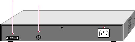
Rear Panel
The rear panel of each hub has two ports: the AUI port and the BNC port. You can use the AUI port with the appropriate transceiver to connect the hub to a backbone network using thin coaxial cable, thick coaxial cable, fiber optic cable, or 10BASE-T wiring. You can use the BNC port to connect to a backbone network or other PCs using thin coaxial cable. The rear panel also includes an AC power receptacle. The hub accepts between 100 and 240 V AC, 50/60 Hz.
AUI port
BNC port |
|
Power receptacle |
|
|
|||
|
|
|
|
|
|
|
|
|
|
|
|
|
|
|
|
BNC
AUI
100-240 VAC 50-60 Hz 0.2A
8143FA
Model EN516/EN524 Ethernet Hub Installation Guide

 Installation Procedures
Prepare the Site
Before you begin installing your hub, prepare the installation site. Make sure your operating environment meets the operating environment requirements of the equipment.
Characteristic |
Requirement |
|
|
Temperature |
Ambient temperature between 0° and 40° C (32° and 104° F). |
|
No nearby heat sources such as direct sunlight, warm air exhausts, or |
|
heaters. |
|
|
Operating humidity |
Maximum relative humidity of 90%, noncondensing. |
|
|
Ventilation |
Minimum 2 inches (5.08 cm) on all sides for cooling. |
|
Adequate airflow in room or wiring closet. |
|
|
Operating conditions |
At least 6 feet (1.83 m) to nearest source of electromagnetic noise (such |
|
as photocopy machine or arc welder). |
|
|
Service access |
Minimum 12 inches (19.68 cm) front and back for service access and |
|
maintenance. |
|
Front and back clearance for cables and wiring hardware such as |
|
punchdown blocks. |
|
|
Power |
Adequate power source within 6 feet (1.83 m). |
|
|
Tabletop requirements |
Flat area approximately 13 inches (33.0 cm) by 8 inches (20.3 cm). |
|
|
Rack requirements |
Standard 19-inch (48.26 cm) EIA equipment rack, with supplied mounting |
|
bracket hardware; 1.0 EIA rack-mount spaces needed for each |
|
NETGEAR hub. |
|
|
Wiring hardware |
Wiring hardware, such as punchdown blocks or patch panels, should be |
|
complete before installing the hub. |
|
|
Model EN516/EN524 Ethernet Hub Installation Guide
Loading...